 BETA
Connect the split supply
Pin 7 uses +15 V and pin 4 uses −15 V. Bypass both rails to their common midpoint.
Build a basic LM741 circuit with labeled pins, component values and connection guidance.
A physical eight-pin IC and a clearly routed feedback loop.
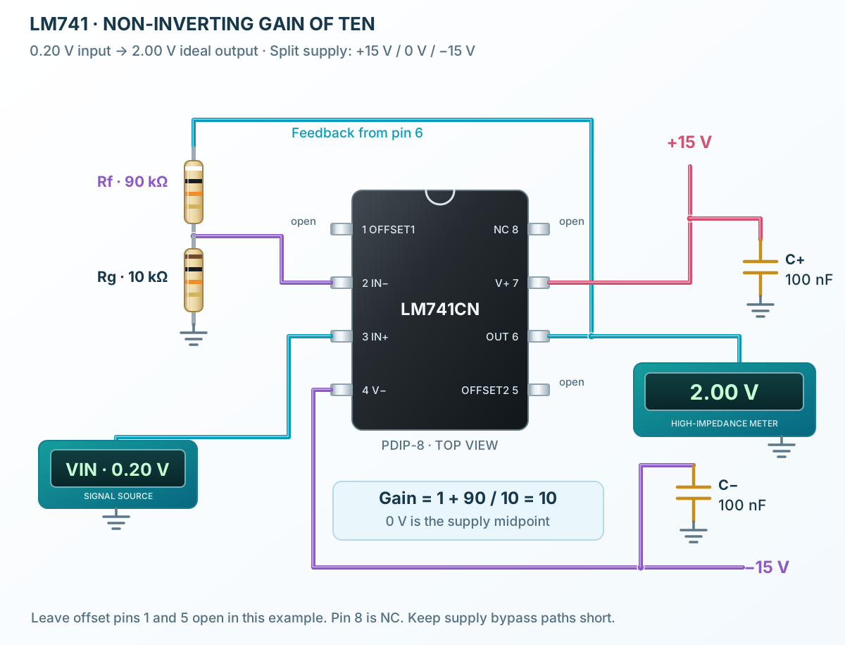
Follow the component values and pin connections
Pin 7 uses +15 V and pin 4 uses −15 V. Bypass both rails to their common midpoint.
90 kΩ connects OUT to IN−, and 10 kΩ connects IN− to the midpoint.
Apply 0.20 V to IN+. A high-impedance meter reads approximately 2.00 V before device errors.