 BETA
Bipolar timer
NE555 Working Principle
Learn how NE555 works with an illustrated explanation and practical readings.
Package view
NE555 at a glance
Follow the labeled connections and functional stages
How it works
3 stages · Explore one step at a time
Power and control
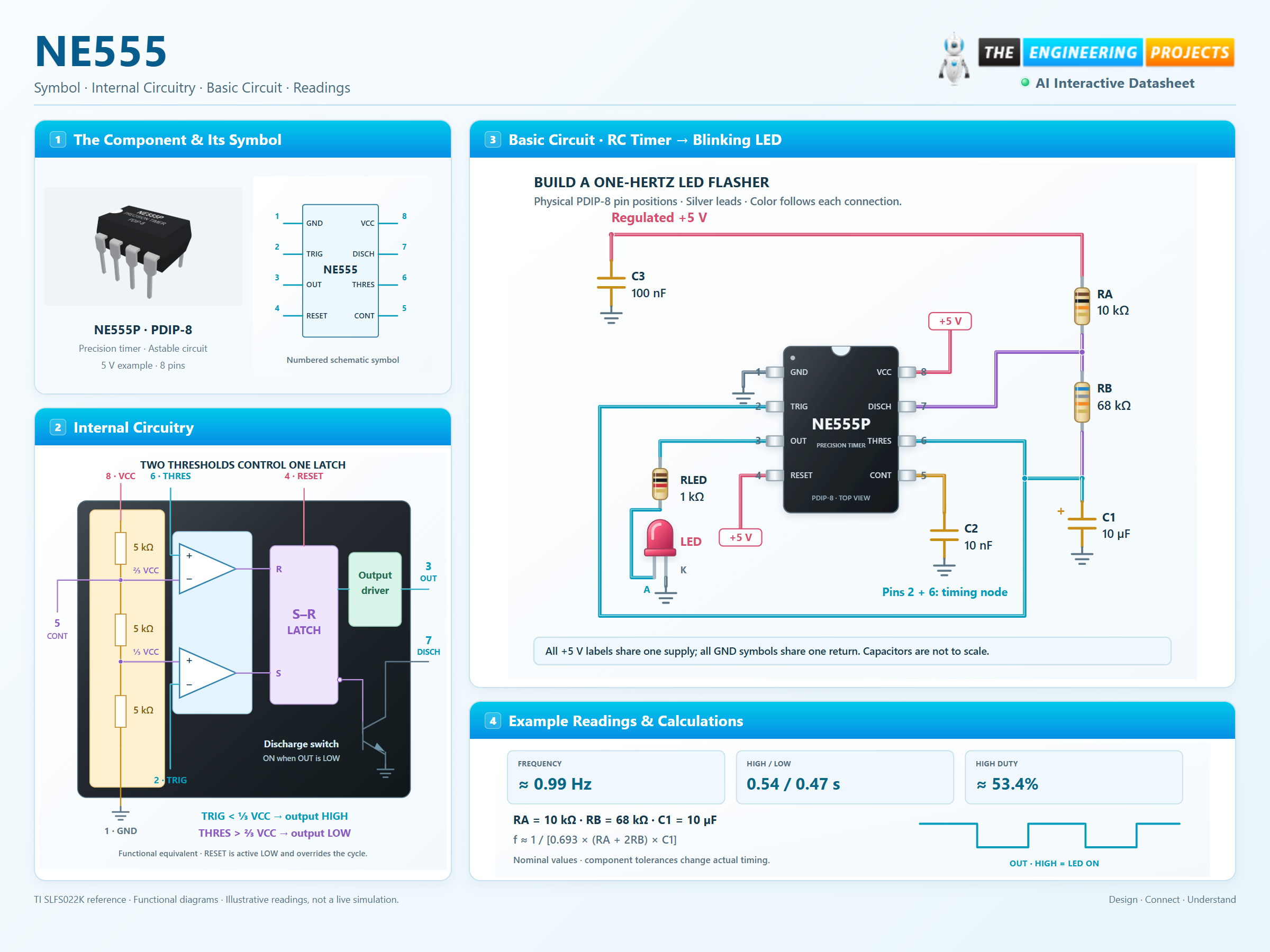
Connect pins 8 and 4 to +5 V, pin 1 to ground. Use a 100 nF supply bypass and a 10 nF capacitor from CONT to ground.
Build the timing network
RA = 10 kΩ, RB = 68 kΩ and C1 = 10 µF. Join pins 2 and 6 to the capacitor node; pin 7 connects to the resistor junction. The capacitor’s positive plate faces the timing node.
Read the cycle
Nominal high time is 0.693 × (RA + RB) × C1 = 0.541 s. Low time is 0.693 × RB × C1 = 0.471 s. The LED flashes about once per second; tolerance changes the exact result.
Step 1 of 3