 BETA
Power and bypass
Connect 5 V and ground and fit the local bypass capacitor.
Build a basic DHT11 circuit with labeled pins, component values and connection guidance.
A vented sensor, one pullup and a controller with compatible logic.
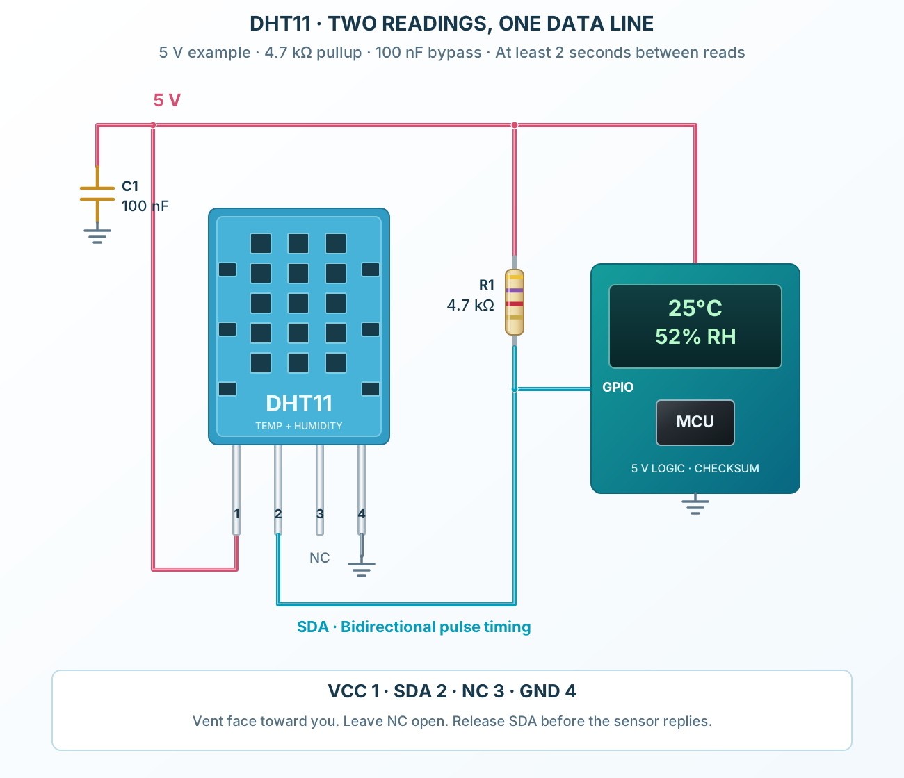
Follow the component values and pin connections
Connect 5 V and ground and fit the local bypass capacitor.
Connect SDA to a compatible GPIO through a short connection with a 4.7 kΩ pullup.
Observe the start and pulse timings, check all five bytes, and wait at least two seconds between reads.