Hello friends, I hope you all are doing great. Today, I am going to share the new Flame Sensor Library for Proteus V2.0. The flame sensor is the small blue module with a black infrared receiver on long legs: it sees the infrared light of a flame and tells your Arduino about it through an analog output (A0) and a digital output (D0). With this Flame Sensor Library for Proteus, you light a candle, a lighter or a gas burner in the simulation, move it closer or turn the sensor away, switch on the sun, and your Arduino reads the module just as it reads a real one, with analogRead() and digitalRead().
We shared earlier versions of a flame sensor library for Proteus before. Version 2.0 is a completely new model with its own files: the sensor is now a real analog part in the SPICE simulator of Proteus, and you get two devices: Flame Simple, with a live scene panel on the schematic, and Flame Advance, with a pop-up window and four measured flame sensor test tools. The new Flame Sensor Arduino Proteus demo is a fire alarm on two Arduino UNOs, shown in the compact Simple interface of our TEP Serial Monitor.
NOTICE: This library is very special to our team. Our flame sensor is a real analog part: the board's A0 divider and the LM393's open-collector D0 output are node voltages in the SPICE simulator of Proteus, with a flickering flame, a flame that grows when you light it, the receiver's 60 degree view and the sunlight that fools the real module. It took our team a lot of hard work, many test runs and many design changes. Your feedback is the fuel that keeps us going, so please tell us what you think in the comments below or in the Flame Sensor Library board of our forum. And if our free libraries help you, you can buy us a coffee. So, let's get started with the Flame Sensor Library for Proteus V2.0:
What is a Flame Sensor Module?
A flame sensor module, also called an IR flame sensor, detects the infrared (IR) light that every flame gives off. Infrared is light with a longer wavelength than red, which our eyes cannot see. The module's eye is a black 5 mm IR receiver, usually a YG1006 phototransistor, that responds to light from about 760 to 1100 nm. It stands on long legs at one end of a small blue board (about 31 x 14 mm), so you can bend it towards the place you want to watch.
On the board, an LM393 comparator, a blue potentiometer (pot), a PWR LED and a D0 LED do the rest. A comparator compares two voltages and switches its output depending on which one is higher. So the module has two outputs:
- A0, an analog voltage. It is LOWER when there is MORE infrared, so a stronger or closer flame gives a lower A0. On an Arduino UNO, it reads about 1021 with no infrared at all and goes down to about 20 when the receiver is saturated.
- D0, a digital output. It goes LOW, and the D0 LED lights, while the infrared is stronger than the level you set with the pot; otherwise it is HIGH.
Flame sensors are used in hobby fire alarms and in fire-fighting robots that drive towards a candle. Many beginners expect A0 to rise with a bigger flame; on almost every board it falls.
The Flame Sensor Module at a Glance
| Feature | Value |
|---|---|
| Detects | The infrared light of a flame, about 760 to 1100 nm |
| Receiver | A black 5 mm IR receiver on long legs (usually a YG1006 phototransistor) |
| Comparator | LM393, with a blue pot for the trip level |
| Outputs | A0 (analog, lower = more infrared) and D0 (digital, LOW = flame) |
| LEDs | PWR (power) and D0 (lit while D0 is LOW) |
| Pins | VCC, GND, D0, A0 on a 4-pin header |
| Supply | 3.3 to 5 V; A0 and the pot's reference follow VCC |
| View angle | About 60 degrees |
| Range | A lighter at about 80 cm; a bigger flame further away (the pot sets it) |
| Board | Blue PCB, about 31 x 14 mm, portrait |
Flame Sensor Terms You Will See in This Article
| Term | Meaning |
|---|---|
| IR (infrared) | Light our eyes cannot see; every flame gives off a lot of it |
| A0 | The analog output; a lower voltage means more infrared |
| D0 | The digital output of the LM393; LOW = flame detected |
| ADC count | The number analogRead() returns: 0 to 1023 for 0 to 5 V on an UNO |
| IR level | How strongly the receiver responds, 0 to 100 %; the demo sketch computes it from the ADC count |
| Pot, trip level | The blue potentiometer: it sets the IR level at which D0 goes LOW |
| Reference (POT) | The voltage the LM393 compares A0 with: 2.54 V at the middle pot setting |
| Hysteresis | A gap between the switch-on and the switch-off point; this board has none |
| Flicker | The fast, random brightness change of a real flame, about 1 to 20 Hz |
| False alarm | D0 going LOW without a flame, for example in sunlight |
How the Flame Sensor Turns Infrared Into A0 and D0
A0: a Voltage Divider
On the board, a 10 k resistor pulls the A0 node up to VCC, and the IR receiver pulls it down to ground. More infrared makes the receiver conduct more, so A0 drops. Our model builds exactly this divider in the SPICE simulator of Proteus, so your Arduino reads a real node voltage.
D0: the LM393 Comparator
The LM393 compares A0 with the pot's voltage, the reference. While A0 is below it, its open-collector output pulls D0 LOW and the D0 LED lights; otherwise the board's 10 k pull-up keeps D0 HIGH. At the middle pot setting, D0 goes LOW above an IR level of 50 %, which is A0 below 2.54 V. There is no hysteresis, so a flickering flame right at the trip level makes D0 chatter, as on a real module.
The IR Level, the Distance and the Angle
Our model computes the infrared intensity I from the flame's power divided by the distance squared, times the angle response, plus the ambient light. The receiver's response, the IR level, is I / (I + 1), from 0 to 100 %, and A0 = VCC x (1020 - 10 x level) / 1023.
- Distance: 6 to 100 cm. At the middle pot setting, D0 trips for a candle up to 50 cm, for a lighter up to 80 cm and for a gas burner up to 150 cm.
- Angle: half the infrared at 30 degrees off axis, and none from 60 degrees: the "60 degree view".
- Ambient light: a dark room adds nothing, indoor light a little, and sunlight enough to trip D0 at the middle pot setting.
- Flicker: A0 ripples with three tones of 3.1, 7.3 and 12.7 Hz, like a real flame. FLICKER OFF gives steady values.
- Ignition: a flame you light while the simulation runs grows (a candle in about 1.2 s, a lighter in 0.15 s, a burner in 0.4 s: our model's times, not data sheet values) and fades in 30 to 50 ms when you put it out.
In numbers, on an UNO at 5 V: no flame in a dark room reads 1021, indoor light 1001, a candle at 30 cm 284 (with the flicker off), and sunlight alone 270.
What's New in Flame Sensor Library for Proteus V2.0
Version 2.0 is a new library with its own parts and files (TEPFLAME.LIB and TEPFLAME.DLL). Here is what it brings:
- Two devices in
TEPFLAME.LIB: Flame Simple (FLAMETEP) and Flame Advance (FLAMEADVTEP). - A real analog model: A0 and D0 are node voltages in the SPICE simulation.
- A new board in the real module's shape, with a glowing receiver, IR wave arcs and a "what the sensor sees" window.
- Ignition: a flame lit at run time grows, and one put out fades.
- Panels that show what your sketch reads: the UNO's ADC count and the demo's IR level.
- A D0 pin log, a live 10 s A0 chart and four measured test tools on the Advance.
- A two-UNO fire alarm demo with the TEP Serial Monitor instead of the Virtual Terminal, with the commands HELP, STATUS, READ, EVERY, ALARM and AVG.
- A light package: about 1.46 MB, without the C++ source code.
Flame Sensor Library for Proteus: Simple vs Advance
Both devices run the same model with the same properties; only the panel differs:
| Feature | Simple | Advance |
|---|---|---|
| Full analog flame sensor model (A0 divider, LM393 D0, flicker, ignition, sunlight, the 60 degree view) | ✔ | ✔ |
| Blue board with the receiver, the "what the sensor sees" window, IR arcs, PWR / D0 LEDs | ✔ | ✔ |
| FLAME SCENE panel on the schematic (side view, A0 vs POT gauge, three rows of buttons) | ✔ | ✘ |
| Pop-up window you can move, resize and minimise | ✘ | ✔ |
| Scene page: a distance slider from 6 to 100 cm, a live A0 chart of 10 s and the D0 pin log | ✘ | ✔ |
| Range sweep, D0 threshold, Step response and Sunlight test | ✘ | ✔ |
| TEP Dark / Light theme, text size, Help page with Copy diagnostics | ✘ | ✔ |
| PANEL property: the panel open or closed at the start | ✔ | ✘ |
Choose Simple to keep the scene beside your circuit, and Advance when your sheet is full or you want hard numbers about your sensor and your sketch. The demo has one of each.
Download Flame Sensor Library for Proteus
Click the button below to download Flame-Sensor-Library-for-Proteus-v2.0.zip (about 1.46 MB, without the C++ source code):
Flame Sensor Library for Proteus V2.0- README.txt: a detailed guide to the files, the wiring, the model, the test tools and real hardware.
- Proteus Library Files:
TEPFLAME.LIB(both devices),TEPSERIALMON.LIBand our Arduino UNO libraryArduinoV3TEP.LIB/ArduinoV3TEP.IDX. - Proteus Model Files:
TEPFLAME.DLLandTEPSERIALMON.DLL. - Proteus Simulation:
Flame-Sensor-ArduinoUnoV3.pdsprj,Flame_Alarm.hex(both UNOs run it) and copies of both DLLs. - Arduino Code:
Flame_Alarm.ino, the demo sketch. It needs no extra Arduino library.
The zip holds 12 files in one folder, FLAME-TEP-v2.0.
How to Install Flame Sensor Library for Proteus
- Close Proteus and extract the whole zip file to a normal folder, for example on your Desktop.
- Copy the four files from Proteus Library Files into the LIBRARY folder of Proteus, usually
C:\Program Files (x86)\Labcenter Electronics\Proteus 8 Professional\LIBRARY(on some PCsC:\ProgramData\Labcenter Electronics\Proteus 8 Professional\LIBRARY: use the folder that already holds the .LIB files that came with Proteus). - Copy
TEPFLAME.DLLandTEPSERIALMON.DLLinto the MODELS folder. - If a
TEPFLAME.IDXfile is in the LIBRARY folder, delete it. - Start Proteus, press P (Pick Devices) and search for Flame. You get the Simple and the Advance device (Pick Devices category Sensors, sub-category Temperature).
Tip: the Proteus Simulation folder has its own copies of both DLLs, so keep them and the .hex file beside the demo project. The library was tested in Proteus 8.5; Proteus 7 is not supported.
The Flame Sensor Board in Proteus
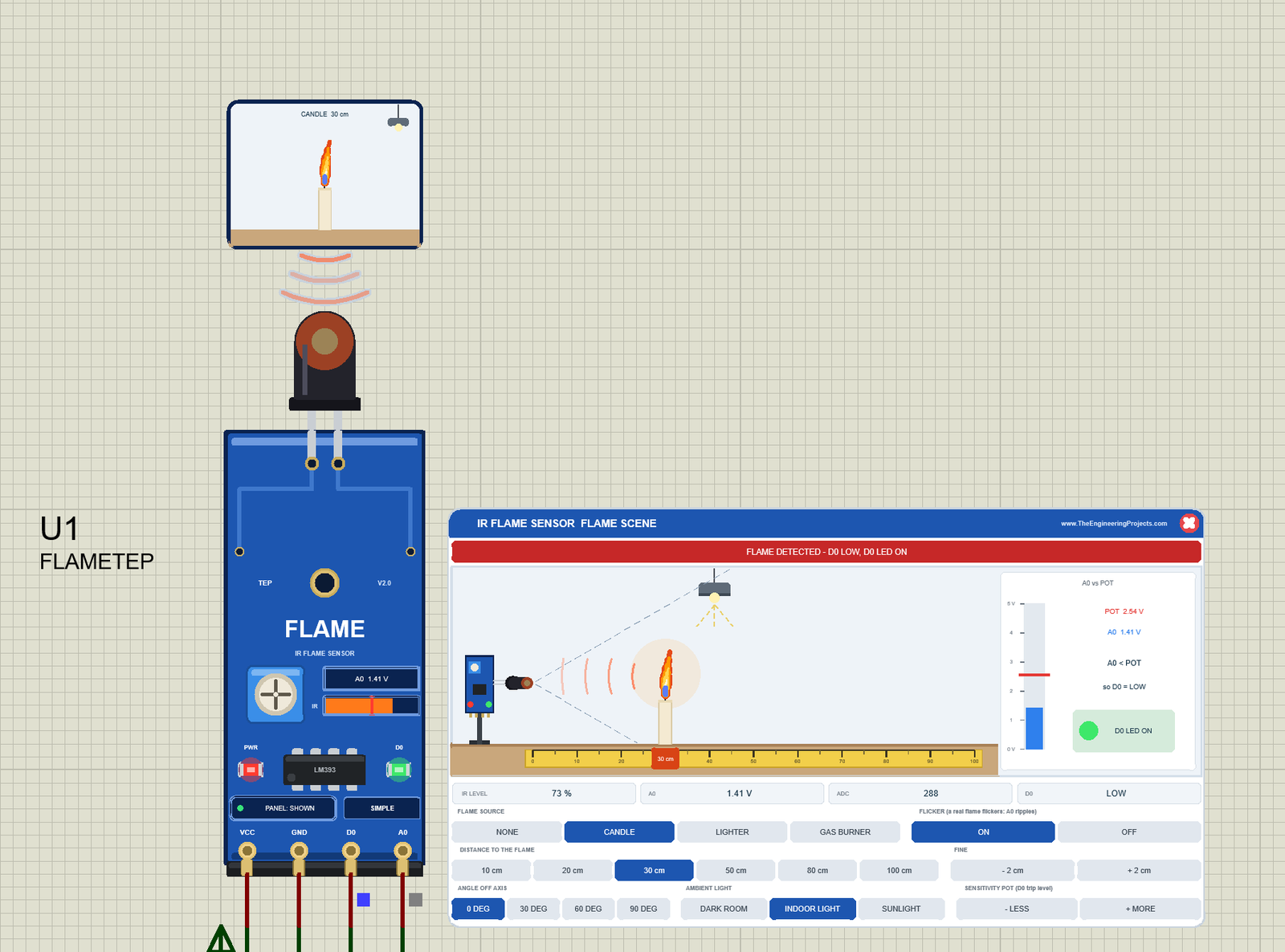
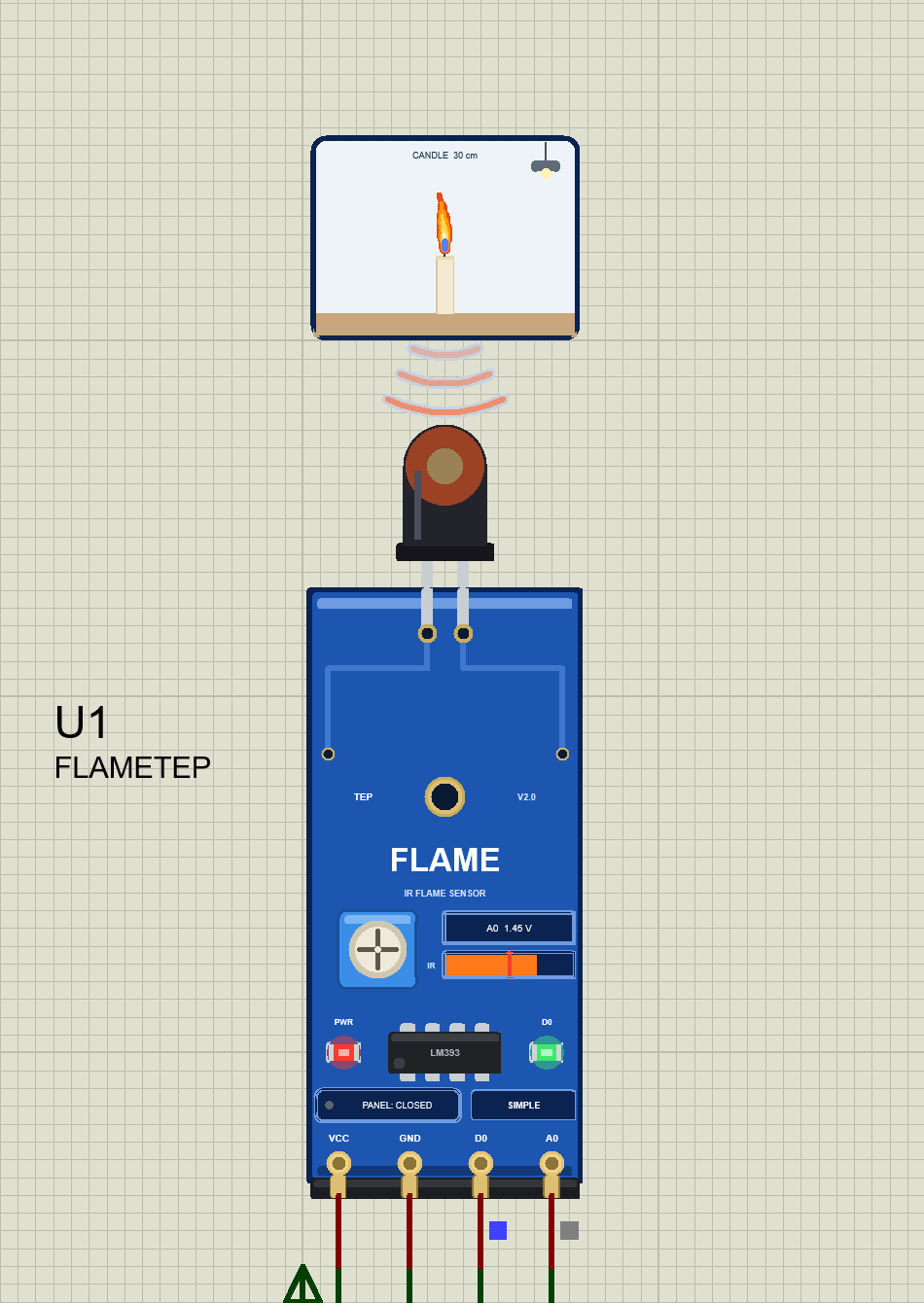
We drew the module as a clean TEP board in the blue of the real one and in its real proportions: portrait, 31 x 14 mm, with the 4-pin header at the bottom and the black receiver standing over the top edge on its long legs. Here is U1, the Simple device, with the start scene, a candle at 30 cm:
What the Sensor Sees
While the simulation runs, the receiver's dome glows orange with the infrared, and three arcs ripple down into it in the colour of the flame. The window above them shows the scene from the sensor's point of view: the flame on its table, with the room lamp or the sun. The flame grows when you light it, flickers, gets smaller far away and moves aside when you turn the sensor. Its label says "CANDLE 30 cm" here; others are OUT OF VIEW, LIGHTING and NO FLAME.
Pinout
The four pins keep the order most boards print on their header:
| Pin | What it does | Demo connection |
|---|---|---|
| VCC | Power, 3.3 to 5 V | 5 V supply terminal |
| GND | Ground | Ground |
| D0 | Digital output of the LM393: LOW = flame (the D0 LED lights) | Arduino A1, used as a digital input |
| A0 | Analog output: lower = more infrared | Arduino A0 |
LEDs and Indicators
| Indicator | On the real board? | What it shows |
|---|---|---|
| PWR LED (red) | Yes | Lit while the board has power |
| D0 LED (green) | Yes | Lit while D0 is LOW: flame detected |
| Receiver dome | Yes (the glow is our animation) | Glows orange with the infrared |
| Blue pot | Yes | Its rotor turns with the trip level |
| IR level bar | TEP addition | The demo's IR level in orange, the trip level as a red mark |
| A0 box | TEP addition | The live A0 voltage, for example "A0 1.41 V" |
| Three IR arcs | TEP addition | A ripple in the flame's colour travels down while infrared arrives |
| "What the sensor sees" window | TEP addition | The flame, its distance and angle, the lamp or the sun |
| PANEL / OPEN PANEL, SIMPLE / ADVANCE | TEP addition | The panel button and the device badge |
The PWR and D0 LEDs, the pot and the receiver are on the real module. The IR bar, the A0 box, the arcs, the window and the button are TEP additions: the real board has no display.
Component Properties
| Property | Meaning | Default |
|---|---|---|
| SOURCE | The flame at the start: NONE, CANDLE, LIGHTER, GAS BURNER | CANDLE |
| DISTANCE | Distance to the flame in cm, 6 to 100 | 30 |
| ANGLE | Degrees the sensor is turned away from the flame, 0 to 90 | 0 |
| AMBIENT | DARK, INDOOR or SUNLIGHT | INDOOR |
| FLICKER | ON or OFF | ON |
| THRESHOLD | The pot's trip level as an IR level, 5 to 95 %; lower = more sensitive | 50 |
| PANEL | Simple only: the panel at the start, OPEN or CLOSED | OPEN |
Every Run starts again from these properties; the panel's clicks last until the simulation stops. The panel style comes from the device (Simple or Advance), not from a property.
Flame Sensor Simple: The FLAME SCENE Panel on the Sheet
Beside the Simple board sits the FLAME SCENE panel (on the right of the image above). It shows the scene from the side and has a button for everything you can change:
| Part | What it does |
|---|---|
| Header, red X | IR FLAME SENSOR FLAME SCENE and our website; the X closes the panel |
| Banner | The state in words: NO FLAME, FLAME TOO WEAK OR TOO FAR, FLAME OUTSIDE THE 60 DEG VIEW, FLAME DETECTED, SUNLIGHT - POSSIBLE FALSE ALARM or NO POWER |
| Side view | The sensor on its stand, the flame on a table with a 0 to 100 cm tape, the receiver's view as two dashed lines, IR heat waves, and the ceiling lamp or the sun |
| A0 vs POT | A 0 to 5 V gauge with A0 (blue) and the pot's reference (red line), the comparator's decision and a D0 LED lamp |
| Readouts | IR LEVEL, A0, ADC and D0 |
| FLAME SOURCE | NONE, CANDLE, LIGHTER, GAS BURNER |
| FLICKER | ON / OFF ("a real flame flickers: A0 ripples") |
| DISTANCE TO THE FLAME, FINE | 10, 20, 30, 50, 80, 100 cm, and - 2 cm / + 2 cm |
| ANGLE OFF AXIS | 0, 30, 60, 90 DEG |
| AMBIENT LIGHT | DARK ROOM, INDOOR LIGHT, SUNLIGHT |
| SENSITIVITY POT (D0 trip level) | - LESS and + MORE, in 5 % steps |
The selected buttons are dark blue. The readouts show what your sketch reads: the UNO's ADC count and the demo's IR level. In the image above, A0 (1.41 V, blue) is below the pot's red line (2.54 V), so the gauge says "A0 < POT" and "so D0 = LOW", and its D0 LED lamp is on.
LIGHTER: More Infrared, a Lower A0
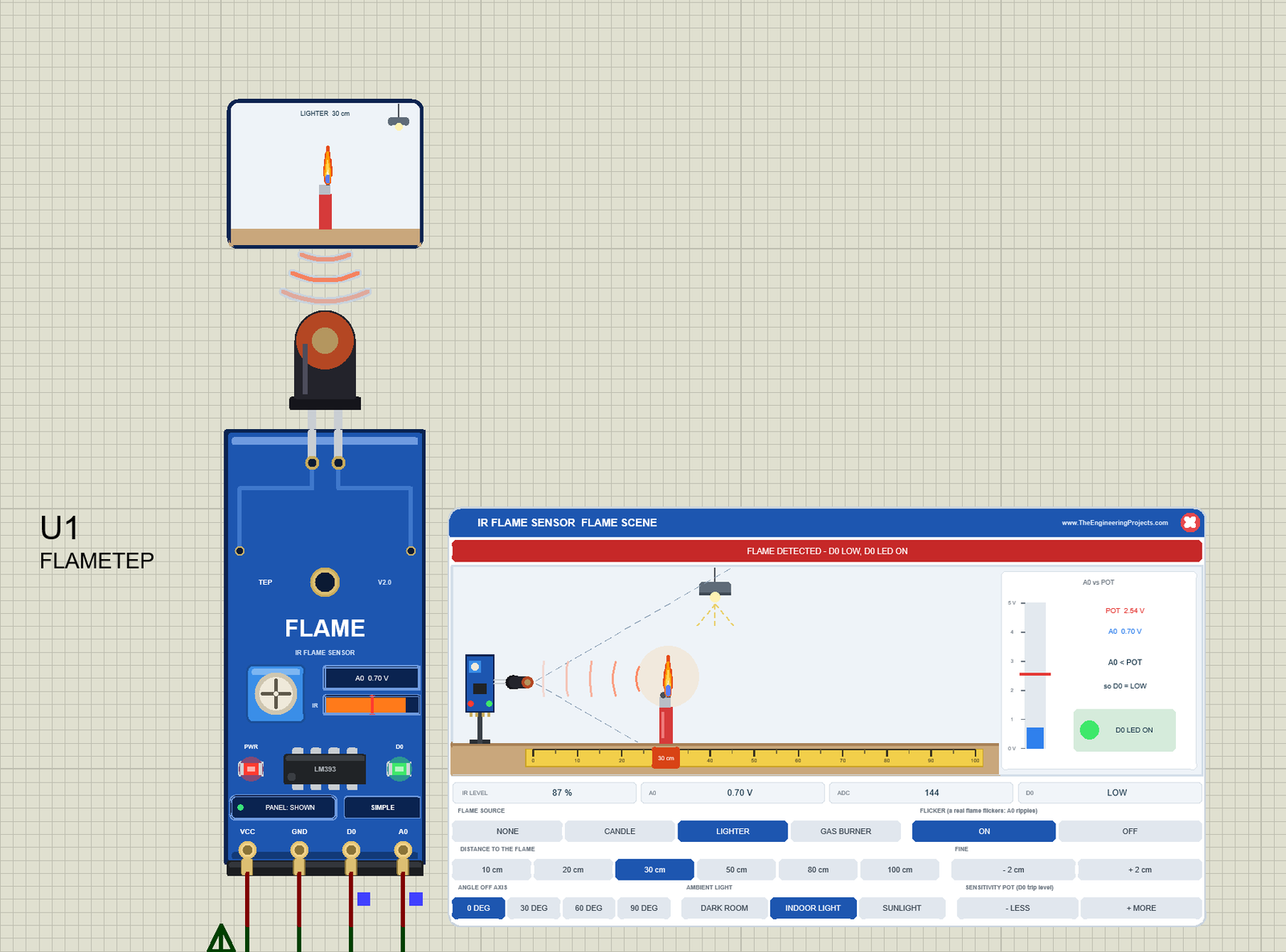
Click LIGHTER. A lighter's flame gives off more infrared than a candle's, so at the same 30 cm, A0 falls from 1.41 V to 0.70 V, the ADC from about 288 to 144, and the IR level rises to 87 %. The IR bar on the board fills up, and the window shows the red lighter.
Out of View in a Dark Room
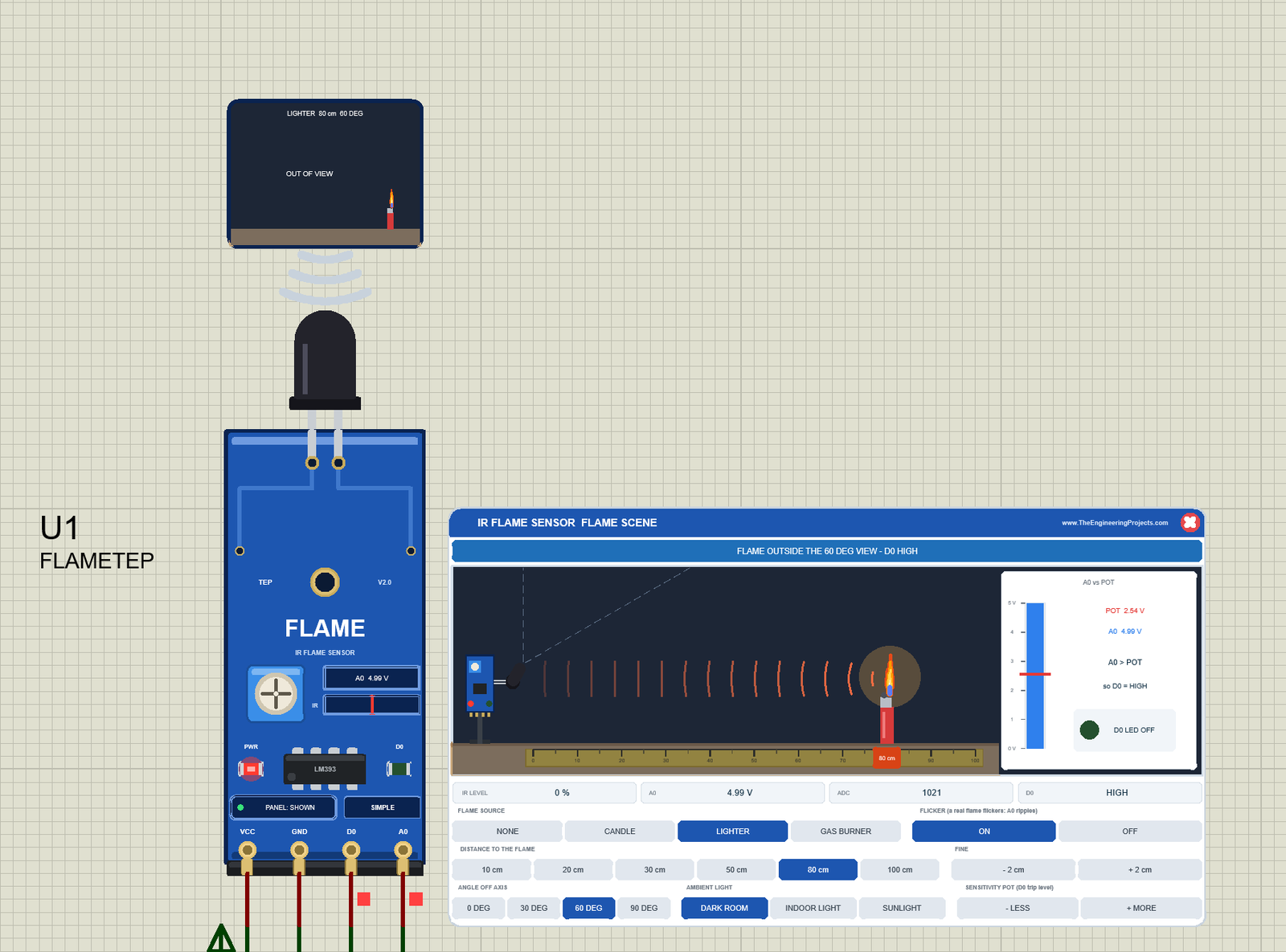
Now click 80 cm, 60 DEG and DARK ROOM. The sensor in the side view turns away, the scene goes dark, and the blue banner says FLAME OUTSIDE THE 60 DEG VIEW - D0 HIGH. The IR level is 0 %, A0 is 4.99 V and the ADC 1021: the same as no flame at all. The gauge says "A0 > POT", the receiver's dome is dark, and the window says OUT OF VIEW, with the small lighter at its edge. A real module behaves the same way, so point it at the place where a fire could start.
SUNLIGHT: the Classic False Alarm
Click NONE (no flame) and SUNLIGHT. Sunlight carries a lot of infrared: the IR level jumps to about 75 %, the ADC to 270, and D0 goes LOW at the middle pot setting. The banner says SUNLIGHT - POSSIBLE FALSE ALARM, and the Serial Monitor prints "IR level: 75 % ADC: 270 D0: LOW FIRE! Flame detected" with no flame at all. This is exactly what a real module does near a window. The Sunlight test below finds the pot setting that ignores the sun.
The Pot: - LESS and + MORE
The SENSITIVITY POT buttons change the trip level in 5 % steps. + MORE makes the sensor more sensitive (a lower trip level, a longer range), like turning the real pot clockwise; - LESS does the opposite. The pot's rotor, the red mark on the IR bar and the gauge's red line move with it. A0 does not depend on the pot; only D0 does.
Closing the Panel
Click the red X in the panel's header: the panel disappears, the board button says PANEL: CLOSED, and the sensor keeps working. Click PANEL to bring the panel back.
Flame Sensor Advance: The Pop-Up Window
The Advance device keeps only the board on the schematic. Here is U2:
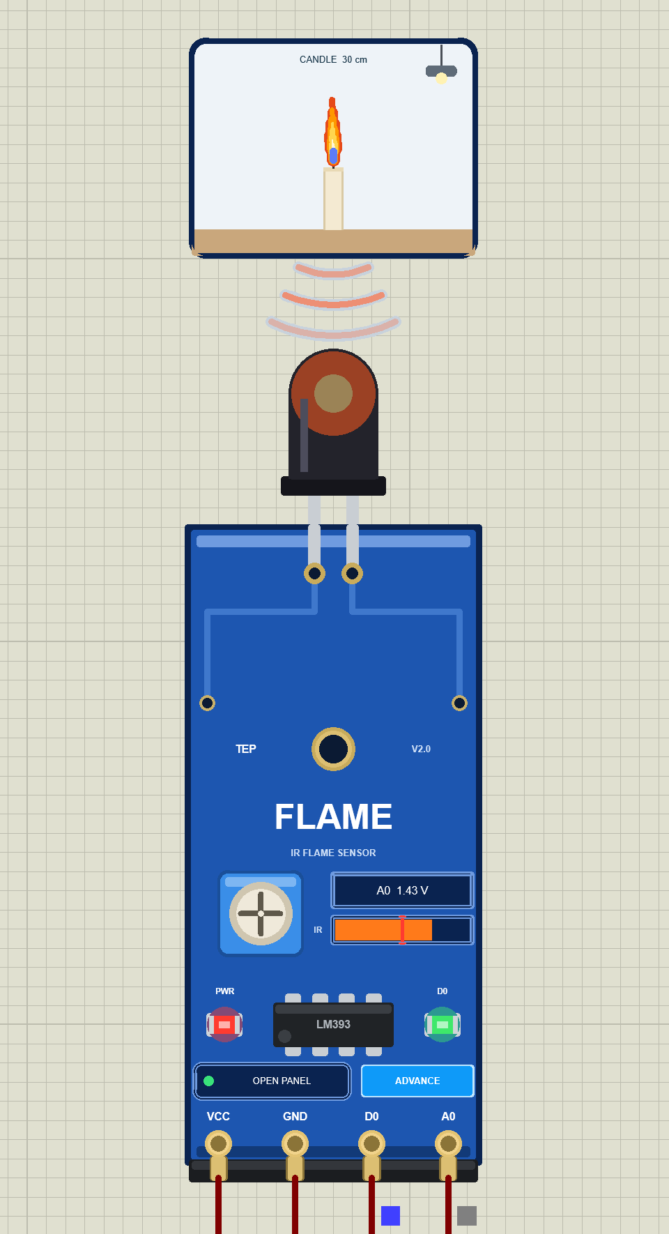
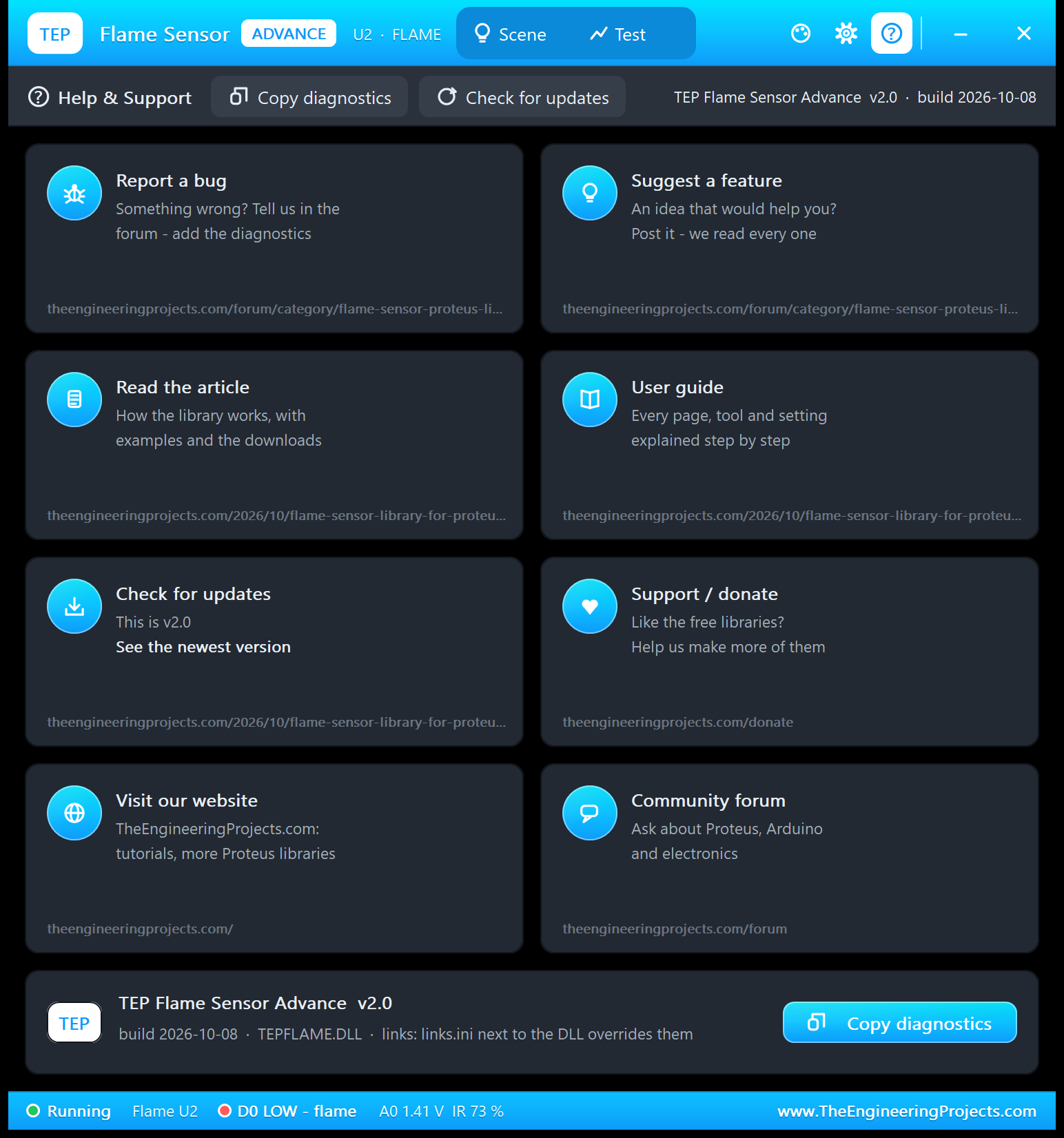
At Run, the "TEP Flame Sensor Advance" pop-up opens with the look of our TEP Serial Monitor and no Windows title bar: move it by its header, resize or minimise it, and open it again with OPEN PANEL after you close it. The header shows the state (here U2 · FLAME; the others are NO FLAME, TOO WEAK, OFF AXIS, SUN ALARM, LIGHTING, TESTING and NO POWER), the Scene and Test tabs, and the palette (theme), gear (Settings) and ? (Help) icons.
The Scene Page
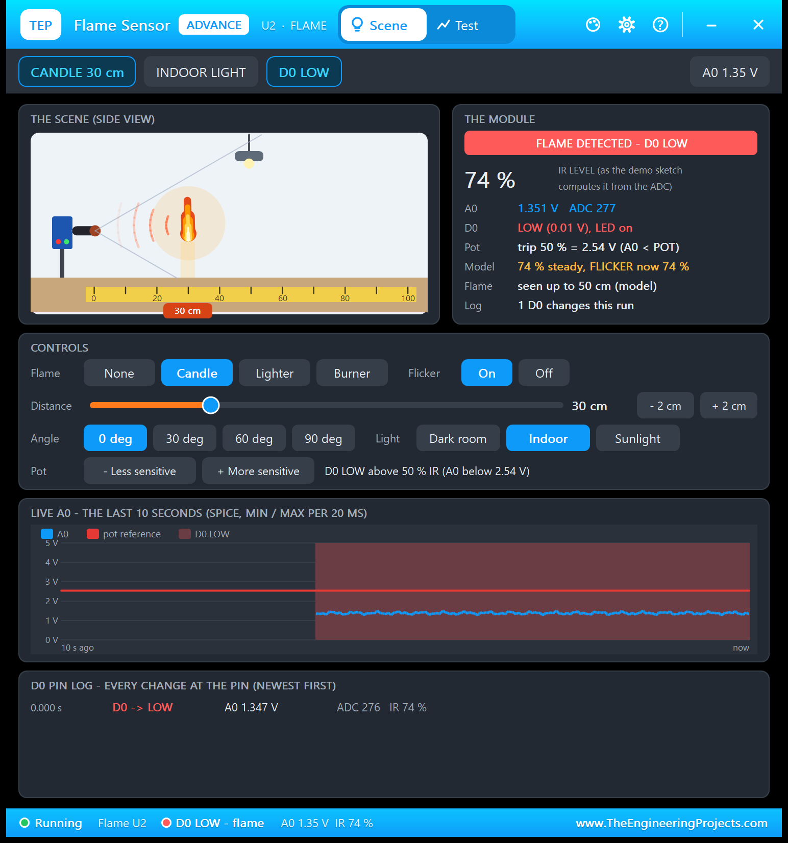
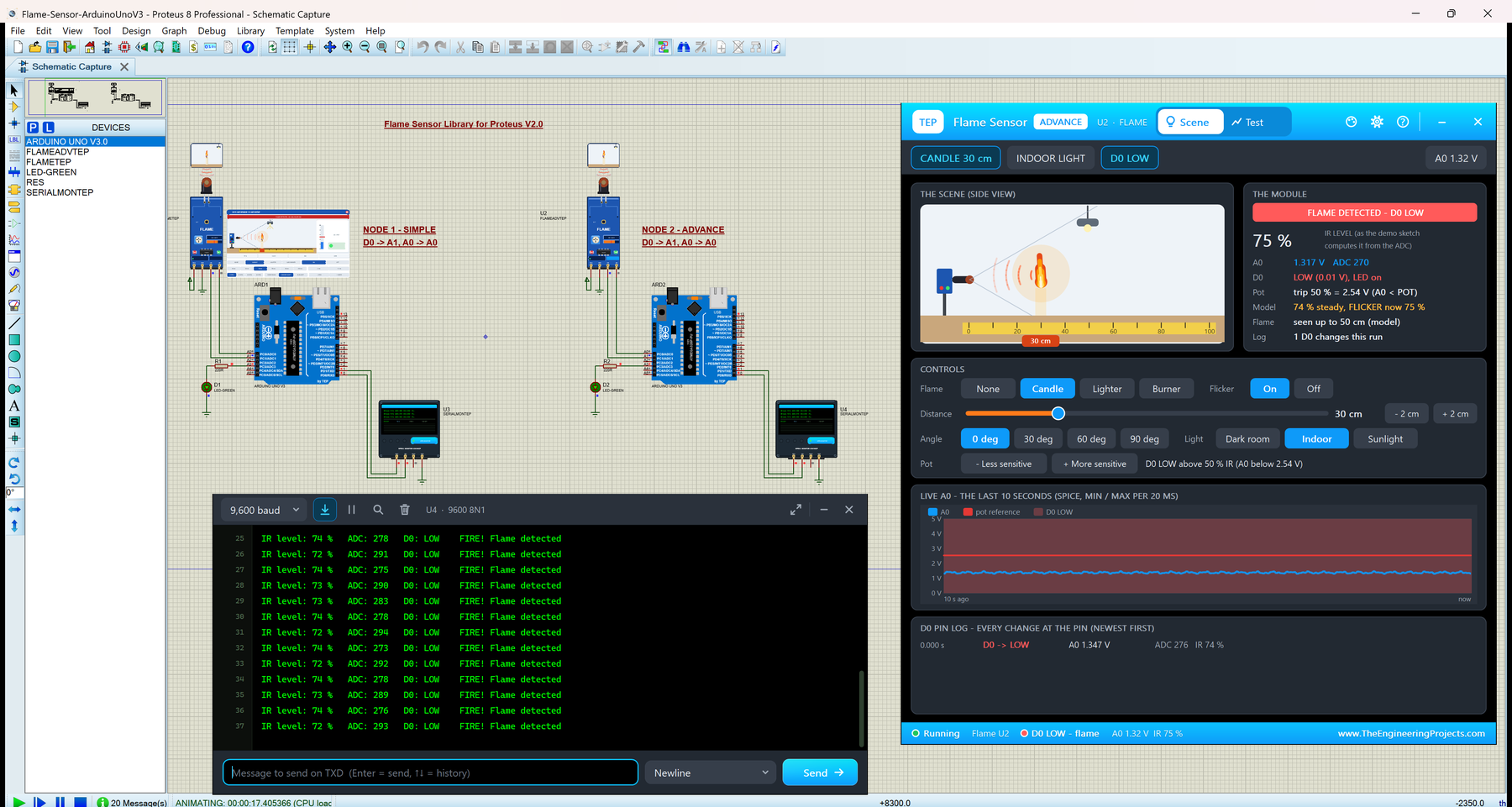
- Toolbar chips: CANDLE 30 cm, INDOOR LIGHT, D0 LOW and the live A0 (1.35 V).
- THE SCENE (SIDE VIEW): the same side view as on the Simple panel.
- THE MODULE: the banner (FLAME DETECTED - D0 LOW), the IR level as the demo sketch computes it (74 %), A0 1.351 V with ADC 277, D0 LOW (0.01 V) with its LED on, the pot "trip 50 % = 2.54 V (A0 < POT)", "74 % steady, FLICKER now 74 %", "seen up to 50 cm (model)" and the D0 changes in this run.
- CONTROLS: Flame, Flicker, a distance slider from 6 to 100 cm with - 2 cm / + 2 cm, Angle, Light and the pot (- Less sensitive, + More sensitive).
- LIVE A0 - THE LAST 10 SECONDS: the A0 node voltage, as the minimum and maximum of every 20 ms, with the pot's reference as a red line and the time D0 was LOW shaded. The flicker shows as a small ripple.
- D0 PIN LOG: every change of D0 with its time, A0, ADC and IR level. Here there is one: D0 went LOW at 0.000 s, with A0 at 1.347 V (ADC 276, IR 74 %).
In the featured image, the same page shows 75 % and ADC 270 a moment later: the flicker moves A0 a little, while the steady value stays at 74 %.
The Test Page: Four Measured Flame Sensor Test Tools
The four tools on the Test tab take the scene over while they run, measure the A0 and D0 node voltages at every simulation step, and put the scene back when they end. So every number is what the circuit really did, timed with the simulation clock. Each tool ends with a bold "Good for:" line. All results below come from U2, with the demo sketch reading at the same time.
1. Range Sweep: How Far Does Your Sensor See a Flame?
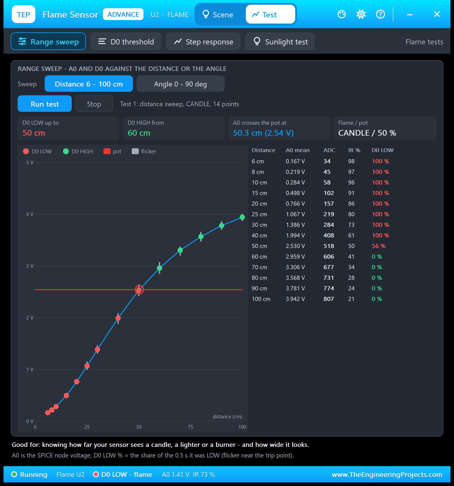
Good for: "knowing how far your sensor sees a candle, a lighter or a burner - and how wide it looks." Choose Distance 6 - 100 cm or Angle 0 - 90 deg and click Run test. The tool uses the scene's flame, light and pot, steps the flame over 14 distances (or 10 angles), waits 0.12 s at each point and measures for 0.5 s: the mean A0, the ADC count, the demo's IR level and how much of the time D0 was LOW.
| Distance | A0 mean | ADC | IR % | D0 LOW |
|---|---|---|---|---|
| 6 cm | 0.167 V | 34 | 98 | 100 % |
| 8 cm | 0.219 V | 45 | 97 | 100 % |
| 10 cm | 0.284 V | 58 | 96 | 100 % |
| 15 cm | 0.498 V | 102 | 91 | 100 % |
| 20 cm | 0.766 V | 157 | 86 | 100 % |
| 25 cm | 1.067 V | 219 | 80 | 100 % |
| 30 cm | 1.386 V | 284 | 73 | 100 % |
| 40 cm | 1.994 V | 408 | 61 | 100 % |
| 50 cm | 2.530 V | 518 | 50 | 56 % |
| 60 cm | 2.959 V | 606 | 41 | 0 % |
| 70 cm | 3.306 V | 677 | 34 | 0 % |
| 80 cm | 3.568 V | 731 | 28 | 0 % |
| 90 cm | 3.781 V | 774 | 24 | 0 % |
| 100 cm | 3.942 V | 807 | 21 | 0 % |
At 30 cm, A0 is 1.386 V, ADC 284 and 73 %, the numbers the demo prints. D0 stays LOW all the time up to 40 cm. At 50 cm, it is LOW only 56 % of the time: A0 (2.530 V) sits right at the pot's 2.54 V, and the flicker moves it above and below. From 60 cm on, D0 stays HIGH, and A0 crosses the pot at 50.3 cm. In the chart, red dots are D0 LOW points, green dots D0 HIGH, and the grey whiskers show the flicker. The angle sweep works the same way; in our PC tests with a candle at 30 cm, D0 stayed LOW up to 30 degrees and went HIGH from 40 degrees.
2. D0 Threshold: Where Exactly Does D0 Switch?
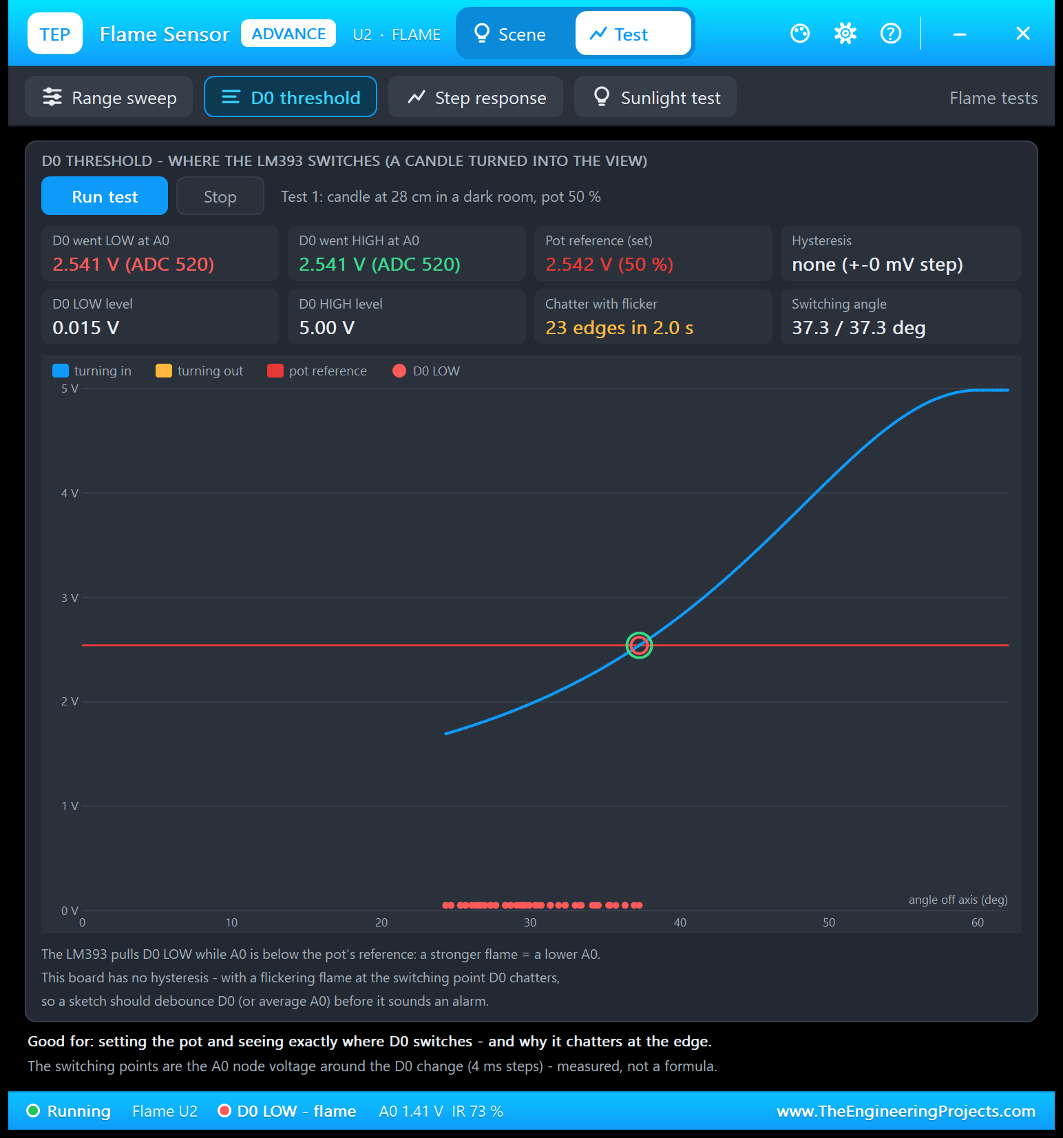
Good for: "setting the pot and seeing exactly where D0 switches - and why it chatters at the edge." The tool puts a candle at 28 cm in a dark room and turns the sensor into the view at 20 degrees per second and out again, with the flicker off, while it watches A0 at the moment D0 changes. Then it holds the switching angle for 2 s with the flicker on and counts the D0 edges.
| Result | Value |
|---|---|
| D0 went LOW at A0 | 2.541 V (ADC 520) |
| D0 went HIGH at A0 | 2.541 V (ADC 520) |
| Pot reference (set) | 2.542 V (50 %) |
| Hysteresis | none (+-0 mV step) |
| D0 LOW level / HIGH level | 0.015 V / 5.00 V |
| Chatter with flicker | 23 edges in 2.0 s |
| Switching angle | 37.3 / 37.3 deg |
D0 goes LOW and back HIGH at the same A0 voltage, right at the pot's reference, measured in 4 ms simulation steps: the board has no hysteresis. So with a flickering flame at the switching angle, D0 changed 23 times in 2 seconds. The blue line shows A0 against the angle, and the red dots mark where D0 was LOW. The tool's own advice: debounce D0 (or average A0) before you sound an alarm.
3. Step Response: How Fast Does Your Alarm React?
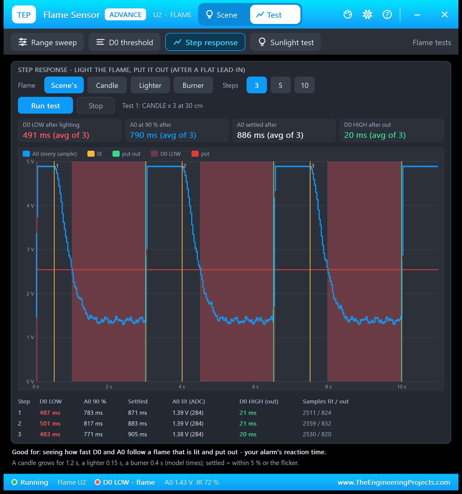
Good for: "seeing how fast D0 and A0 follow a flame that is lit and put out - your alarm's reaction time." Choose the flame (the Scene's, Candle, Lighter or Burner) and 3, 5 or 10 steps. The tool first waits until A0 is flat with no flame, for at least 0.5 s, then lights the flame and puts it out again, keeping every sample:
| Step | D0 LOW | A0 90 % | Settled | A0 lit (ADC) | D0 HIGH (out) | Samples lit / out |
|---|---|---|---|---|---|---|
| 1 | 487 ms | 783 ms | 871 ms | 1.39 V (284) | 21 ms | 2511 / 824 |
| 2 | 501 ms | 817 ms | 883 ms | 1.39 V (284) | 21 ms | 2559 / 832 |
| 3 | 483 ms | 771 ms | 905 ms | 1.38 V (284) | 20 ms | 2530 / 820 |
The candle grows for about 1.2 s (a model time), so A0 falls in a smooth curve: D0 goes LOW after about half a second, when A0 passes the pot's red line. "Settled" means within 5 % of the step or within the flicker. Putting the flame out is fast: D0 is HIGH again after about 20 ms. Add the demo's 500 ms reading interval, and the sketch reports a newly lit candle about 0.5 to 1 s after it was lit.
4. Sunlight Test: Will Daylight Set Off Your Fire Alarm?
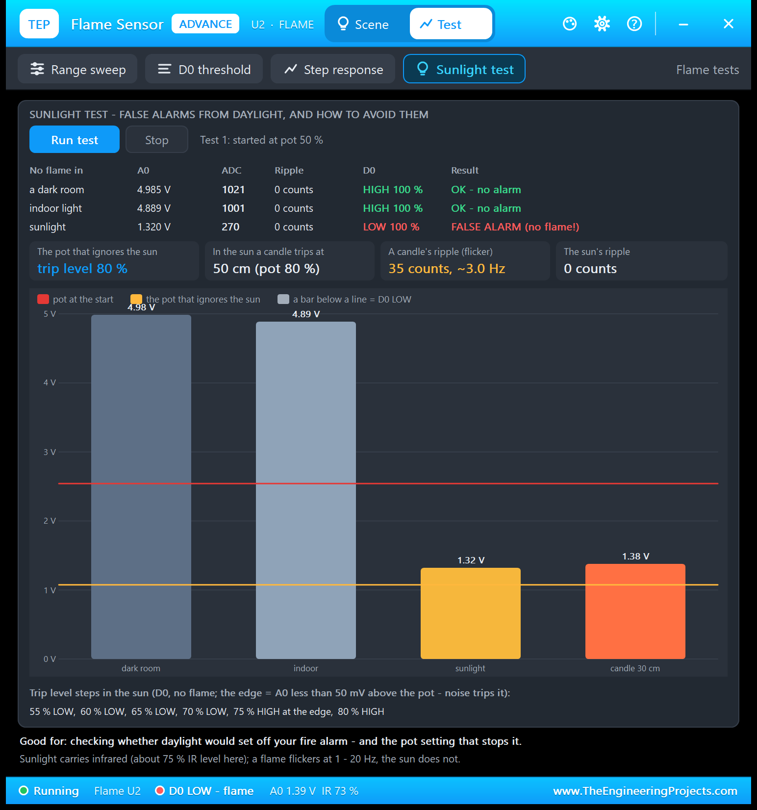
Good for: "checking whether daylight would set off your fire alarm - and the pot setting that stops it." The tool starts without a flame: it measures A0, its ripple and D0 in a dark room, in indoor light and in sunlight:
| No flame in | A0 | ADC | Ripple | D0 | Result |
|---|---|---|---|---|---|
| a dark room | 4.985 V | 1021 | 0 counts | HIGH 100 % | OK - no alarm |
| indoor light | 4.889 V | 1001 | 0 counts | HIGH 100 % | OK - no alarm |
| sunlight | 1.320 V | 270 | 0 counts | LOW 100 % | FALSE ALARM (no flame!) |
Then it raises the trip level 5 % at a time in the sun, until D0 stays HIGH with A0 at least 50 mV above the reference (closer than that, a real board's noise would trip it): 55 to 70 % are still LOW, 75 % is HIGH but at the edge, and 80 % ignores the sun. At that setting, a candle in the sun still trips D0 at 50 cm. Last, it compares the ripples: a candle's flicker moves A0 by 35 counts at about 3 Hz, the sun's by 0. That is a useful trick for your own sketch: a real flame flickers, sunlight does not. In the chart, the red line is the pot at the start, the orange line the pot that ignores the sun.
Settings and Help
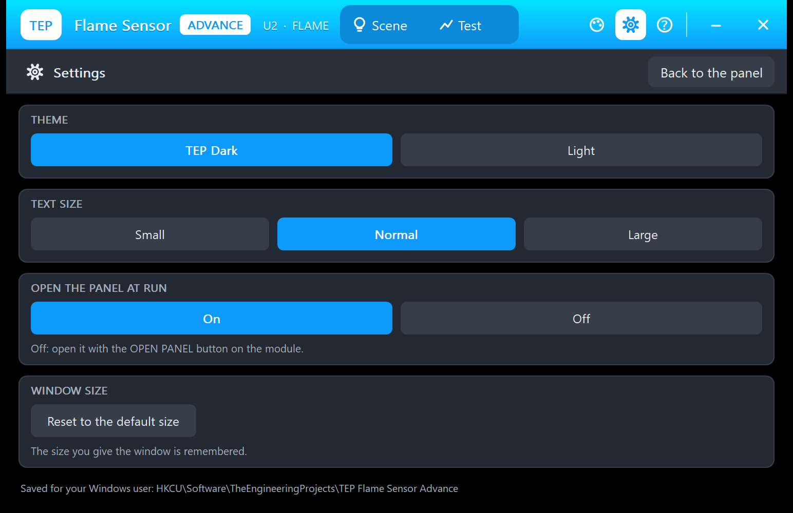
The gear opens Settings: the theme (TEP Dark or Light), the text size (Small, Normal or Large), open the panel at Run (On or Off), and a button that resets the window size.
The ? icon opens Help & Support: eight cards with their links (the flame sensor board of our forum for bugs and ideas, this article, updates, donate, our website and the forum), Check for updates, and Copy diagnostics for a bug report: the sensor, the scene, the D0 log and the test results. A links.ini file next to the DLL can change the links.
Flame Sensor Fire Alarm with Arduino in Proteus
Open Flame-Sensor-ArduinoUnoV3.pdsprj from the Proteus Simulation folder, with Flame_Alarm.hex and both DLLs beside it. Its two Arduino UNOs, from our TEP Arduino UNO V3 library (included in the zip), run the same HEX file:
- NODE 1 - SIMPLE: UNO 1 (ARD1) with the Flame Simple (U1), the alarm LED D1 on A3 and Serial Monitor U3.
- NODE 2 - ADVANCE: UNO 2 (ARD2) with the Flame Advance (U2), the alarm LED D2 on A3 and Serial Monitor U4.
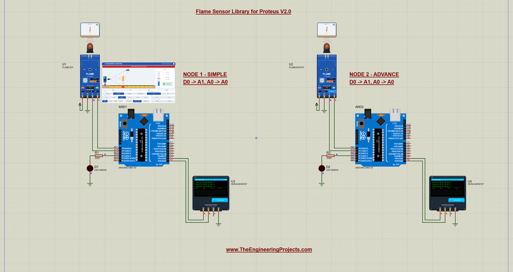
The alarm LEDs blink at 10 Hz while there is a fire, so a screenshot can catch them dark, as here; in the featured image at the top, D1 is lit.
Wiring
| From | To | Why |
|---|---|---|
| Flame sensor VCC / GND | 5 V supply terminal / ground | Power (the PWR LED lights) |
| Flame sensor A0 | Arduino A0 | The analog IR signal, read with analogRead() |
| Flame sensor D0 | Arduino A1, used as a digital input | The comparator output, read with digitalRead() |
| LED (LED-GREEN) + 220 ohm | A3 to ground | The alarm LED; the UNO's own LED on D13 blinks too |
| Serial Monitor RXD / TXD / GND | Arduino D1 / D0 / ground | Shows what the Arduino prints, sends what you type |
| Serial Monitor RXD2 | Not connected | The sensor has no serial line to watch |
A1 works as a normal digital input, and with A0 and A1 both on the UNO's left edge, the two wires never cross. On your own board, D2 or any other digital pin works the same: change SENSOR_D0 in the sketch.
The Arduino Code
The sketch needs no extra library. It starts with the pins:
const int SENSOR_A0 = A0;     // analog output of the sensor board
const int SENSOR_D0 = A1;     // digital output of the sensor board (used as a digital input)
const int ALARM_LED = 13;     // the alarm (the UNO's on-board LED)
const int ALARM_LED2 = A3;    // the demo's green alarm LED (+ 220 ohm to GND)
Then two calibration values say which readings stand for 0 % and 100 % IR level:
const int NO_FLAME_VALUE = 1020;   // analogRead() with no infrared at all  (= 0 % IR level)
const int FULL_IR_VALUE  = 20;     // analogRead() with a flame very close    (= 100 % IR level)
Measure your own module and change them: NO_FLAME_VALUE with no flame in a dark room, FULL_IR_VALUE with a flame right in front of the sensor. In setup(), the sketch opens the serial port at 9600 baud and prints three lines:
  Serial.println("Flame Sensor Fire Alarm - The Engineering Projects");
  Serial.println("Reading A0 and D0 every 0.5 s...");
  Serial.println("TEP Flame Sensor demo v2.0 - type HELP for the commands");
The loop never uses delay(). Every 10 ms it takes a background A0 sample into a ring of 32 (for AVG), and every everyMs (500 ms at the start) it takes a reading:
  if (now - lastSample >= 10) {                    // a background A0 sample every 10 ms (for AVG)
    lastSample = now;
    samples[sampleAt] = analogRead(SENSOR_A0);
    sampleAt = (sampleAt + 1) % 32;
    if (sampleCount < 32) sampleCount++;
  }
  if (everyMs > 0 && now - lastRead >= everyMs) {
    lastRead = now;
    takeReading();
  }
A reading reads A0 and D0. With AVG n, it uses the mean of the last n samples instead of a single one:
  int adc = analogRead(SENSOR_A0);                 // 0..1023, LOW = a lot of infrared (flame)
  if (avgCount > 1 && sampleCount > 1) {           // AVG n: the mean of the last n samples (10 ms apart) instead
    int n = avgCount < sampleCount ? avgCount : sampleCount;
    long sum = 0;
    for (int i = 1; i <= n; i++) sum += samples[(sampleAt + 32 - i) % 32];
    adc = sum / n;
  }
  int d0 = digitalRead(SENSOR_D0);                 // LOW = flame detected
Then the ADC count becomes the IR level in percent. The panels of both devices use the same formula, so the panel and the Serial Monitor agree:
  int irLevel = map(adc, NO_FLAME_VALUE, FULL_IR_VALUE, 0, 100);
  irLevel = constrain(irLevel, 0, 100);
The board's comparator has already decided: D0 LOW means fire. ALARM adc adds an analog alarm level of your own:
  bool fire = (d0 == LOW) || (alarmAdc > 0 && adc < alarmAdc);
  if (fire) Serial.println("FIRE! Flame detected");
  else Serial.println("No flame");
While there is a fire, the alarm LEDs on D13 and A3 blink at 10 Hz, again without delay(), so the sketch keeps answering your commands:
  // blink the alarm LEDs at 10 Hz while there is a fire (no delay(): the commands stay responsive)
  if (alarmOn) {
    if (now - lastBlink >= 50) {
      lastBlink = now;
      blinkOn = !blinkOn;
      setLeds(blinkOn);
    }
  } else if (blinkOn) {
    blinkOn = false;
    setLeds(false);
  }
The commands come in one per line, in upper or lower case. ALARM, for example, takes an ADC value, and 0 switches the analog alarm off:
  } else if (isCommand("ALARM")) {
    long a = number();
    if (a == 0) {
      alarmAdc = 0;
      Serial.println("Analog alarm off - the alarm follows D0 only");
    } else if (a > 0 && a <= 1023) {
      alarmAdc = a;
HELP prints two short lines, so they fit the Serial Monitor's Simple interface:
  if (isCommand("HELP")) {
    Serial.println("Commands: HELP, STATUS, READ, EVERY ms (0 = pause),");
    Serial.println("  ALARM adc (0 = D0 only), AVG n (1 - 32 samples, 10 ms apart)");
To change the sketch, open it in the Arduino IDE, select Arduino Uno, use Sketch > Export Compiled Binary and replace the .hex file in the Proteus Simulation folder with the exported one.
Serial Monitor Commands
| Command | What it does |
|---|---|
| HELP | The command list (two lines) |
| STATUS | The reading interval, AVG, the alarm rule, then the last reading and the alarm (two lines) |
| READ | One reading now |
| EVERY ms | The reading interval, 100 to 10000 ms; EVERY 0 pauses the readings |
| ALARM adc | An analog alarm: FIRE! also when the ADC is below adc; ALARM 0 = D0 only |
| AVG n | Each reading is the mean of the last n A0 samples (1 to 32, taken every 10 ms): smooths the flicker |
How to Run the Demo
- Press Run. Both Serial Monitors (9600 baud) and U2's pop-up open. Both sensors see a candle at 30 cm, the receivers glow and the alarm LEDs blink.
- On U1's panel, click NONE (the flame fades out, "No flame"), then CANDLE (it grows for about a second, then FIRE! again). Try FLICKER OFF, the distances, the angles, SUNLIGHT with NONE, and the pot buttons.
- On U3, click STATUS, AVG 32 and ALARM 600; on U4, STATUS, READ, EVERY 1000 and EVERY 500. Type HELP.
- On U2, run the four tools on the Test tab while the sketch keeps reading: U4 shows how your sketch sees the same changes.
- Close U2's window and open it again with OPEN PANEL; close U1's panel with its red X and open it with PANEL.
Flame Sensor Proteus Simulation Results
The Serial Monitor in Its Simple Interface
The monitor screenshots here show the Simple interface of our TEP Serial Monitor. Only the log, the send box and one slim toolbar row stay visible (baud rate, follow, pause, search and clear), so the window stays small.
- Switch to it: right-click the log and choose Simple interface, or press Ctrl+Shift+U.
- Back to the full view: click the corner button (the expand arrows at the top right), press Esc or Ctrl+Shift+U, or right-click and choose Full interface.
- Your choice is remembered.
Type commands such as STATUS or AVG 32 in the send box and press Enter; the quick buttons come back with the full view. Every line of the demo sketch is shorter than 80 characters, so it fits this small window. Read all about the monitor in TEP Serial Monitor Advance for Proteus.
Start-Up
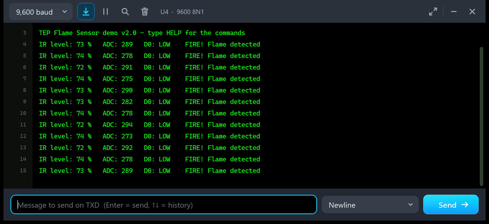
After Run, U4 prints two banner lines ("Flame Sensor Fire Alarm - The Engineering Projects" and "Reading A0 and D0 every 0.5 s..."), the v2.0 line, and then a reading twice a second. In the image, the two banner lines have scrolled up:
TEP Flame Sensor demo v2.0 - type HELP for the commands
IR level: 73 %   ADC: 289   D0: LOW    FIRE! Flame detected
IR level: 74 %   ADC: 278   D0: LOW    FIRE! Flame detected
IR level: 72 %   ADC: 291   D0: LOW    FIRE! Flame detected
IR level: 74 %   ADC: 275   D0: LOW    FIRE! Flame detected
IR level: 73 %   ADC: 290   D0: LOW    FIRE! Flame detected
IR level: 73 %   ADC: 282   D0: LOW    FIRE! Flame detected
IR level: 74 %   ADC: 278   D0: LOW    FIRE! Flame detected
IR level: 72 %   ADC: 294   D0: LOW    FIRE! Flame detected
IR level: 74 %   ADC: 273   D0: LOW    FIRE! Flame detected
IR level: 72 %   ADC: 292   D0: LOW    FIRE! Flame detected
IR level: 74 %   ADC: 278   D0: LOW    FIRE! Flame detected
IR level: 73 %   ADC: 289   D0: LOW    FIRE! Flame detected
The candle flickers, so the ADC moves between 273 and 294 and the IR level between 72 and 74 %, but D0 stays LOW and every line says FIRE!. With FLICKER OFF, the reading is a steady ADC 284.
EVERY 0, HELP, STATUS and READ
IR level: 74 %   ADC: 273   D0: LOW    FIRE! Flame detected
IR level: 72 %   ADC: 292   D0: LOW    FIRE! Flame detected
IR level: 74 %   ADC: 278   D0: LOW    FIRE! Flame detected
EVERY 0
Readings paused - type EVERY 500 to go on
HELP
Commands: HELP, STATUS, READ, EVERY ms (0 = pause),
  ALARM adc (0 = D0 only), AVG n (1 - 32 samples, 10 ms apart)
STATUS
Status: every 0 ms, AVG 1, ALARM on D0 LOW only
  last: IR 74 %, ADC 278, D0 LOW, alarm ON after 331 readings
READ
IR level: 73 %   ADC: 289   D0: LOW    FIRE! Flame detected
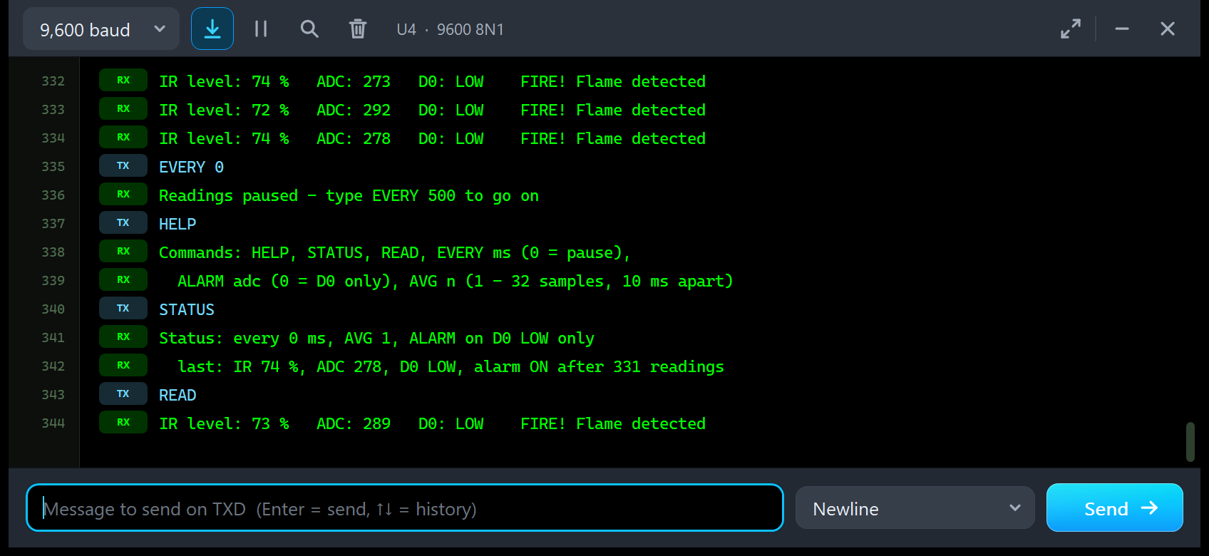
EVERY 0 pauses the readings, so the log stays still. STATUS gives the interval (0 ms = paused), AVG and the alarm rule, then the last reading. READ takes one reading on demand. Once you send a command, the log marks your lines TX and the sketch's lines RX.
AVG 32 and ALARM 600
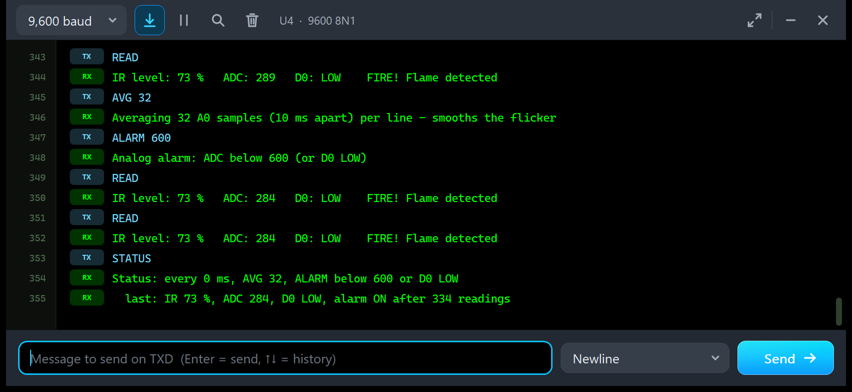
READ
IR level: 73 %   ADC: 289   D0: LOW    FIRE! Flame detected
AVG 32
Averaging 32 A0 samples (10 ms apart) per line - smooths the flicker
ALARM 600
Analog alarm: ADC below 600 (or D0 LOW)
READ
IR level: 73 %   ADC: 284   D0: LOW    FIRE! Flame detected
READ
IR level: 73 %   ADC: 284   D0: LOW    FIRE! Flame detected
STATUS
Status: every 0 ms, AVG 32, ALARM below 600 or D0 LOW
  last: IR 73 %, ADC 284, D0 LOW, alarm ON after 334 readings
AVG 32 makes each reading the mean of the last 32 A0 samples, taken 10 ms apart. The two READs after it both say ADC 284: the flicker is averaged away, and 284 is the candle's steady value. ALARM 600 adds an analog alarm: FIRE! also when the ADC is below 600, even while D0 is HIGH. Try it with the candle at 50 cm and the pot at 60 % (click - LESS twice): D0 stays HIGH, but the ADC (about 516) is below 600, so the sketch still says FIRE!.
Troubleshooting
- D0 stays HIGH with a flame: the flame is too far, turned away (60 degrees or more), or the pot is not sensitive enough; the window and the banner tell you which. A candle you have just lit needs about half a second.
- D0 is LOW with no flame: sunlight (raise the trip level with - LESS, see the Sunlight test), or a very sensitive pot.
- D0 flickers between LOW and HIGH: a flickering flame right at the trip level. Move the flame or the pot, or debounce D0 in your sketch.
- The ADC jumps by 20 to 40 counts: the flame's flicker. Use FLICKER OFF, or AVG n in the sketch.
- The panel's ADC and the sketch's differ by a count or two: the panel refreshes every 40 ms, the sketch reads at its own moment.
- The Test tab says "Cannot start: ...": the reason is in the message (no power, or another test is running).
- The part is not simulated, or there is no panel: TEPFLAME.DLL is missing from MODELS and from the project folder. No monitor window: TEPSERIALMON.DLL is missing, or click OPEN MONITOR on the monitor part.
- The Advance pop-up does not appear: click OPEN PANEL on the board, or turn "Open the panel at Run" back on in Settings.
- Your own sketch waits for D0 with a pin-change interrupt: the ATmega328P of Proteus 8.5 does not run pin-change interrupts. Use
digitalRead(), as the demo does, orattachInterrupt()on D2 (INT0).
Found a bug? Please post it in the flame sensor board of our forum with a screenshot, the Serial Monitor text, the simulation log and, for the Advance, the Copy diagnostics text.
Things to Know Before Using a Real Flame Sensor Module
The demo sketch uses only analogRead(), digitalRead() and Serial, so it runs on a real UNO with a real flame sensor module too. Keep in mind:
- Supply: 3.3 to 5 V. A0 and the pot's reference follow VCC (they are ratiometric).
- Polarity: D0 goes LOW on a flame on almost every board, but a few clones invert it: check the D0 LED. A0 is LOWER with more infrared; a few tutorials say the opposite, so check yours with a lighter.
- Range: a lighter is seen at about 80 cm and a bigger flame further away; the pot sets it. A candle's range in our model is 50 cm at the middle pot setting (sources quote 50 to 100 cm).
- False alarms: sunlight, halogen or incandescent lamps, IR heaters and TV remotes can trigger the module; LED and fluorescent room light hardly do. Test your fire alarm away from the window.
- No hysteresis: debounce D0 or average A0 before you sound an alarm.
- Calibration: measure your own module and set NO_FLAME_VALUE and FULL_IR_VALUE. The simulated AVR of Proteus rounds A0 to the nearest count; a real ATmega328P truncates, so it can read one count lower.
- Safety: this is a hobby module, not a certified fire detector. Never use it as the only fire protection.
Limitations of the Simulation
- Not modelled: the receiver's spectrum and temperature, two flames at once, reflections, the LM393's own delays (microseconds), and the 3-pin and 5-channel versions of the module.
- Model values: the flames' powers, the ambient light levels, the ignition times and the flicker tones are our model's choices, based on the module's published descriptions, not on a data sheet. The Sunlight test's flicker frequency is an estimate from mean crossings (about 3 Hz for tones of 3.1, 7.3 and 12.7 Hz).
- The model is our own implementation. The HEX file also contains the Arduino AVR core 1.8.6, which includes LGPL-licensed code; its source code is on GitHub.
- Tested in Proteus 8.5 in October 2026 (the demo, both panels, the four tools, Settings and Help) and with 1,825 automatic PC checks, all passed, 24 of them with the real demo sketch on two simulated UNOs. Proteus 7 is not supported.
Building a complete fire alarm? Add our Gas Sensor Library for Proteus V2.0 (MQ-2) for gas detection, and our SIM800L Library for Proteus to send an SMS when the flame sensor trips. Looking for obstacles instead of flames? Try our Infrared Sensor Library for Proteus V2.0 (FC-51), another LM393 infrared board.
So, that was all about the Flame Sensor Library for Proteus V2.0. I hope the live scene, the "what the sensor sees" window, the sunlight false alarm and the four test tools make the flame sensor much easier to understand, so your fire alarm works the first time you wire a real module. If you use the Flame Sensor Library for Proteus in a project, please share your feedback in the comments or in our forum, and if you have any questions, ask in the comments and I will help you out. Till the next tutorial, take care and have fun!