Hello friends, I hope you all are doing great. Today, I am going to share the ESP32 RS485 Modbus Power Monitor with PZEM-017 (Proteus Simulation), the thirty-ninth project of our IoT Projects series. If you have searched for a Proteus simulation of an ESP32 talking Modbus RTU over RS485, here is a complete one. An ESP32 DevKit V1 is the Modbus master of an RS485 bus with two PZEM-017 DC energy meters on the same pair of wires, one on each circuit of a 12 V supply: a fridge and the lights. It reads the voltage, current, power and energy of both circuits every second, trips the lights circuit like an electronic circuit breaker when it is overloaded, and serves a live web dashboard on a laptop or a phone.
Camper vans, boats, workshops and solar sheds all live on 12 V, and the questions are always the same: where is the power going, and what happens when someone plugs in too much? Industrial meters answer the first over RS485 and Modbus, a protocol that has connected meters, drives and sensors for decades because it is simple, robust over long cables, and lets dozens of devices share two wires. In this tutorial, we will go through the circuit, learn how RS485 sends data on a differential pair, take a Modbus RTU frame apart byte by byte, see how two meters share the bus by their addresses, decode the PZEM-017's registers, build an electronic breaker that tells an overload from a lamp's switch-on surge, walk through the Arduino sketch, and then run the simulation: both meters on the bus, a second lamp plugged in, the breaker tripping, a re-arm too early and a re-arm that holds. At the end, you can download the project with the sketch and every library file.
NOTICE: Our team has put a lot of effort into this project: the circuit, the code and every part in the simulation are our own work, and you get them all free. Your feedback is the fuel that keeps us going, so please tell us what you think in the comments below. And if our free projects help you, you can buy us a coffee. So, let's get started with the ESP32 RS485 Modbus Power Monitor with PZEM-017 (Proteus Simulation):
What Does This RS485 Power Monitor Do?
- Two meters on one bus: two PZEM-017s at Modbus addresses 1 and 2 share the same A / B pair.
- Circuit by circuit: the voltage, current, power and energy of the fridge and of the lights, every second.
- A hand-written Modbus master: every frame is built byte by byte, with its CRC, so you can see exactly what goes on the wire.
- An electronic circuit breaker: the lights circuit trips above 3.0 A in two readings in a row, through a MOSFET.
- Surge-proof: a cold lamp's switch-on surge lasts milliseconds and never trips it; an overload does.
- A dashboard: RE-ARM, OFF and RESET of the energy counters, the supply, both circuits and the events, on a laptop or a phone.
It is a great project for learning RS485 and Modbus RTU, which you will meet in solar inverters, energy meters, VFDs and PLCs, and for learning how smart breakers protect a circuit. In the simulation, the MAX485's pop-up decodes every frame on the bus, the PZEM-017s' pop-ups show their circuits and registers, the bulbs glow at their filaments' temperature, and a toggle switch plugs in the second lamp.
Components Used in the Proteus Simulation
All the parts come from our Proteus libraries, each with its own tutorial. The project zip at the end includes every LIB and DLL file.
| Part | Proteus device | Library post | Connection |
|---|---|---|---|
| ESP32 DevKit V1 | ESP32 DEVKIT V1 | ESP32 DevKit V1 Library for Proteus | U1, TEP-WiFi 192.168.1.101 |
| MAX485 RS-485 module | MAX485ADVTEP | MAX485 RS-485 Module Library for Proteus | U2, RX2 / TX2 / D4 |
| PZEM-017 DC energy meter x 2 | PZEM017TEP | PZEM-017 DC Energy Meter Library for Proteus | EM1 address 1, EM2 address 2 |
| P21W 12 V 21 W bulb x 2 | BULBP21WTEP | Filament Bulb Library for Proteus | L1, L2: the lights |
| Toggle switch | SWITCHTOGGLETEP | Toggle Switch Library for Proteus | SW1, the second lamp |
| IRLZ44N MOSFET | IRLZ44NTEP | N-MOSFET Library for Proteus | Q1, gate D25 |
| Resistors 100, 10k | RESISTOR4BANDTEP | Resistor Library | R3, R4 (the gate) |
| Laptop WiFi Monitor | LAPTOP WIFI MONITOR | Laptop WiFi Monitor | PC1 |
| Mobile WiFi Monitor | MOBILE WIFI MONITOR | Mobile WiFi Monitor | MOB1 |
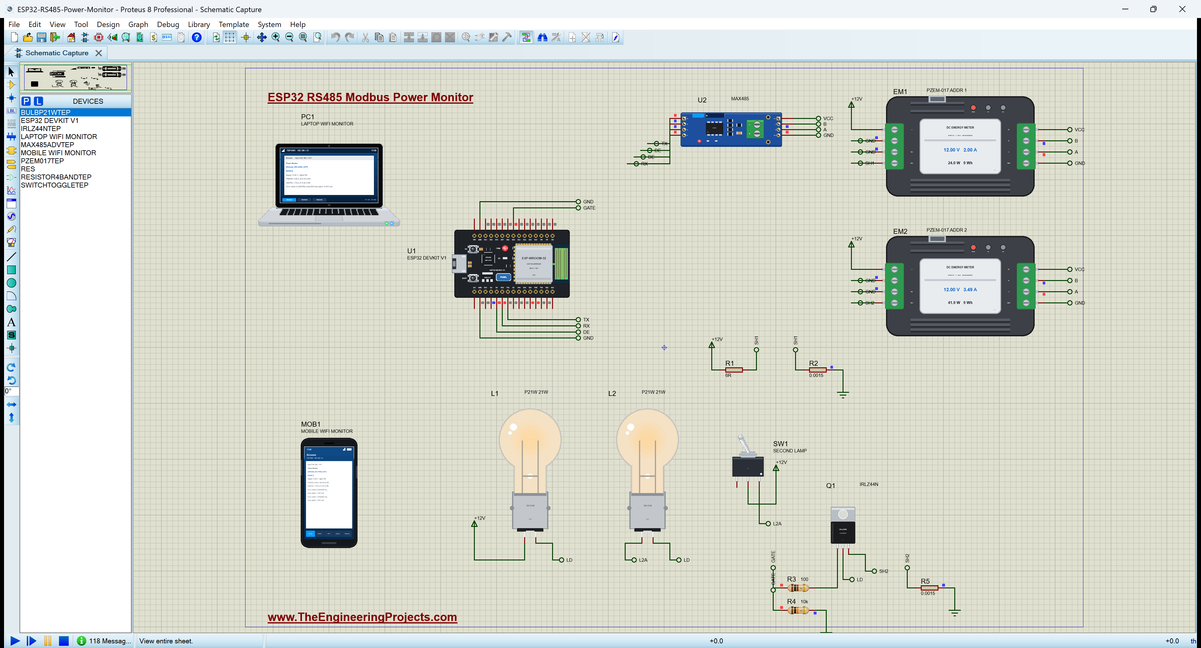
The 12 V supply is a set of Proteus +12V terminals, which stand for a battery or a power supply. The fridge load (R1, 6 ohm) and the two 50 A / 75 mV shunts (R2 and R5, 0.0015 ohm) are Proteus's own resistors. The MAX485, the PZEM-017s, the bulbs, the switch and the MOSFET are our models with pop-ups.
Proteus Simulation of the Power Monitor: the Circuit
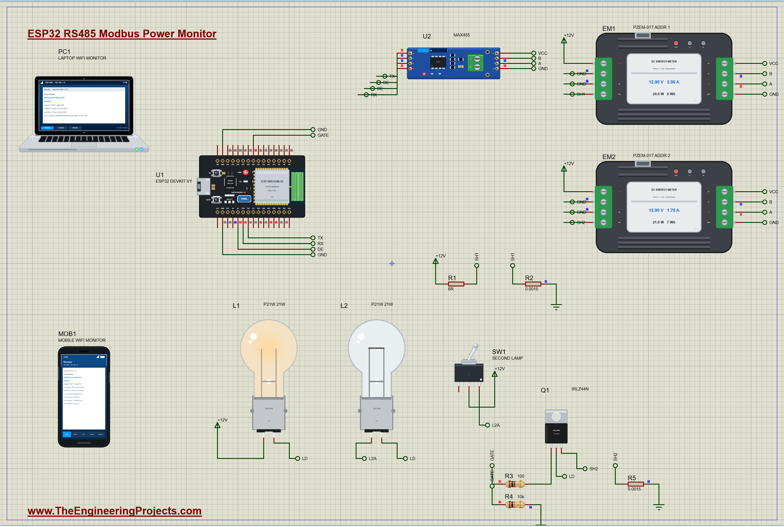
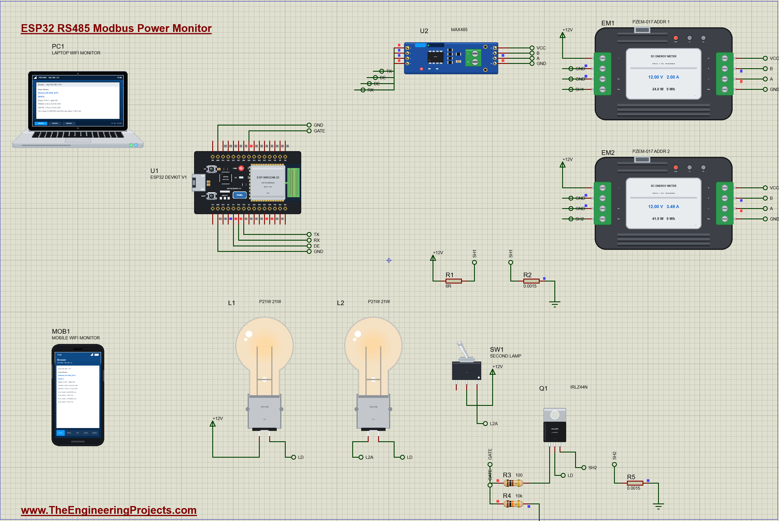
| Part | Pins | ESP32 / other |
|---|---|---|
| U2 MAX485 | RO / DI / DE + RE | RX2 (GPIO16) / TX2 (GPIO17) / D4 |
| U2 MAX485 | VCC / A / B / GND | 5 V / the bus A / the bus B / GND |
| EM1, EM2 | 5V / A / B / GND | 5 V / the bus A / the bus B / GND |
| EM1 | V+ / V-, SH- / SH+ | +12 V / GND / the fridge's side of R2 |
| EM2 | V+ / V-, SH- / SH+ | +12 V / GND / Q1's source, the lights' side of R5 |
| Q1 IRLZ44N | G / D / S | D25 through R3 100 ohm, R4 10k to GND / both bulbs / SH2 |
| The circuits | +12 V - R1 6 ohm - R2 - GND; +12 V - L1 (and L2 through SW1) - Q1 - R5 - GND |
Each circuit has its own shunt in its negative lead, between the load and the supply's minus, and its own meter across that shunt; both meters measure the supply's voltage on V+. On the RS485 side the three devices, the MAX485 and the two meters, hang on the same two wires, A and B, exactly as they would along a cable in a real installation. SW1 is wired on its C and 3 contacts, so the second lamp is out at the start and a click plugs it in.
How the RS485 Modbus Power Monitor Works
RS485: Two Wires, Many Devices
RS485 sends each bit as the difference between two wires, A and B: A above B is a 1, B above A is a 0. Noise picked up along a cable lifts both wires together and leaves the difference untouched, so RS485 works over a thousand metres at moderate speeds. It is half duplex: everyone listens, and only one device drives the pair at a time. The MAX485 is the bridge between the ESP32's UART and the pair. Its DE pin switches the driver on and RE switches the receiver off; tied together on D4, HIGH means talk and LOW means listen. The sketch raises D4, sends the request, waits until the last stop bit has left the UART with Serial2.flush(), and drops D4 before the meter starts its answer.
A Modbus RTU Frame, Byte by Byte
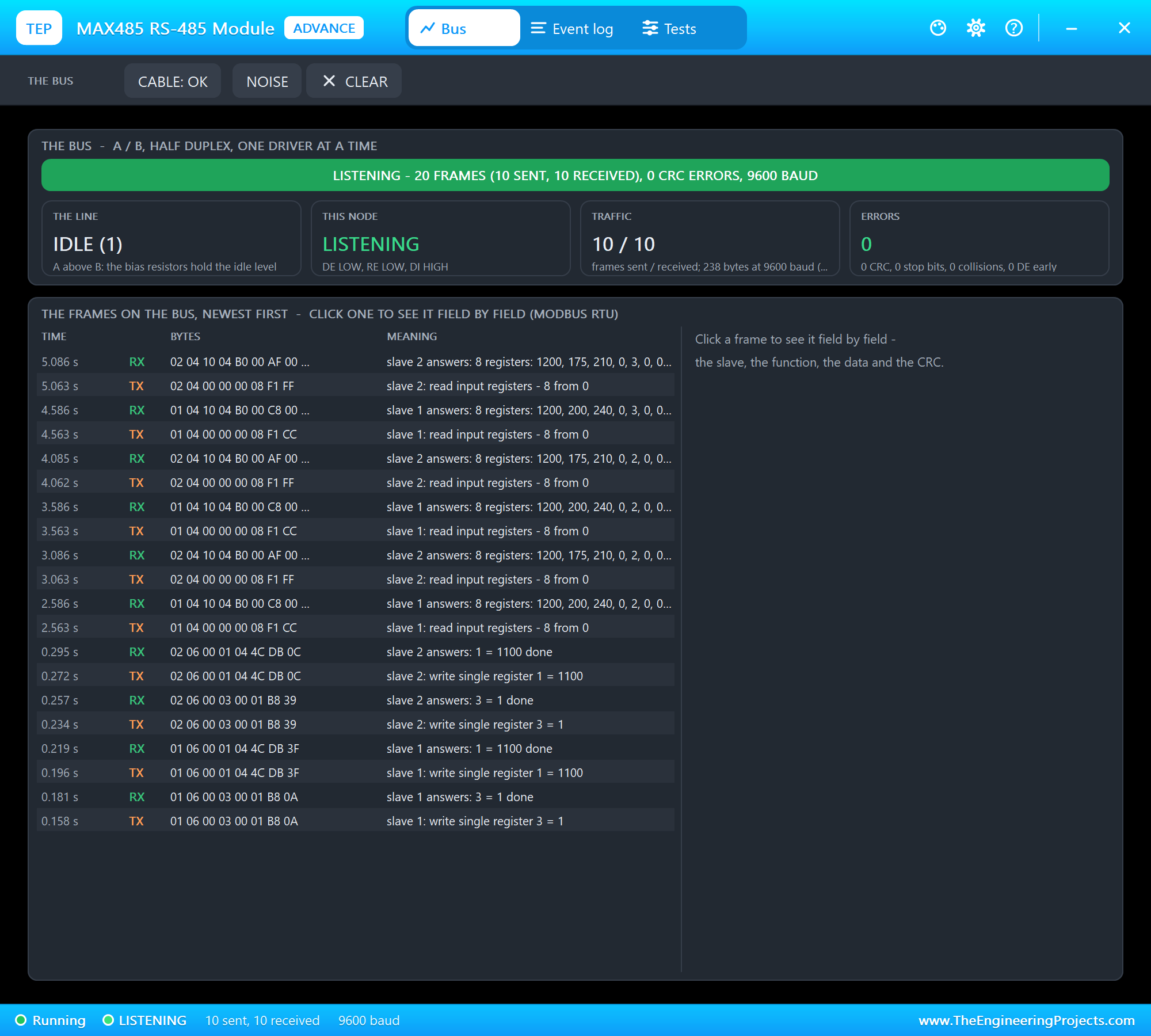
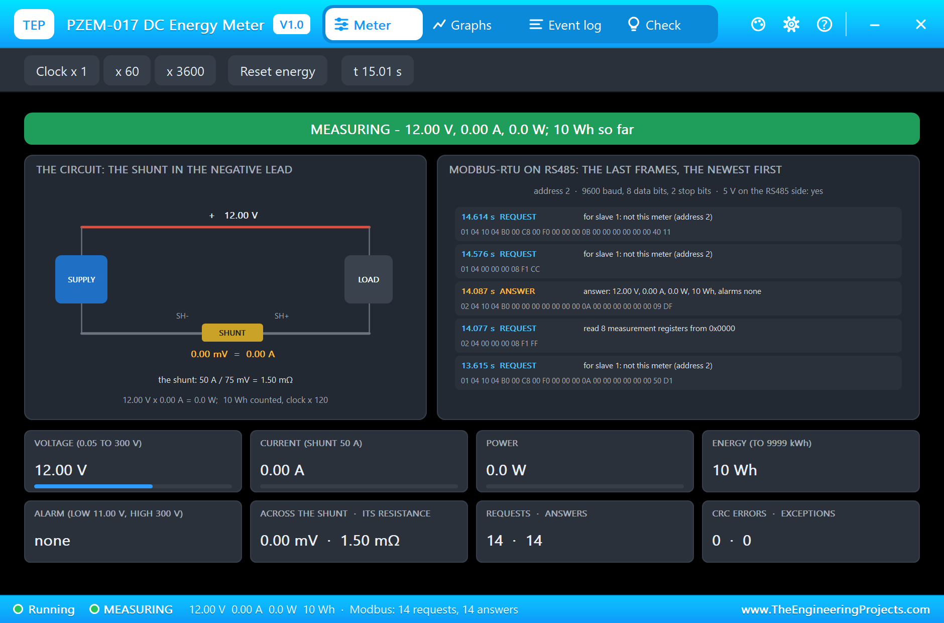
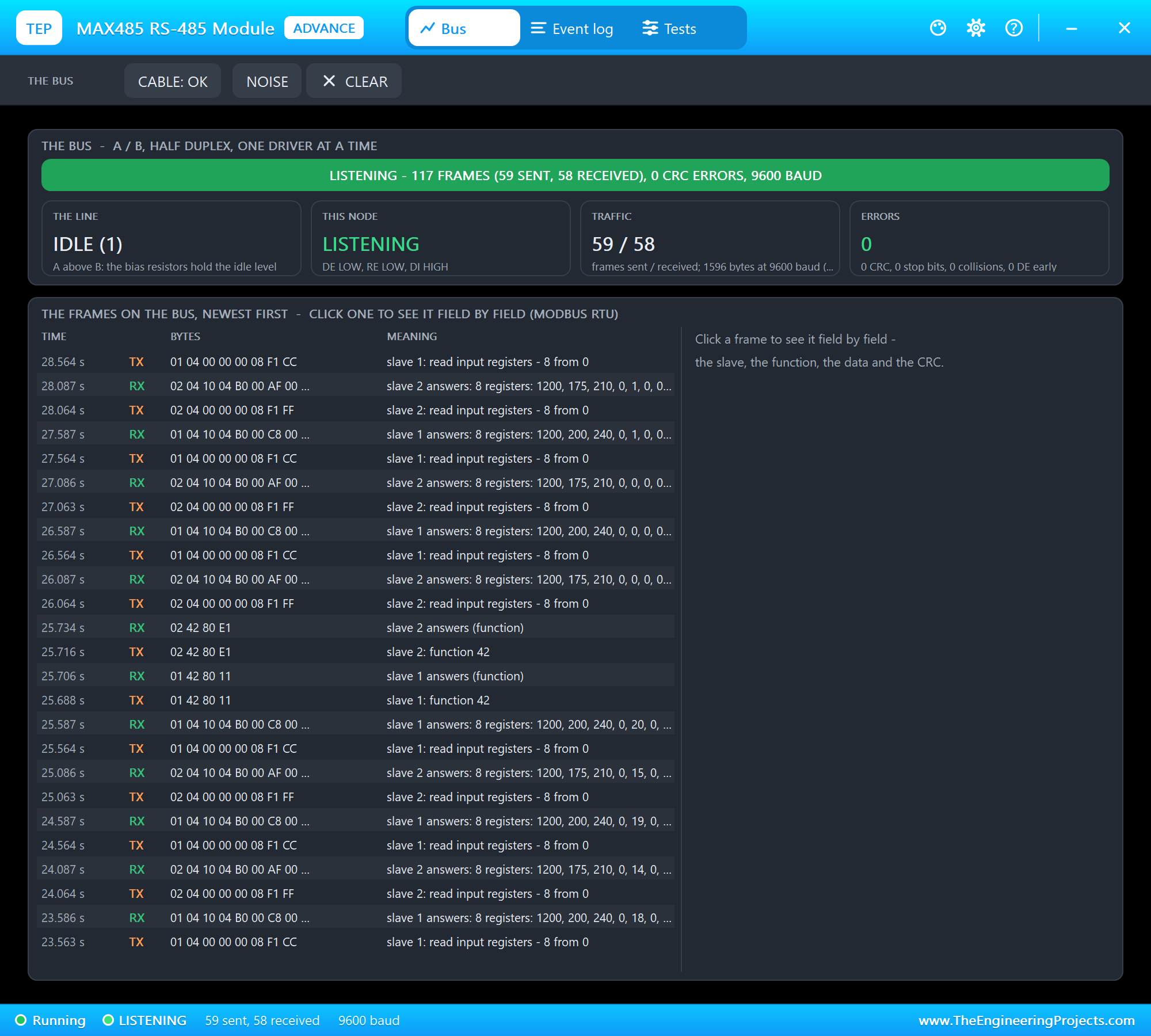
Modbus RTU is a question and an answer. The master sends a frame: the slave's address, a function code, its data, and a 16-bit CRC with the low byte first. Only the slave with that address answers. Worked example: to read meter 1's eight measurement registers the ESP32 sends 01 04 00 00 00 08 F1 CC: address 1, function 4 (read input registers), start at register 0, 8 registers, CRC 0xCCF1. The meter answers with 21 bytes: 01 04, a byte count of 16, sixteen data bytes and its own CRC. Meter 2 gets the same request with 02 at the front and a different CRC, F1 FF. A frame ends with 3.5 characters of silence: at 9600 baud with 8 data bits and 2 stop bits a character is 11 bits, 1.15 ms, so 3.5 characters are 4.0 ms, and the sketch waits 5 ms before every frame.
How busy is the bus? Worked example: a request is 8 bytes, 9.2 ms at 1.15 ms a character; the meter waits 10 ms and answers with 21 bytes, 24 ms; with the 5 ms gap one poll takes about 48 ms. Two meters once a second use under a tenth of the bus's time, so the same pair of wires could serve twenty meters polled once a second, or the two meters could be read ten times faster. On a long cable that spare time is what makes room for retries when a frame is lost to noise.
Reading the PZEM-017's Registers
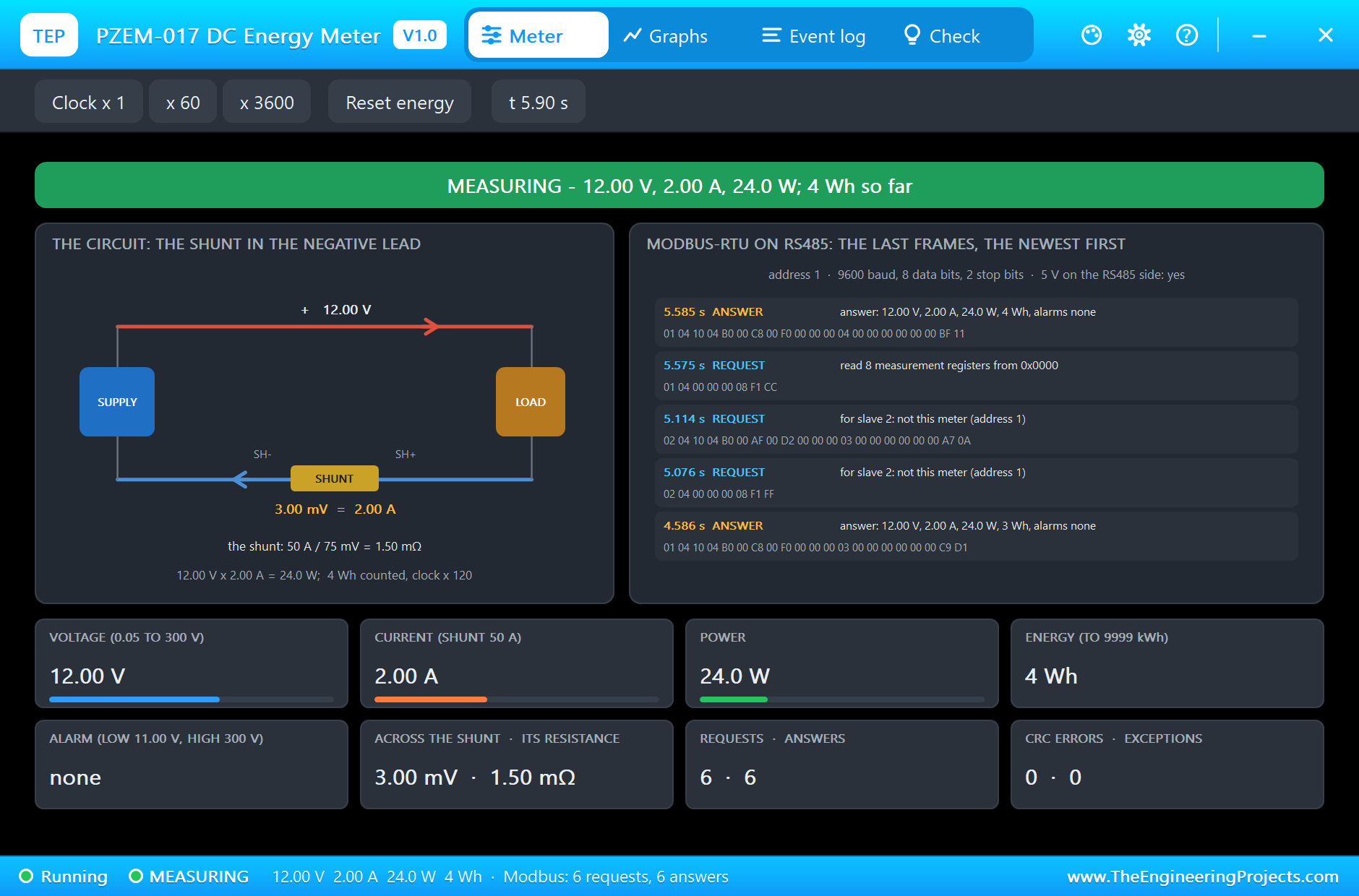
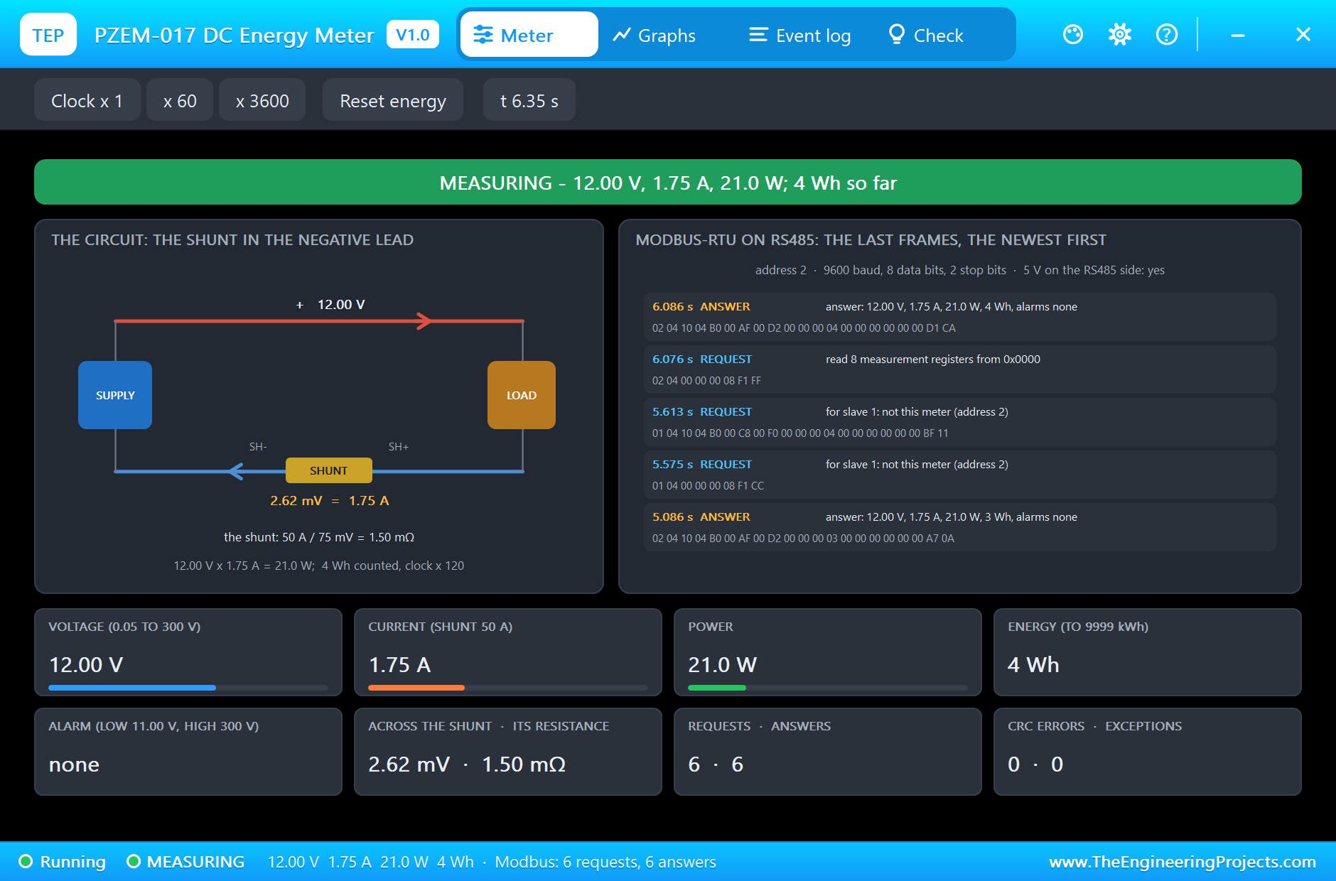
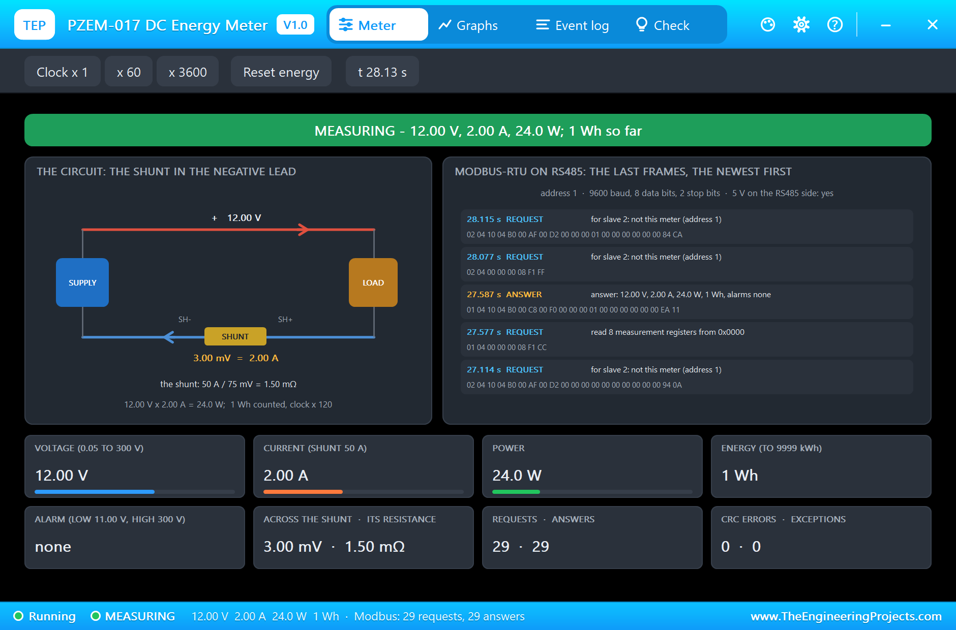
The eight registers are the voltage in 0.01 V, the current in 0.01 A, the power in 0.1 W (two registers, the low word first), the energy in Wh (two registers, the low word first), and the high and low voltage alarms. Worked example: an answer starting 04 B0 00 C8 means 0x04B0 = 1200, 12.00 V, and 0x00C8 = 200, 2.00 A; a power of 240 is 24.0 W. Before reading, the sketch writes two parameters with function 6: register 3 = 1 tells the meter it has a 50 A shunt, and register 1 = 1100 sets its own low-voltage alarm to 11.00 V. The 50 A / 75 mV shunt is 1.5 milliohm: at 2 A it drops only 3 mV, which is why it goes in the negative lead where the meter can measure it against its own ground.
An Electronic Circuit Breaker that Ignores the Surge
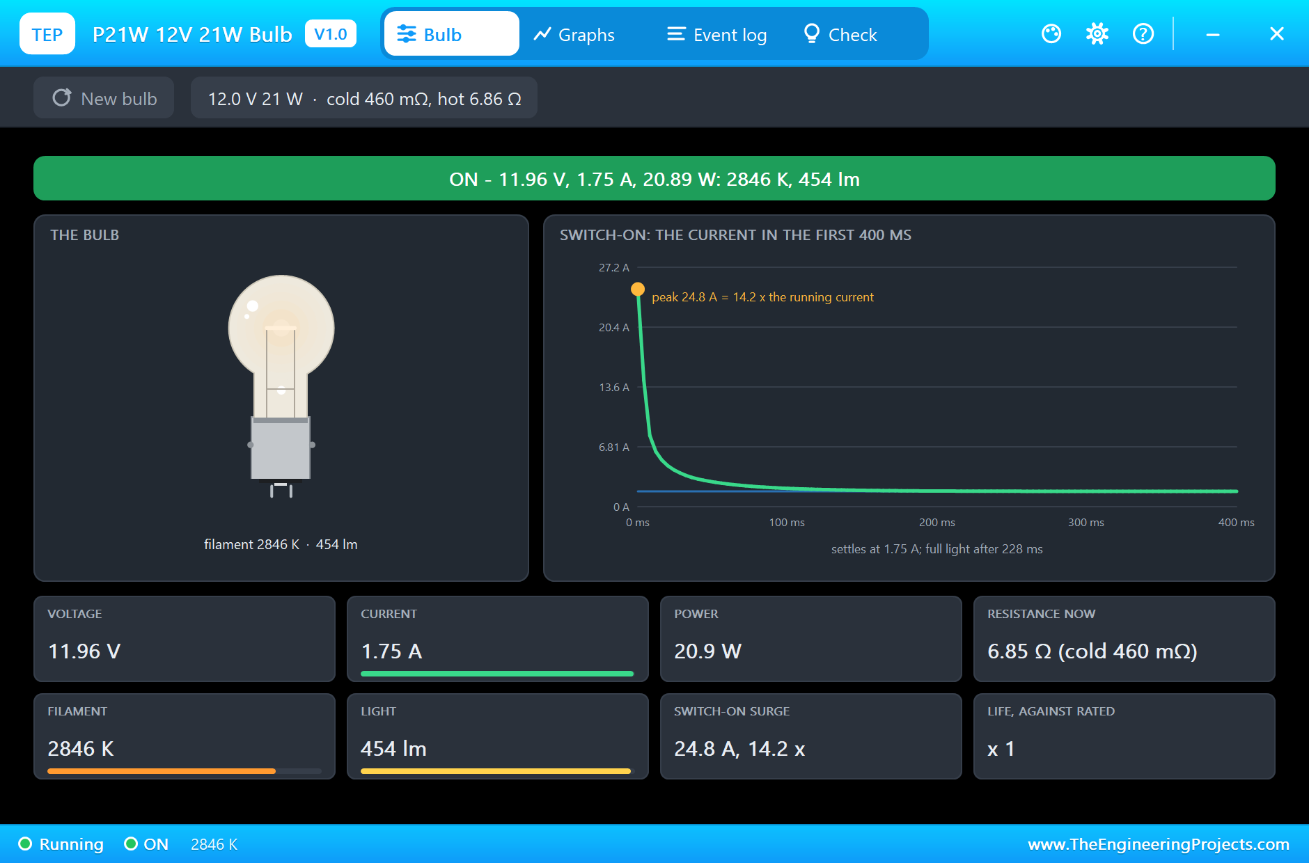
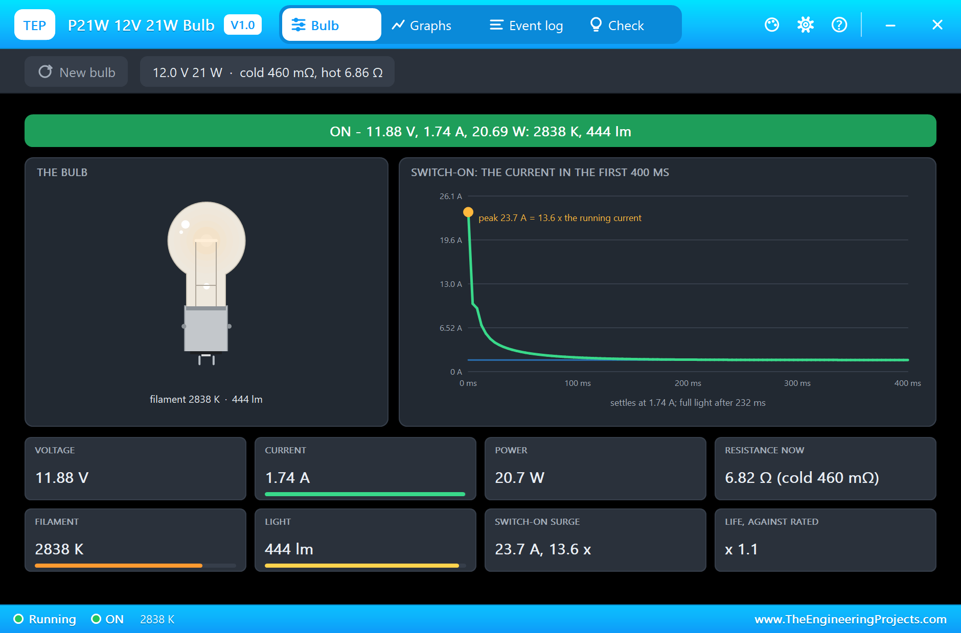
One P21W bulb draws 21 W / 12 V = 1.75 A, so the lights circuit is protected at 3.0 A: one lamp is fine, two lamps, 3.5 A, are an overload. But a filament lamp is a trap for a fast breaker. Cold, its tungsten has about a fourteenth of its hot resistance, so at switch-on a P21W draws 12 to 15 times its current, more than 20 A, for a few milliseconds while the filament heats. A breaker that tripped on one instant reading would trip every time the lights came on. Ours trips only when the current is above 3.0 A in two readings in a row, a second apart: the surge is long gone by the second reading, and an overload is still there. The MOSFET is the switch: D25 HIGH turns it on through the 100 ohm gate resistor, the 10 kohm resistor keeps it off while the ESP32 boots, and with 3.3 V on its gate the IRLZ44N, a logic-level part, conducts the lights' current with a few milliohms.
The Arduino Code Explained
The whole sketch is included in the download. It needs no Modbus library: the frames are built byte by byte on Serial2, so every byte on the bus can be followed in the MAX485's pop-up. At the top is the breaker's limit:
const float TRIP_A = 3.0;                                 // the breaker: the lights circuit's limit
const byte TRIP_READINGS = 2;                             // readings in a row above it (one a second)
Serial2.begin(9600, SERIAL_8N2, 16, 17); // the PZEM-017: 9600 baud, 8 data bits, no parity, 2 stop bitsBuilding and Sending a Frame
for (byte b = 0; b < 8; b++) c = (c & 1) ? (c >> 1) ^ 0xA001 : c >> 1; delay(5); // Modbus: at least 3.5 characters of silence between two frames digitalWrite(DE_RE, HIGH);
Serial2.write(frame, n + 2);
Serial2.flush(); // wait until the last stop bit is out
digitalWrite(DE_RE, LOW);Setting Up and Reading the Meters
const bool s = writeRegister(ADDR[k], 3, SHUNT_50A), l = writeRegister(ADDR[k], 1, LOW_ALARM); frame[0] = ADDR[k]; frame[1] = 0x04; frame[2] = 0; frame[3] = 0; frame[4] = 0; frame[5] = 8; m[k].v = ((unsigned int)frame[3] << 8 | frame[4]) * 0.01; m[k].w = ((unsigned long)frame[9] << 24 | (unsigned long)frame[10] << 16 | (unsigned int)frame[7] << 8 | frame[8]) * 0.1;The Breaker and the Energy Reset
  over = m[1].a > TRIP_A ? over + 1 : 0;
  if (over >= TRIP_READINGS) {
RESET on the dashboard sends each meter function 0x42, which sets its energy counter back to zero:
for (byte k = 0; k < METERS; k++) { frame[0] = ADDR[k]; frame[1] = 0x42; exchange(2, 4); }The pages are / (the dashboard), /arm (re-arm the breaker), /off (the lights off), /reset and /data (JSON). Everything but / and /data goes to one handler, which reads the address: one function serves all the buttons.
How to Run the Proteus Simulation
- Download the project zip below and install the library files (the steps are under the download button).
- Open ESP32-RS485-Power-Monitor.pdsprj from the Proteus Simulation folder. Keep the HEX and the DLL files next to it.
- Press Play. The ESP32 sets up both meters and reads them once a second; the MAX485's pop-up shows every frame.
- Click SW1 to plug in the second lamp: two seconds later the lights circuit trips.
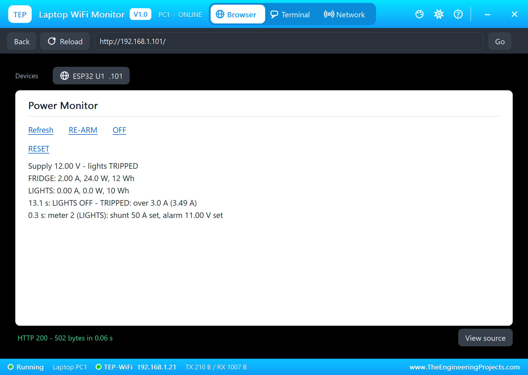
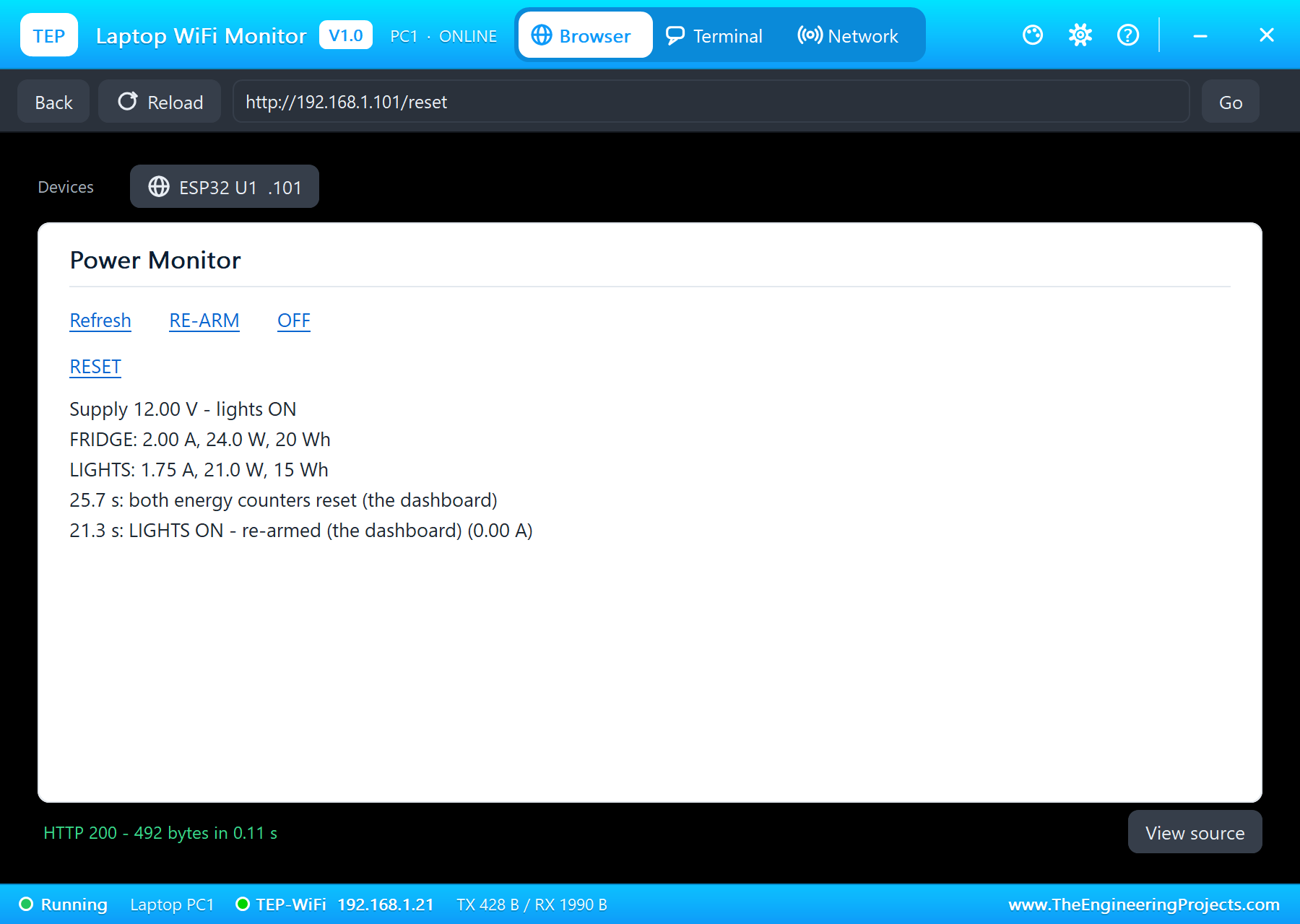
- Open the Laptop WiFi Monitor (PC1) or the Mobile WiFi Monitor (MOB1) and press Go: RE-ARM, OFF and RESET.
Simulation Results: the RS485 Power Monitor in Proteus
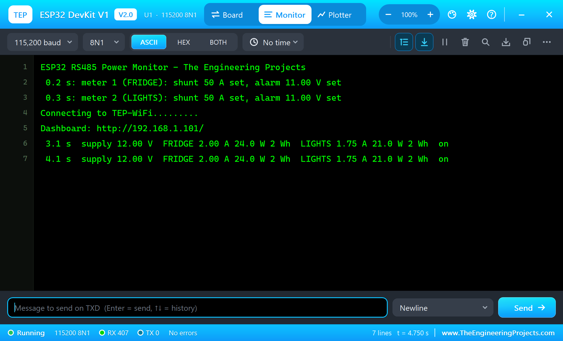
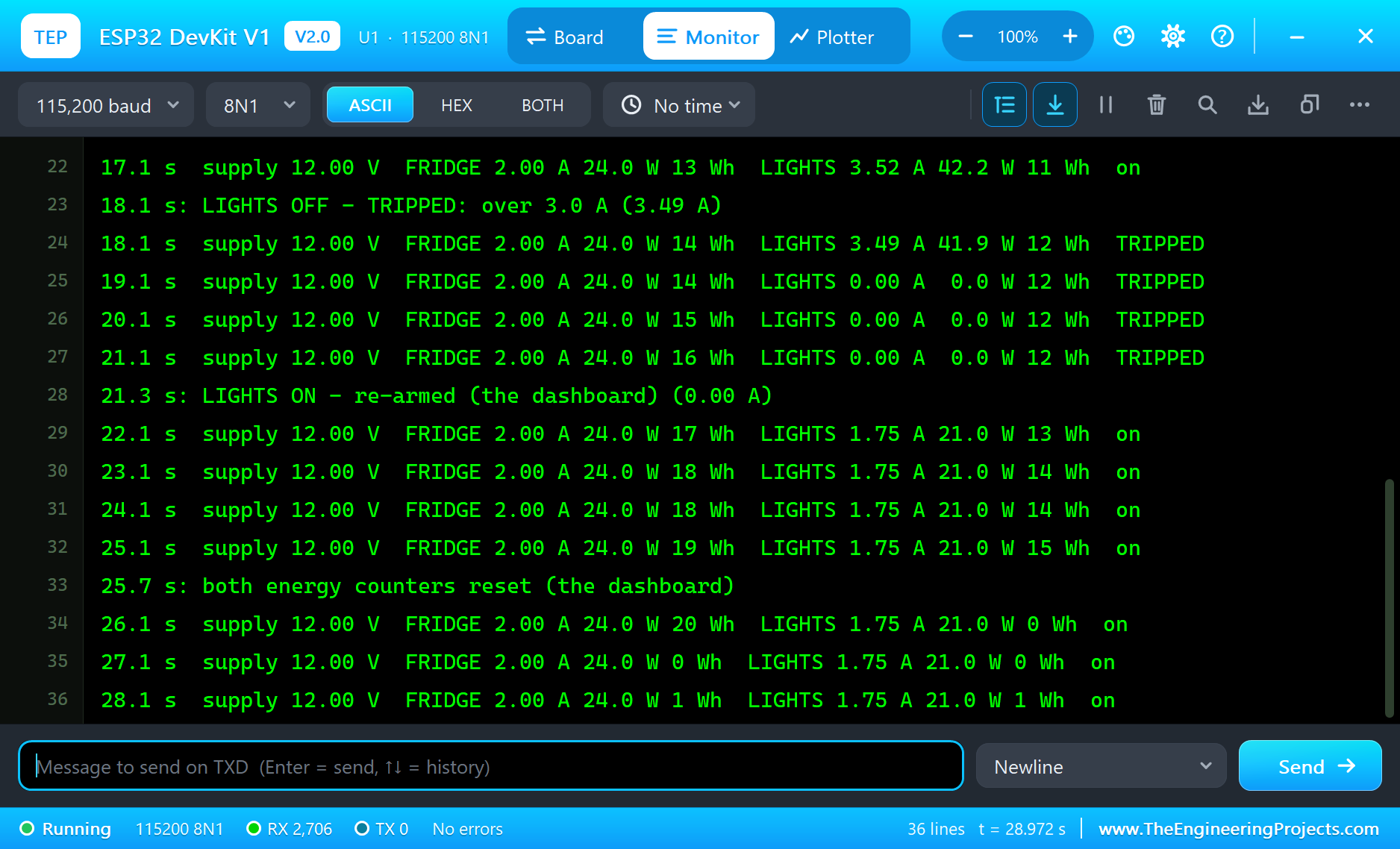
Here is the run that made the screenshots of this tutorial, 29.1 seconds of simulation. The times are the sketch's own, the seconds since the ESP32 started, as it printed them on its serial monitor.
Both Meters on the Bus
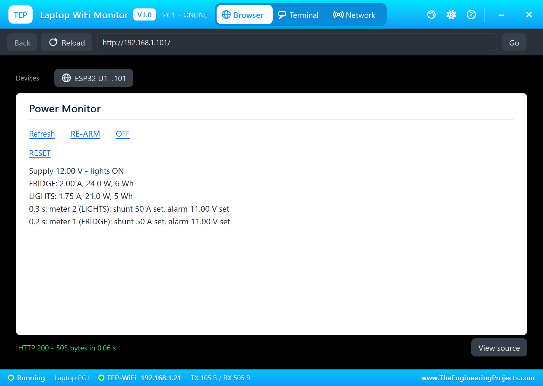
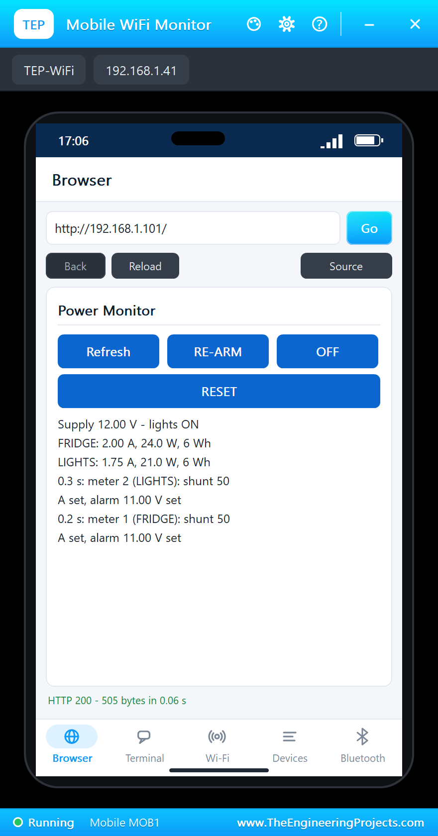
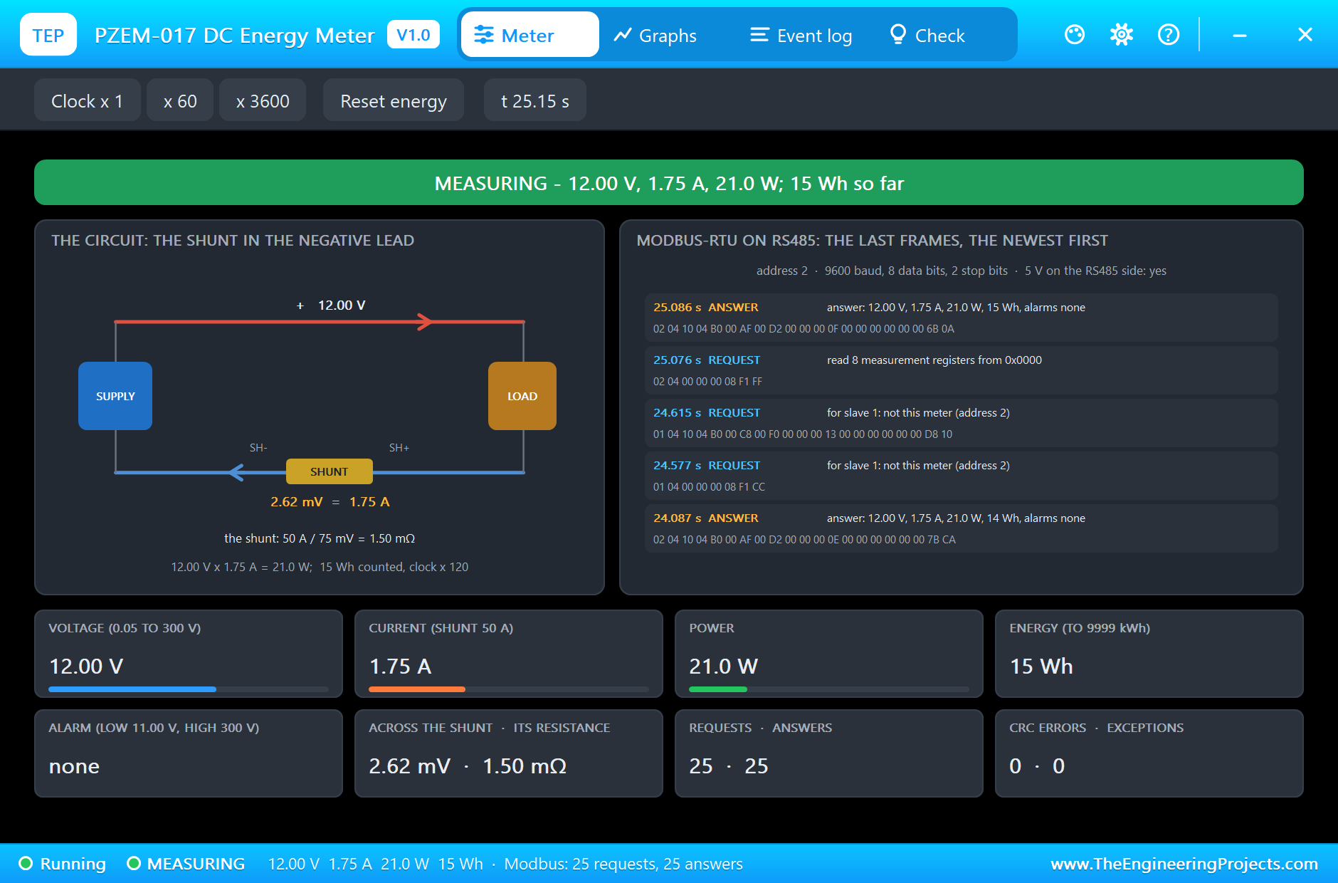
At 0.2 and 0.3 s both meters accept their two parameters: "meter 1 (FRIDGE): shunt 50 A set, alarm 11.00 V set" and the same for meter 2. From then on the ESP32 reads one meter every half second. The supply reads 12.00 V on both, the fridge circuit 2.00 A and 24.0 W, exactly 12 V across 6 ohm, and the lights circuit 1.75 A and 21.0 W, one P21W at its rating. The MAX485's pop-up lists every frame on the pair, the request and the answer, with its meaning decoded, and the watt-hours climb second by second on the meters' fast energy clock.
An Overload, and the Breaker Trips
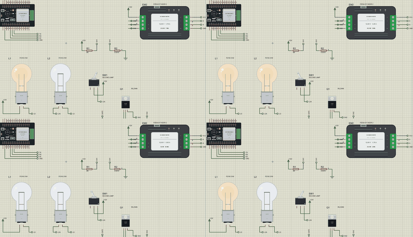
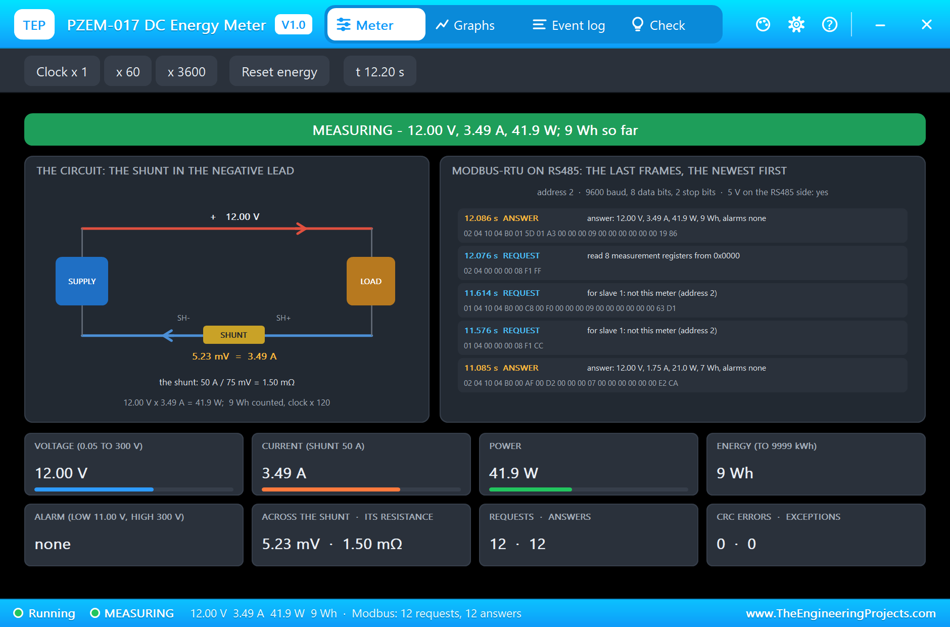
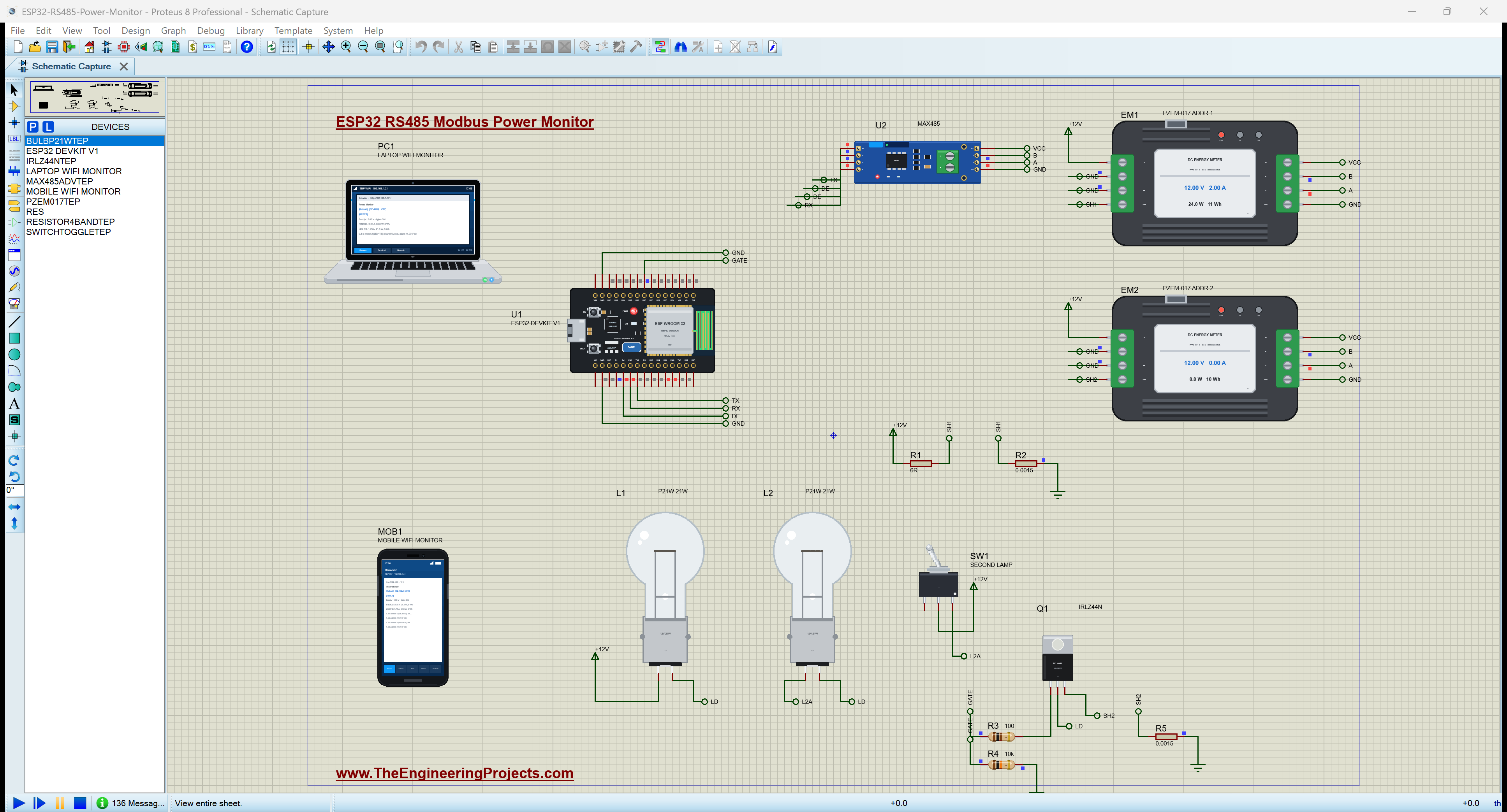
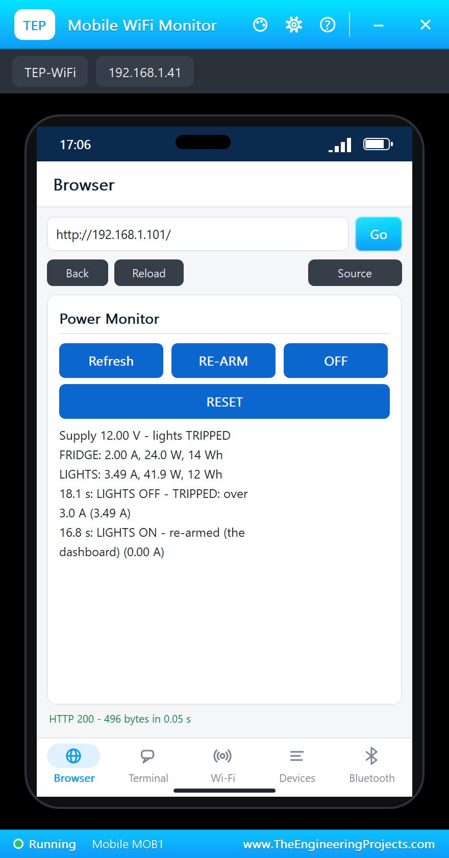
At 11.4 s SW1 plugs in the second lamp. The next reading of the lights circuit, at 12.1 s, is 3.49 A and 41.9 W, over the 3.0 A limit: the first strike. The second, a second later, confirms it: at 13.1 s "LIGHTS OFF - TRIPPED: over 3.0 A (3.49 A)", the MOSFET turns off, both lamps go dark and the lights circuit reads 0.00 A. The fridge circuit never notices: its own meter still reads 2.00 A, because each circuit has its own meter and its own shunt. The second lamp's switch-on surge was over in milliseconds, long before the next reading, and one high reading is never enough anyway.
Re-arming Too Soon, and Re-arming Right
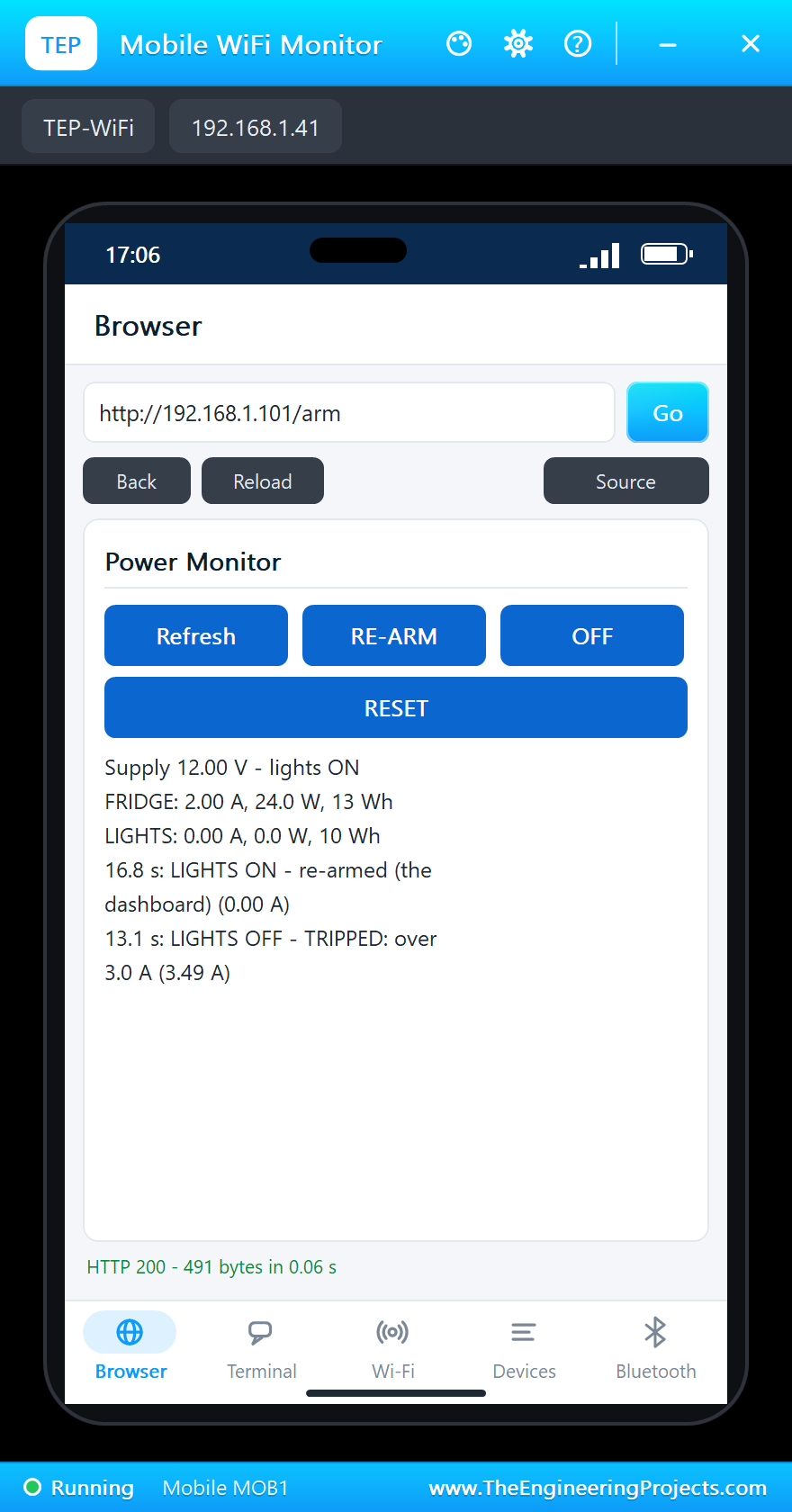
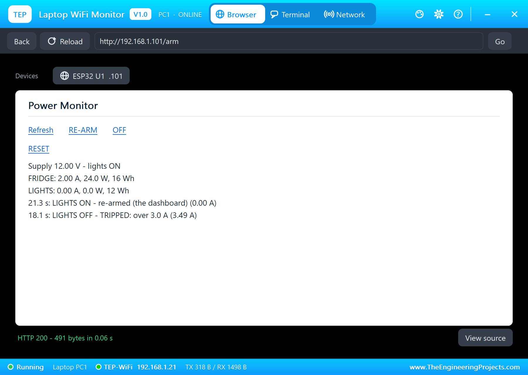
At 16.8 s RE-ARM on the phone switches the lights back on while the second lamp is still plugged in. The breaker does exactly what a real one does: 3.52 A at the next reading, and at 18.1 s "TRIPPED" again. At 19.8 s SW1 unplugs the second lamp, and at 21.3 s RE-ARM on the laptop brings the lights back for good: 1.75 A, reading after reading.
The Energy Reset
At 25.7 s RESET on the laptop sends function 0x42 to both meters: the fridge's 20 Wh and the lights' 15 Wh drop to 0 and start counting again. By the end the MAX485 had seen 118 frames, 59 requests and 59 answers, without a single CRC error.
The Numbers of the Run
| What | Result |
|---|---|
| The supply | 12.00 V on both meters |
| FRIDGE | 2.00 A, 24.0 W |
| LIGHTS | 1.75 A (one lamp), 3.49 A (two lamps) |
| Trips | 13.1 s and 18.1 s, two readings over 3.0 A each |
| RESET | 20 Wh and 15 Wh back to 0 at 25.7 s |
| The bus | 118 frames, 0 CRC errors |
| Simulation | 29.1 s of simulation |
Download the Project Files
Click the button below to download ESP32-RS485-Modbus-Power-Monitor-PZEM-017-Proteus-Simulation-v1.0.zip (about 4.5 MB, without the source code of the models):
ESP32 RS485 Modbus Power Monitor with PZEM-017 (Proteus Simulation) V1.0- Proteus Simulation: ESP32-RS485-Power-Monitor.pdsprj, the HEX file and copies of the models.
- Arduino Code: ESP32_RS485_Power_Monitor.ino, the complete sketch.
- Proteus Library Files: the LIB files of the ESP32, the MAX485, the PZEM-017, the bulb, the toggle switch, the MOSFET, the resistor and the two WiFi Monitors.
- Proteus Model Files: the DLL models.
- README.txt: the installation steps, the properties, the test results and the links to every library post.
No Proteus yet? Read How to Download and Install Proteus 7 and 8. New to libraries? Follow How to Install a New Library in Proteus.
How to Install the Project Files
- Close Proteus and extract the whole zip file, for example to your Desktop.
- Copy the files from Proteus Library Files into the LIBRARY folder of Proteus.
- Copy the files from Proteus Model Files into the MODELS folder.
- Start Proteus and open the project from the Proteus Simulation folder.
Changing the Code
Open ESP32_RS485_Power_Monitor.ino in the Arduino IDE with the ESP32 boards installed, change it, use Sketch > Export Compiled Binary and set U1's PROGRAM property to the new HEX file. The addresses, the limit and the number of readings are at the top; add a third meter by adding its address to ADDR. For our first ESP32 energy project, with a current sensor on mains loads, see the IoT Smart Energy Meter with ESP32.
Ideas to Extend the Project
- Add a breaker to every circuit, each with its own MOSFET and limit.
- Log the energy of each circuit per day and draw a bar chart on the dashboard.
- Add a third PZEM-017 on a solar charger's output and show the energy in and out.
- Re-arm automatically after a cooling time, and lock out after three trips in a row.
- Send an alert to a phone when a circuit trips.
- Use function 0x03 to read back the meters' parameters and show them on the dashboard.
From Simulation to Real Hardware
- Level shifting: the MAX485 is a 5 V part; use a 3.3 V transceiver such as the MAX3485, or a divider on RO, so the ESP32's pins never see 5 V.
- Terminate the bus: put the 120 ohm terminator at the two ends of a long cable and run A and B as a twisted pair.
- Give each meter its own address before you connect them together: two meters at the same address answer at once and garble the bus.
- Keep a real fuse: an electronic breaker reacts in seconds; a fuse close to the supply still protects the wiring from a short.
- Size the MOSFET: the IRLZ44N carries 3.5 A easily; for heavier circuits check its current and its heat at your gate voltage.
Troubleshooting
- A meter does not answer: A and B swapped, two meters with the same address, or no 5 V on its RS485 side.
- Every reply fails its CRC: the frames are sent too close together; keep the 5 ms gap before each request.
- The current reads twice too high: the meter was not told its 50 A shunt in register 3.
- The breaker trips again at once after RE-ARM: the overload is still there; unplug the second lamp first.
Limitations of the Simulation
- The supply is an ideal 12 V source; a real battery sags a little under load, and the meters would show it.
- The meters' energy clock runs 120 times fast (their SPEED property), so the watt-hours climb during a short simulation; a real meter counts in real time.
- In the simulation both sides of the meters share the ground; the real PZEM-017 isolates its RS485 side with optocouplers.
- The network is simulated: the dashboard travels between the ESP32 and the two monitors inside Proteus; the times in this tutorial are simulation time.
- ESP32 is a product of Espressif Systems, the PZEM-017 of Peacefair and the MAX485 of Analog Devices (Maxim) and others. This project is not made or endorsed by them or by Labcenter.
So, that was all about the ESP32 RS485 Modbus Power Monitor with PZEM-017 (Proteus Simulation). I hope it helps you understand the bus that still runs most energy meters, inverters and drives: a differential pair that many devices share, a Modbus frame you can read byte by byte, two meters told apart by their addresses, and an electronic breaker that knows a lamp's surge from a real overload, all tested in a simulation before you connect a single real meter. More IoT projects with the ESP32 and the Raspberry Pi 5 are coming in this series. If you have any questions, ask in the comments and I will help you out. Till the next tutorial, take care and have fun!