Hello friends, I hope you all are doing great. Today, I am going to share the ESP32 4-20 mA Gas Detector with an MQ-4 Sensor - Proteus Simulation, the thirty-seventh project of our IoT Projects series. If you have searched for a Proteus simulation of an ESP32 with a 4-20 mA current loop output, here is a complete one. An ESP32 DevKit V1 reads an MQ-4 methane sensor and sends the gas reading the way industry does, as a current between 4 and 20 milliamperes: an MCP4725 DAC, an LM358 op-amp and a 2N7000 MOSFET turn the reading into the loop current, the ESP32 reads that current back to catch a cut cable, an analog panel meter shows it in the "control room", and a live web dashboard on a laptop or a phone shows the gas in ppm and in percent of the lower explosive limit.
Walk into any factory, boiler house or gas station and the sensors on the walls are not sending numbers over WiFi: they send a current on two wires, 4 mA for nothing and 20 mA for the top of the range. That old, simple signal is still the backbone of industrial measurement, because a current does not care about the length of the cable, noise has a hard time changing it, and a broken wire shows up at once as zero. In this tutorial, we will go through the circuit, learn why the loop starts at 4 mA, measure methane with an MQ-4 and turn its resistance into ppm, build a voltage-to-current converter from a DAC, an op-amp and a MOSFET, read the loop back to find faults, check the loop's voltage budget, walk through the Arduino sketch, and then run the simulation: the warm-up, a loop test, a gas leak with an alarm, fresh air, and a cut cable. At the end, you can download the project with the sketch and every library file.
NOTICE: Our team has put a lot of effort into this project: the circuit, the code and every part in the simulation are our own work, and you get them all free. Your feedback is the fuel that keeps us going, so please tell us what you think in the comments below. And if our free projects help you, you can buy us a coffee. So, let's get started with the ESP32 4-20 mA Gas Detector with an MQ-4 Sensor - Proteus Simulation:
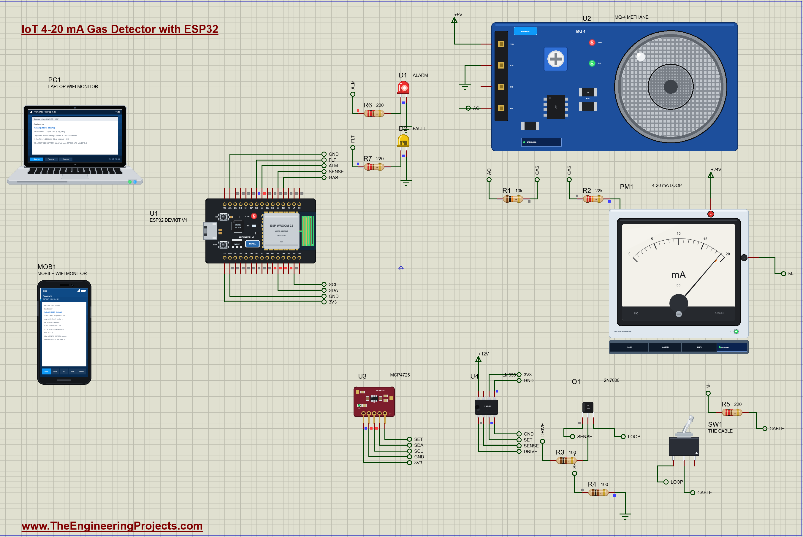
What Does This 4-20 mA Gas Detector Do?
- Measures methane: an MQ-4 sensor reads natural gas from about 200 to 10,000 ppm.
- A real 4-20 mA output: 0 to 10,000 ppm (0 to 20 % of the lower explosive limit) becomes 4 to 20 mA in the loop.
- Fault currents: 3.6 mA while the sensor warms up or when it fails, 20.5 mA above the range, as the NAMUR NE43 recommendation suggests.
- Checks its own loop: the ESP32 measures the current that really flows and reports LOOP OPEN when a cable is cut.
- Gas alarm: a red LED at 10 % of the lower explosive limit, and a yellow FAULT LED for the loop and the sensor.
- Loop test: one click drives 4, 12 and 20 mA, the way an instrument technician checks a loop.
- A dashboard: the gas in ppm and % LEL, the current set and flowing, the state and the events, from a laptop or a phone.
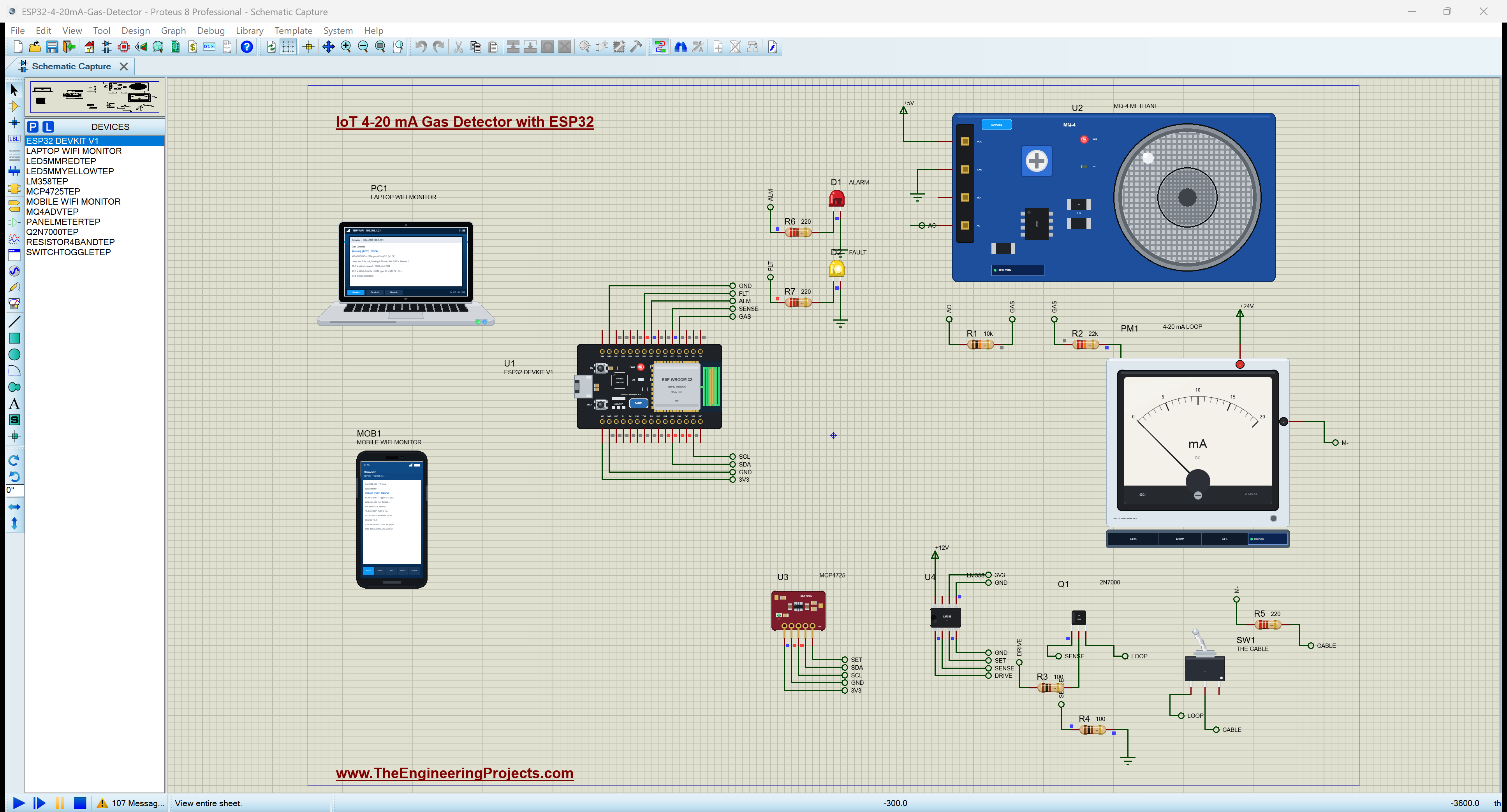
It is a great project for learning how industrial sensors talk to control systems, how a DAC and an op-amp make a precise current, and how a device can supervise its own output. In the simulation, the MQ-4's pop-up sets the gas in the air, the panel meter's needle shows the loop current, and the toggle switch stands for the cable between the field and the control room.
Components Used in the Proteus Simulation
All the parts come from our Proteus libraries, each with its own tutorial. The project zip at the end includes every LIB and DLL file.
| Part | Proteus device | Library post | Connection |
|---|---|---|---|
| ESP32 DevKit V1 | ESP32 DEVKIT V1 | ESP32 DevKit V1 Library for Proteus | U1, TEP-WiFi 192.168.1.101 |
| MQ-4 methane sensor module | MQ4ADVTEP | MQ Gas Sensor Library for Proteus | U2, AO to D34 through a divider |
| MCP4725 12-bit DAC | MCP4725TEP | MCP4725 DAC Module Library for Proteus | U3, I2C at 0x60 |
| LM358 dual op-amp | LM358TEP | LM358 Dual Op-Amp Library for Proteus | U4, on +12 V |
| 2N7000 N-MOSFET | Q2N7000TEP | N-MOSFET Library for Proteus | Q1, in the loop |
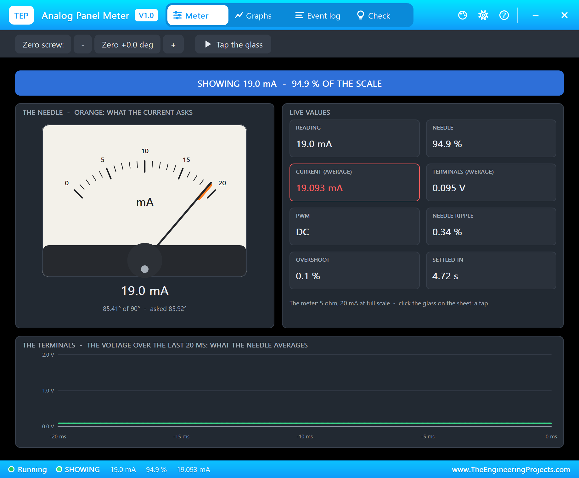
| Analog panel meter, 0 - 20 mA | PANELMETERTEP | Analog Panel Meter Library for Proteus | PM1, the loop indicator |
| Toggle switch | SWITCHTOGGLETEP | Toggle Switch Library for Proteus | SW1, the cable |
| Red and yellow LEDs | LED5MMREDTEP, LED5MMYELLOWTEP | 5mm LED Library | D1 ALARM D25, D2 FAULT D26 |
| Resistors 100, 220, 10k, 22k | RESISTOR4BANDTEP | Resistor Library | R1 - R7 |
| Laptop WiFi Monitor | LAPTOP WIFI MONITOR | Laptop WiFi Monitor | PC1 |
| Mobile WiFi Monitor | MOBILE WIFI MONITOR | Mobile WiFi Monitor | MOB1 |
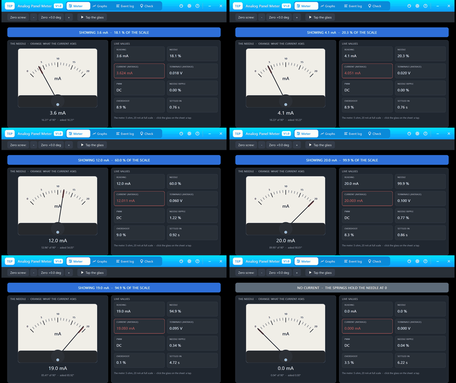
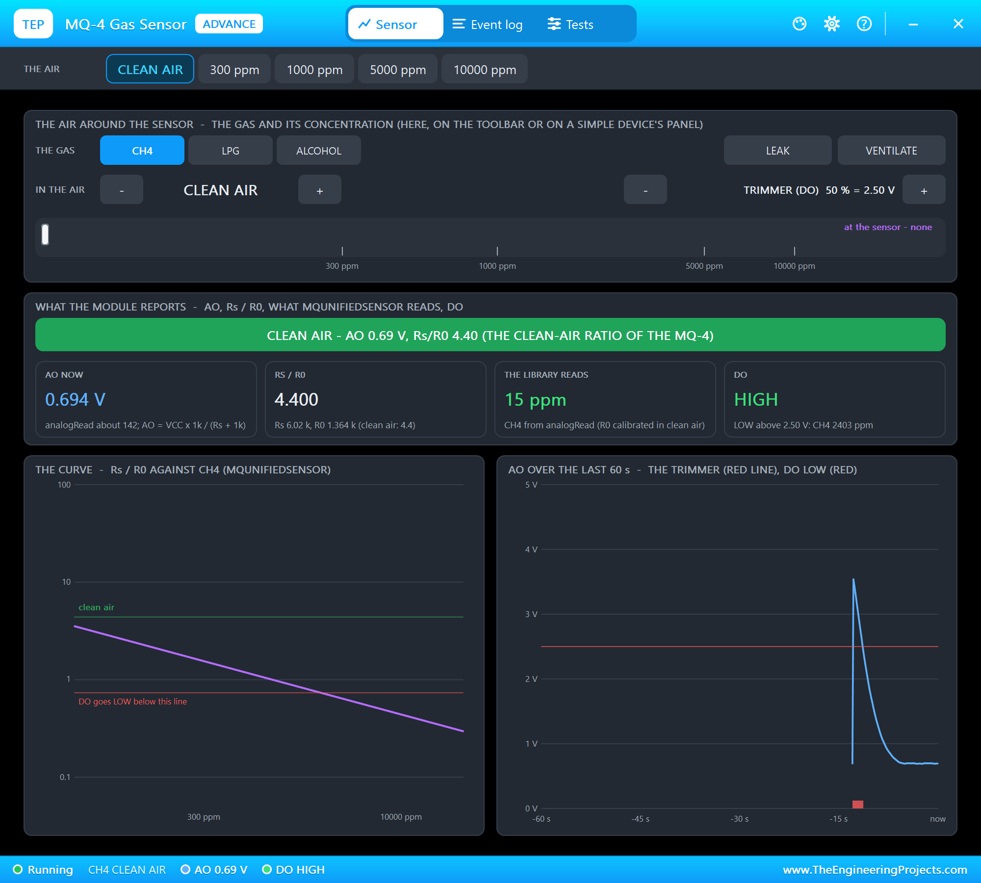
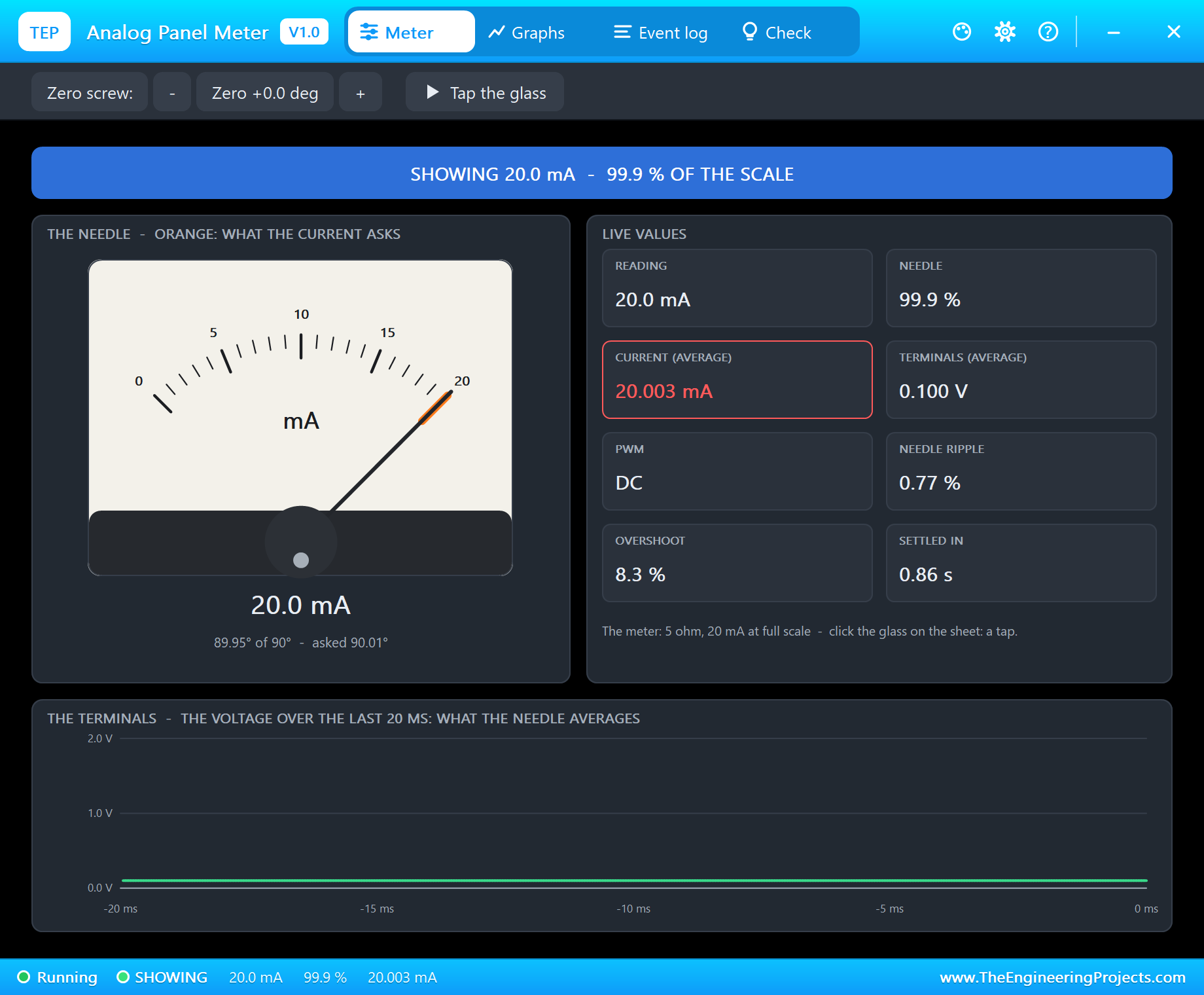
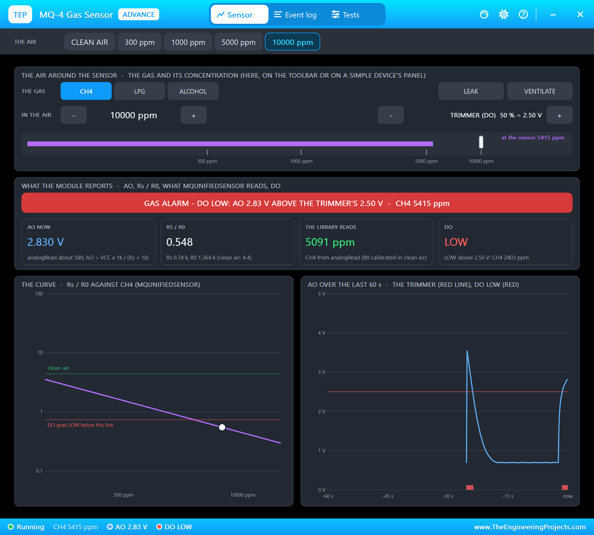
The MQ-4, the MCP4725, the LM358, the 2N7000, the panel meter and the toggle switch are models with pop-ups. The MQ-4's pop-up sets the gas around the sensor with presets, LEAK and VENTILATE, and draws the sensor's curve. The MCP4725's pop-up shows its resistor string, its registers and its EEPROM. The LM358's pop-up shows both amplifiers with their inputs and outputs. The 2N7000's pop-up shows its region, its current and its power. The panel meter's pop-up shows the needle, the current and how the needle settles.
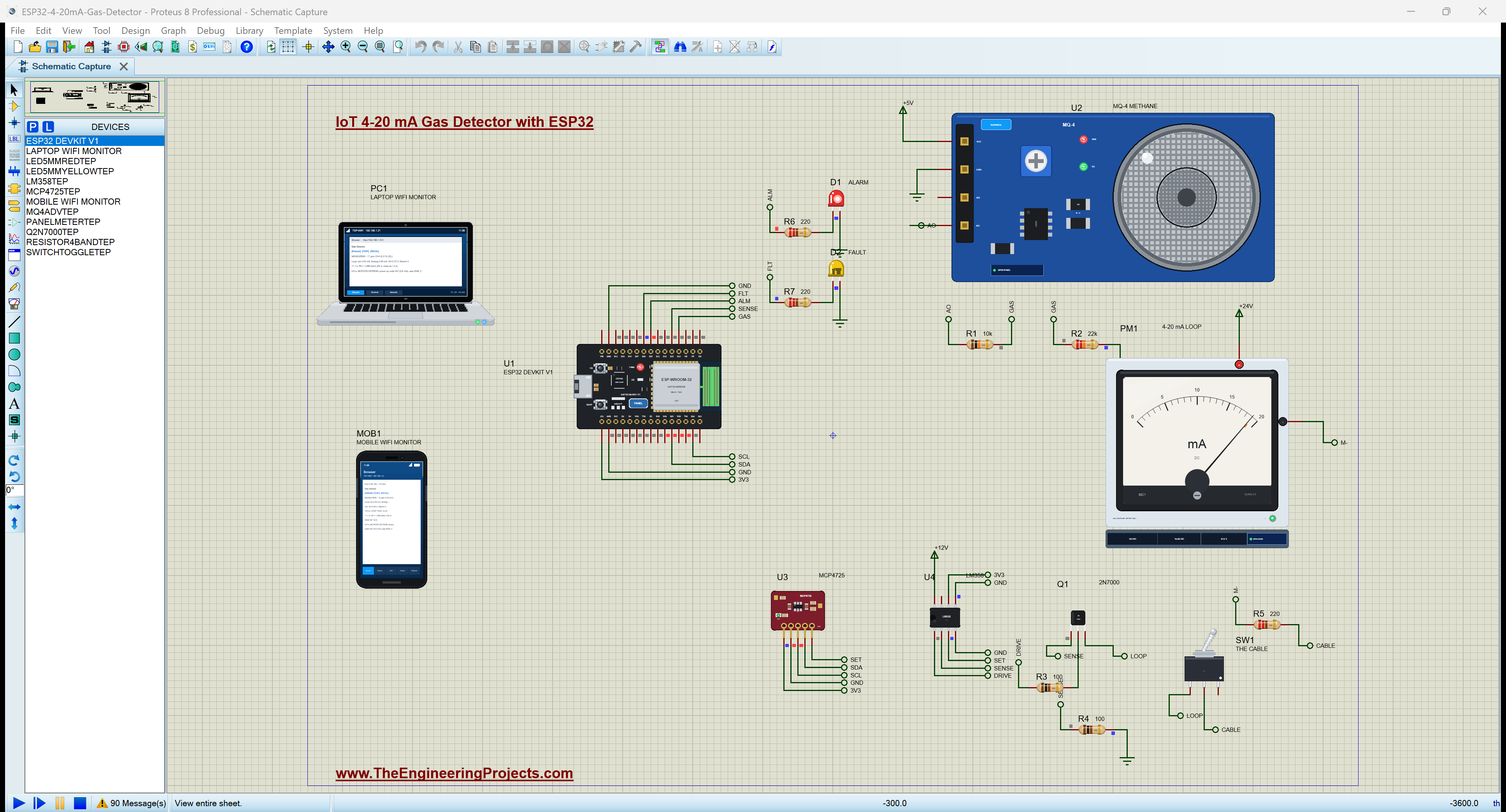
Proteus Simulation of the Gas Detector: the Circuit
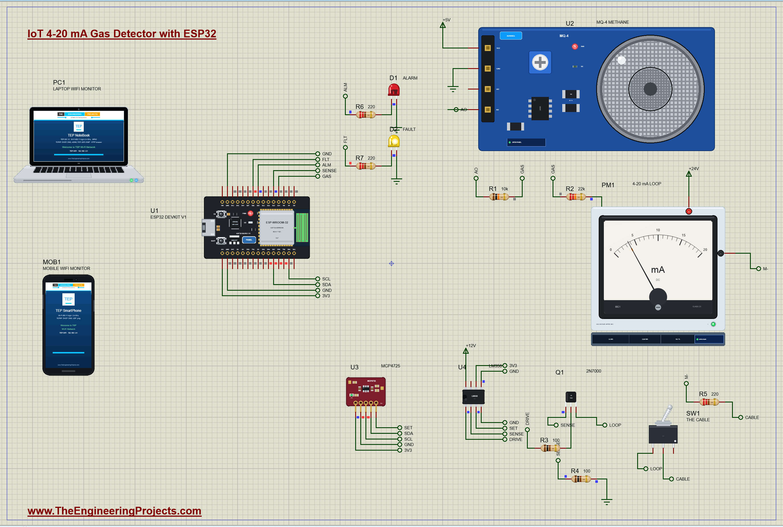
| Part | Pins | ESP32 / other |
|---|---|---|
| U2 MQ-4 | VCC / GND / AO | +5 V / GND / R1 10k - D34 (the net GAS), R2 22k to GND |
| U3 MCP4725 | VCC / GND / SCL / SDA / VOUT | 3V3 / GND / D22 / D21 / the net SET |
| U4 LM358 | V+ / V- / IN1+ / IN1- / OUT1 | +12 V / GND / SET / SENSE / R3 100 ohm to Q1's gate |
| Q1 2N7000 | S / D | SENSE (R4 100 ohm to GND, read on D35) / the loop |
| The loop | +24 V - PM1 + / - - R5 220 ohm - SW1 C / 1 - Q1's drain | |
| D1 / D2 | A / K | D25 / D26 through R6 / R7 220 ohm / GND |
The circuit has two halves. On the left is the field device, the transmitter: the ESP32, the sensor and the converter that sets the current. On the right is what would sit in the control room: the 24 V loop supply, the panel meter that shows the current, and the 220 ohm resistor that stands for the input of a PLC or a recorder. Between them runs the cable, and the toggle switch lets us cut it.
How the 4-20 mA Gas Detector Works
Why a Current, and Why 4 mA?
A voltage signal changes along a long cable: every metre of wire has resistance, and a few ohms with some current flowing is already a measurable drop. A current is the same everywhere in a series loop, so the receiver at the far end sees exactly the current the transmitter set, whatever the cable's resistance, as long as the supply is high enough. The loop is also hard to disturb: noise picked up by the cable has to push current through a low-impedance receiver. The range starts at 4 mA rather than 0 for a simple reason: 0 mA must mean that something is wrong. A cut wire, a dead supply or a dead transmitter all give zero, and the receiver can tell that apart from a true zero reading at 4 mA. That "live zero" also leaves the transmitter 4 mA to power itself in two-wire designs. The NAMUR NE43 recommendation goes one step further: a reading lives between 3.8 and 20.5 mA, and a transmitter signals a fault by going below 3.6 mA or above 21 mA. Our detector uses 3.6 mA while its sensor warms up and when the sensor fails.
Measuring Methane with the MQ-4
The MQ-4 has a heated tin dioxide element whose resistance Rs falls when methane reaches it. The module puts Rs in series with a 1 kohm load resistor RL across 5 V, so the voltage AO across RL rises with the gas. Our divider of 10 kohm and 22 kohm brings AO into the ESP32's 3.3 V range, and because the divider sits across RL, the sketch uses RL in parallel with 32 kohm, 0.970 kohm, to work Rs out exactly. After the warm-up, in clean air, the sketch takes R0 = Rs / 4.4, the clean-air ratio of the MQ-4, and from then on the methane is ppm = 1012.7 x (Rs / R0)^-2.786, the curve of the MQUnifiedsensor examples. Worked example: in the simulation, clean air gives Rs = 6 kohm, so R0 = 1.364 kohm; AO = 5 V x 0.970 / (6 + 0.970) = 0.696 V and D34 sees 0.478 V. At 5,000 ppm Rs / R0 falls to 0.564, Rs = 0.769 kohm, AO rises to 2.79 V and D34 to 1.92 V.
From Gas to Current: the DAC, the Op-Amp and the MOSFET
The sketch maps 0 to 10,000 ppm onto 4 to 20 mA: mA = 4 + 16 x ppm / 10,000. The MCP4725 turns a 12-bit code into a voltage, VOUT = 3.3 V x code / 4096, and the LM358 and the 2N7000 turn that voltage into the current. The op-amp drives the MOSFET's gate until the voltage on the 100 ohm sense resistor at its source equals the DAC's voltage on its other input; all the loop current flows through that resistor, so the current is VOUT / 100 ohm, whatever the panel meter, the receiver and the cable add to the loop. Worked example: 12 mA needs 1.2 V on the sense resistor, so the code is 1.2 / 3.3 x 4096 = 1489; 4 mA is code 496, 20 mA is code 2482, and the 3.6 mA fault current is code 447. One step of the DAC is 0.81 mV, 8 microamperes in the loop: far finer than the meter can show.
Reading the Loop Back: Finding a Cut Cable
A transmitter that only sets its current never knows whether anybody receives it. Ours measures the voltage on the sense resistor with D35, sixteen readings averaged, and divides it by 100 ohm: that is the current that really flows. If 3.5 mA or more is asked for but less than 1 mA flows for 0.3 s, the loop is open, and the FAULT LED and the dashboard say so. When the cable is joined again, the current comes back and the fault clears by itself.
The Loop's Voltage Budget
Everything in the loop takes a share of the 24 V supply. At 20 mA the panel meter takes 0.1 V (its shunt is 5 ohm), the 220 ohm receiver 4.4 V and the sense resistor 2.0 V; the MOSFET takes the remaining 17.5 V and turns 0.35 W into heat. That is inside the 2N7000's 0.4 W, but not by much: in a warm cabinet a real design would use a MOSFET in a bigger package, a lower supply or more loop resistance. The other limit is the compliance: if the loop resistance grew so much that the MOSFET had no voltage left, the current could no longer reach its target, and the read-back would show the difference.
The Arduino Code Explained
The whole sketch is included in the download. It uses Wire for the MCP4725, analogRead for the sensor and the read-back, and the WebServer library for the dashboard. At the top are the sensor's curve and the output's scale:
const float CLEAN_RATIO = 4.4, A_CH4 = 1012.7, B_CH4 = -2.786;      // MQ-4, methane: ppm = A x (Rs / R0)^B
const float SPAN_PPM = 10000, ALARM_PPM = 5000, CLEAR_PPM = 4000;  // 20 mA = 10,000 ppm = 20 % LEL; the alarm at 10 % LEL
The Sensor
aoV = avgVolts(GAS_PIN) * (R_TOP + R_BOT) / R_BOT; // undo the divider: the module's AO return RL_EFF * (VCC_MQ - aoV) / aoV; // AO = VCC x RL_EFF / (Rs + RL_EFF) r0 = s / 10 / CLEAN_RATIO; if (!sensorFault) ppm = A_CH4 * pow(rs / r0, B_CH4);The Current
long c = lround(mA / 1000.0 * R_SENSE / VREF * 4096); Wire.beginTransmission(DAC); Wire.write((c >> 8) & 0x0F); Wire.write(c & 0xFF); Wire.endTransmission(); out = sensorFault ? FAULT_MA : min(OVER_MA, (float)(4.0 + 16.0 * ppm / SPAN_PPM));At power-up the sketch also stores the 3.6 mA code in the MCP4725's EEPROM with the "write DAC register and EEPROM" command, 0x60, so that after any reset the loop starts at the fault current instead of the factory middle scale, which would read as 7,800 ppm:
Wire.beginTransmission(DAC); Wire.write(0x60); Wire.write(c >> 4); Wire.write((c & 0x0F) << 4); Wire.endTransmission();The Loop Check
readMa = avgVolts(SENSE_PIN) / R_SENSE * 1000; // the current that really flows in the loop if (setMa >= 3.5 && readMa < 1.0) { // the loop check: the current set does not flowThe pages are / (the dashboard), /test (the loop test), /recal (a new R0, in clean air only) and /data (JSON). The dashboard puts its links first and stays short, because the WiFi Monitors show one screen of a page.
How to Run the Proteus Simulation
- Download the project zip below and install the library files (the steps are under the download button).
- Open ESP32-4-20mA-Gas-Detector.pdsprj from the Proteus Simulation folder. Keep the HEX and the DLL files next to it.
- Press Play. The MQ-4 warms up for about 10 s: the FAULT LED blinks and the panel meter shows 3.6 mA. Then clean air reads about 4.03 mA.
- In the MQ-4's pop-up choose a preset, 1000, 5000 or 10000 ppm CH4, or LEAK; VENTILATE brings fresh air.
- Click the toggle switch to cut the cable and again to join it.
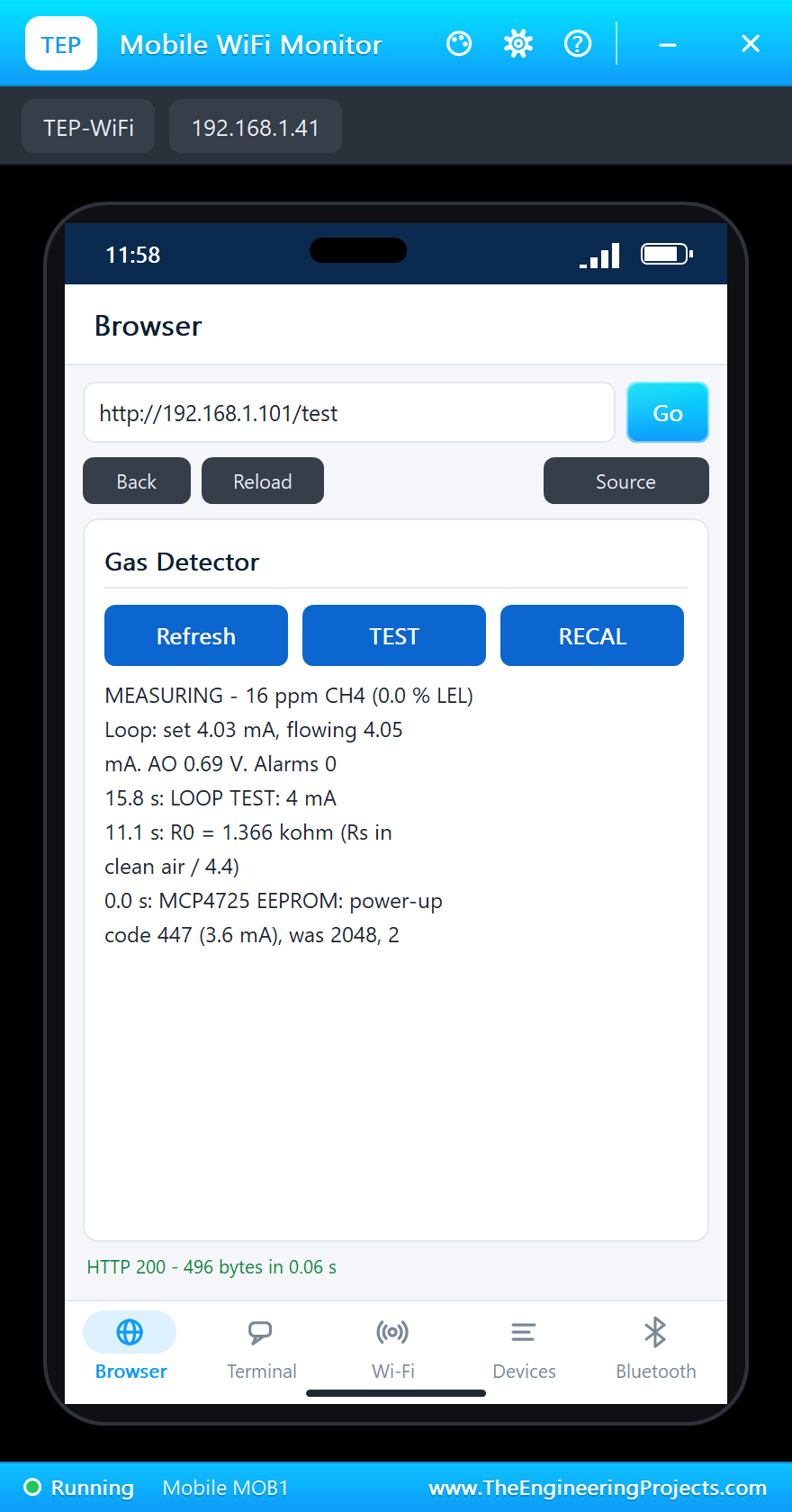
- Open the Laptop WiFi Monitor (PC1) or the Mobile WiFi Monitor (MOB1) and press Go: TEST and RECAL.
Simulation Results: the 4-20 mA Gas Detector in Proteus
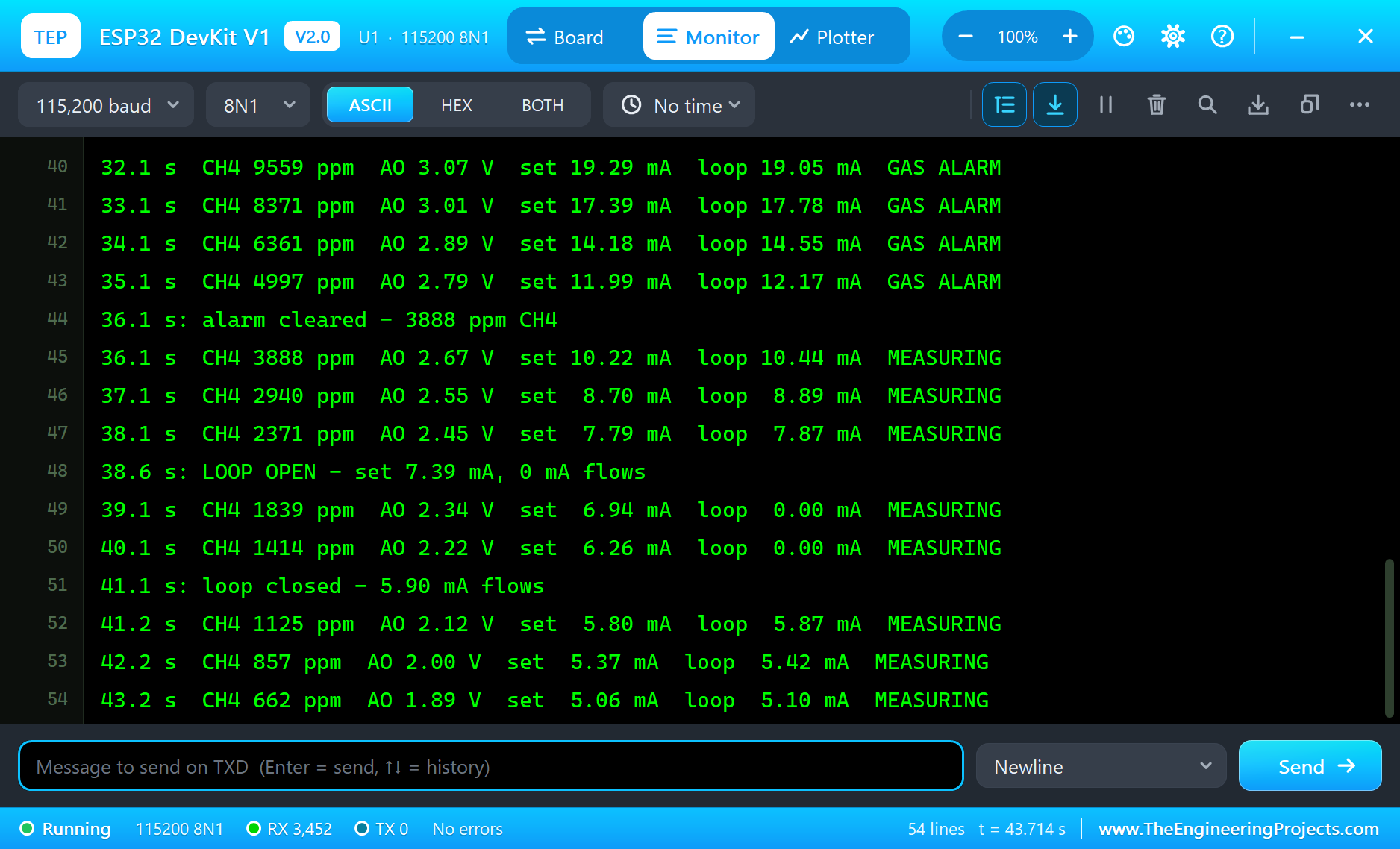
Here is the run that made the screenshots of this tutorial, 43.8 seconds of simulation. The times are the sketch's own, the seconds since the ESP32 started, as it printed them on its serial monitor.
Power-Up and the Warm-Up
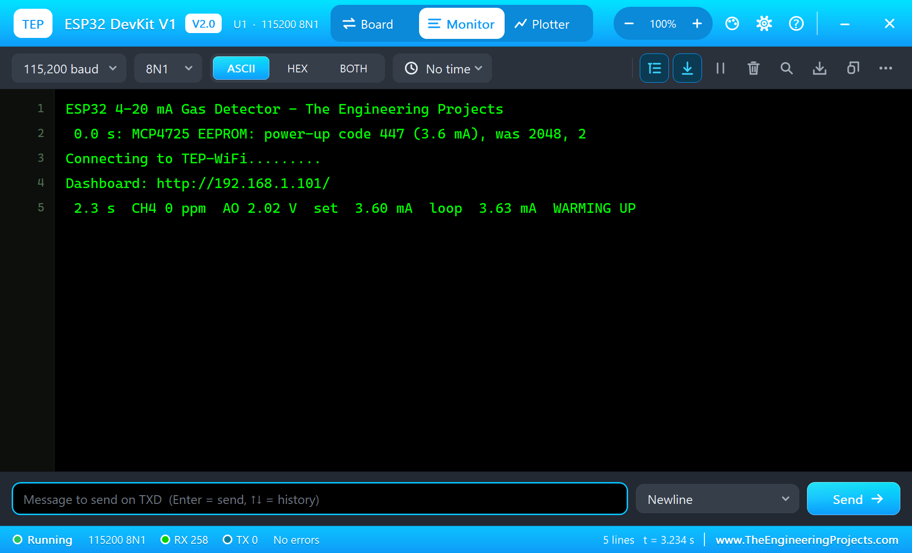
The first thing the sketch does is look at the MCP4725's EEPROM: it still holds the factory code 2048, so the sketch writes 447 there, the 3.6 mA fault current, and the DAC register with it. From now on a reset can never make the loop show a false gas reading. Then the MQ-4 warms up. Its heater makes the sensing resistance far too low at first, so AO starts high, 2.02 V at 2.3 s, and falls to the clean-air 0.70 V within about seven seconds. All that time the loop carries 3.60 mA, read back as 3.63 mA, and the yellow FAULT LED blinks.
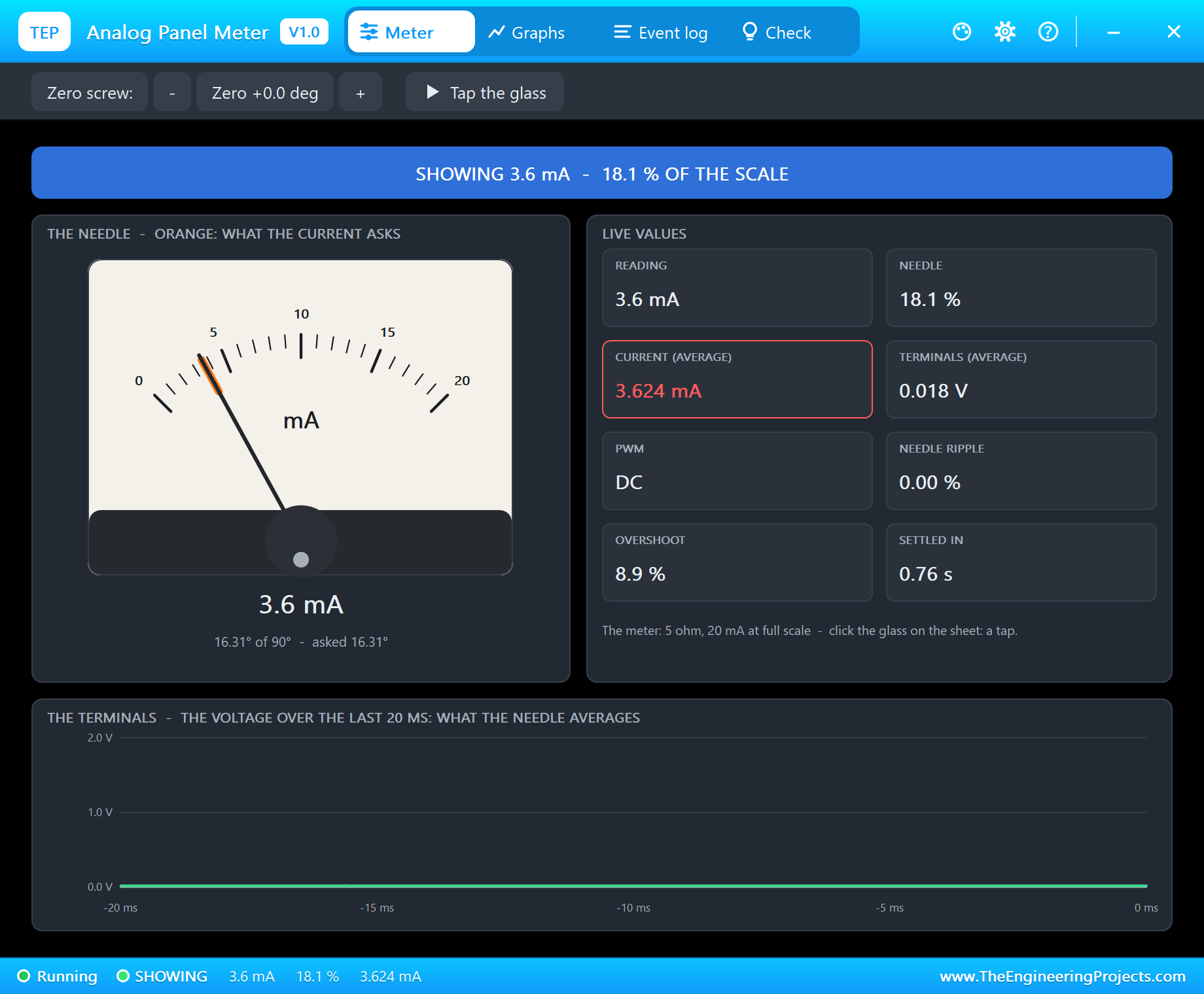
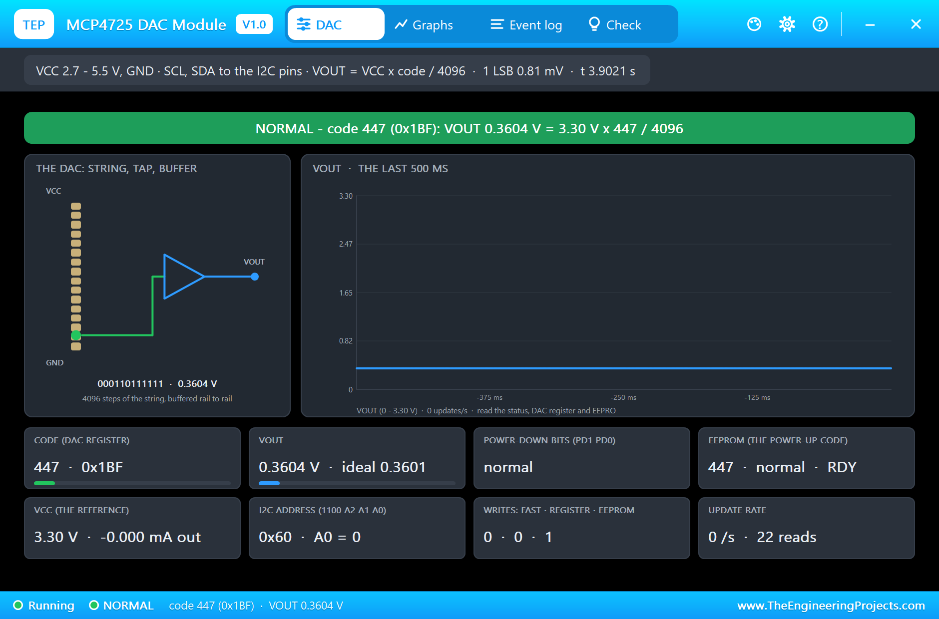
Clean Air: 4.03 mA
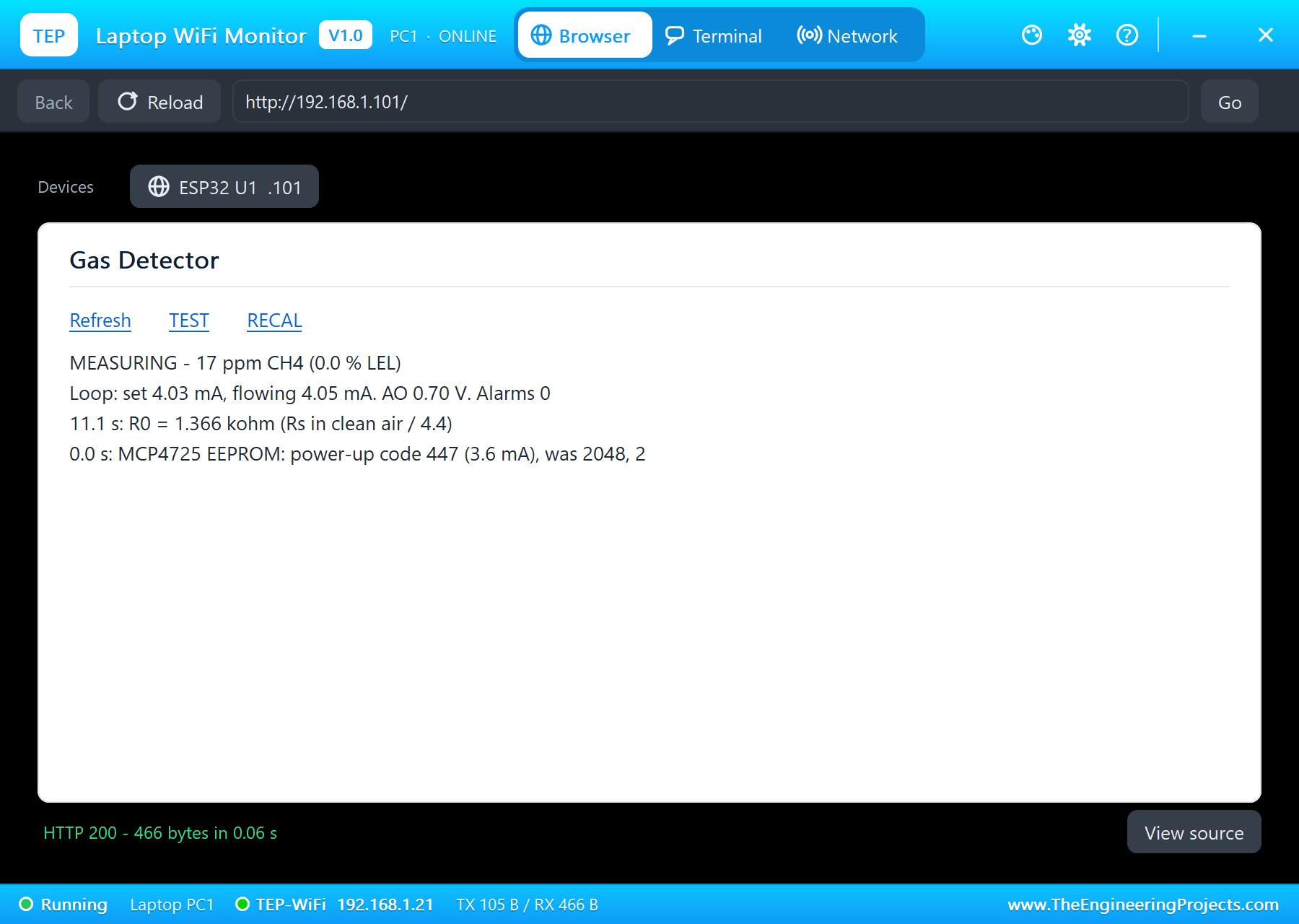
At 11.1 s the warm-up is over and the sketch calibrates: "R0 = 1.366 kohm (Rs in clean air / 4.4)", within 0.2 % of the 1.364 kohm the model uses. Clean air then reads 16 ppm of methane, the baseline of the MQ-4's curve, and the loop is set to 4.03 mA. The read-back says 4.05 mA: the LM358's input offset of about 2 mV adds 0.02 mA through the 100 ohm sense resistor, exactly the kind of small error a real transmitter trims at the factory. The panel meter shows the same 4.05 mA.
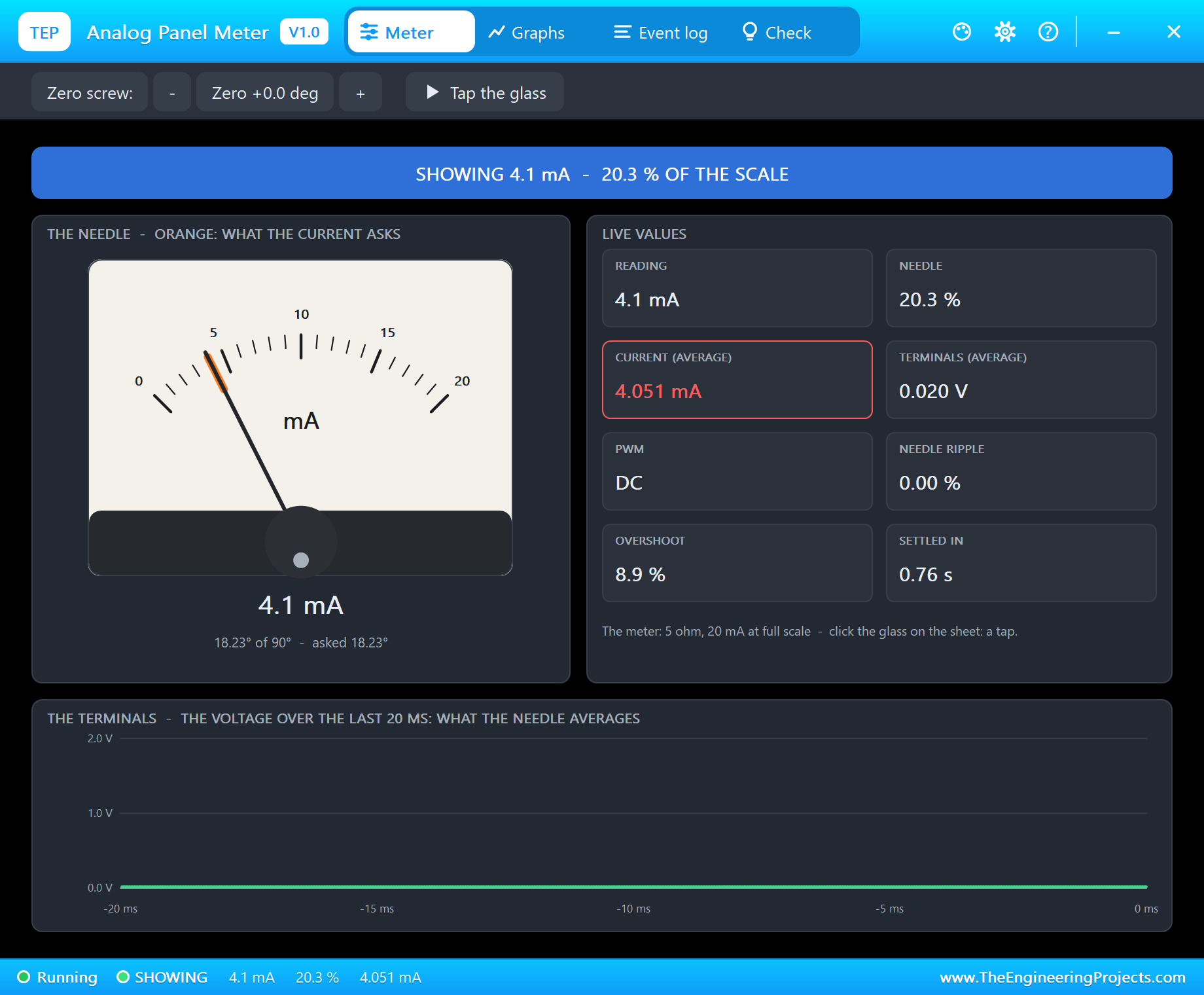
The Loop Test
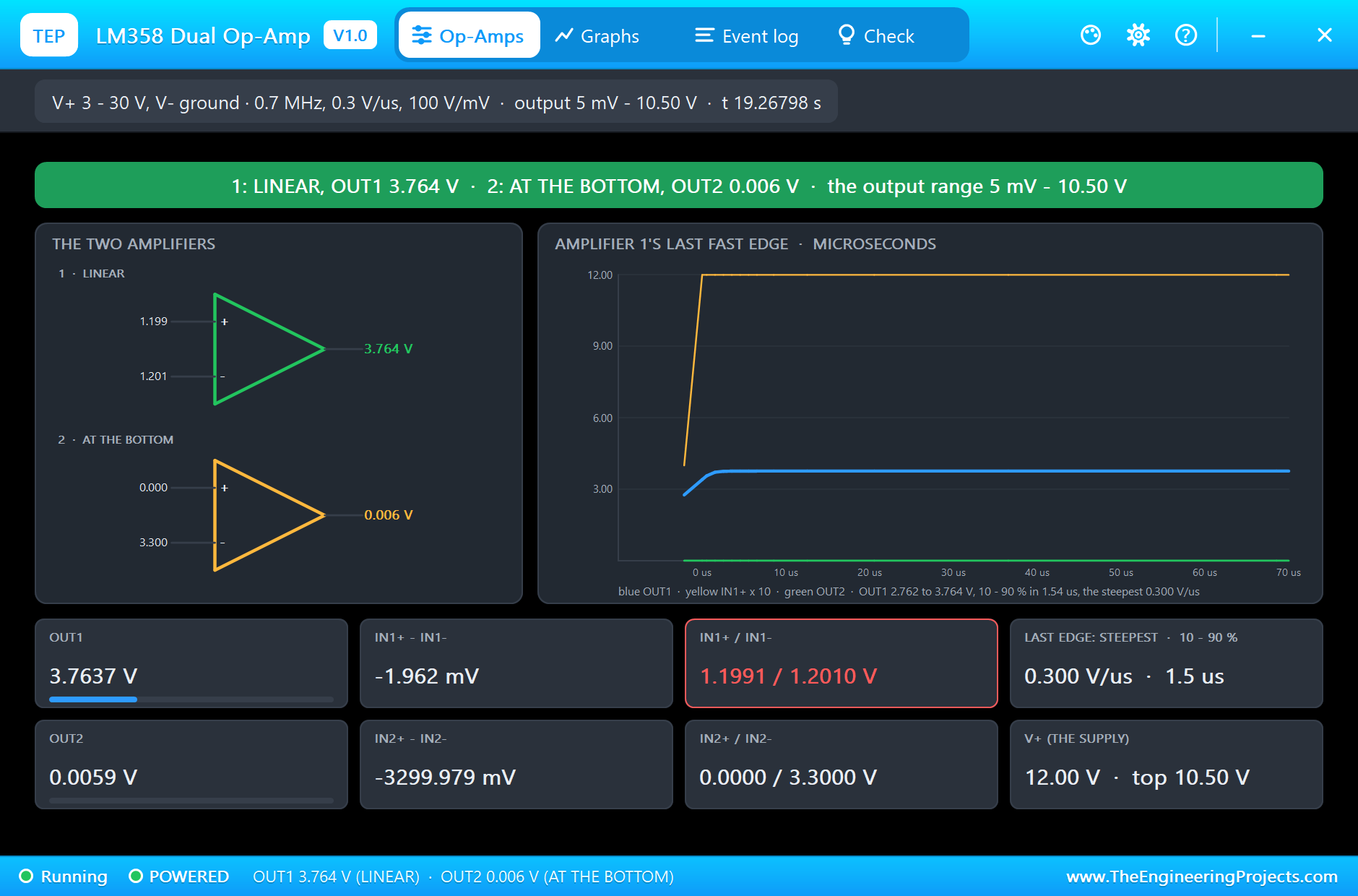
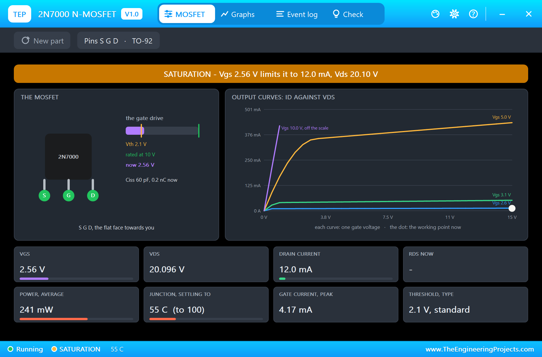
At 15.8 s TEST on the phone starts the loop test: 4 mA, 12 mA and 20 mA for two seconds each. The read-back follows every step: 4.00 mA set and 4.02 mA flowing, 12.00 and 12.01 mA, 20.00 and 20.00 mA. At 12 mA the LM358 holds its two inputs 1.96 mV apart, 1.199 V and 1.201 V, with 3.76 V on the 2N7000's gate, and the MOSFET drops 20.1 V at 241 mW, its junction warming towards 100 C. That confirms the voltage budget: at 20 mA it would dissipate about 0.35 W, which is why a long stay at full scale wants a bigger MOSFET.
A Gas Leak
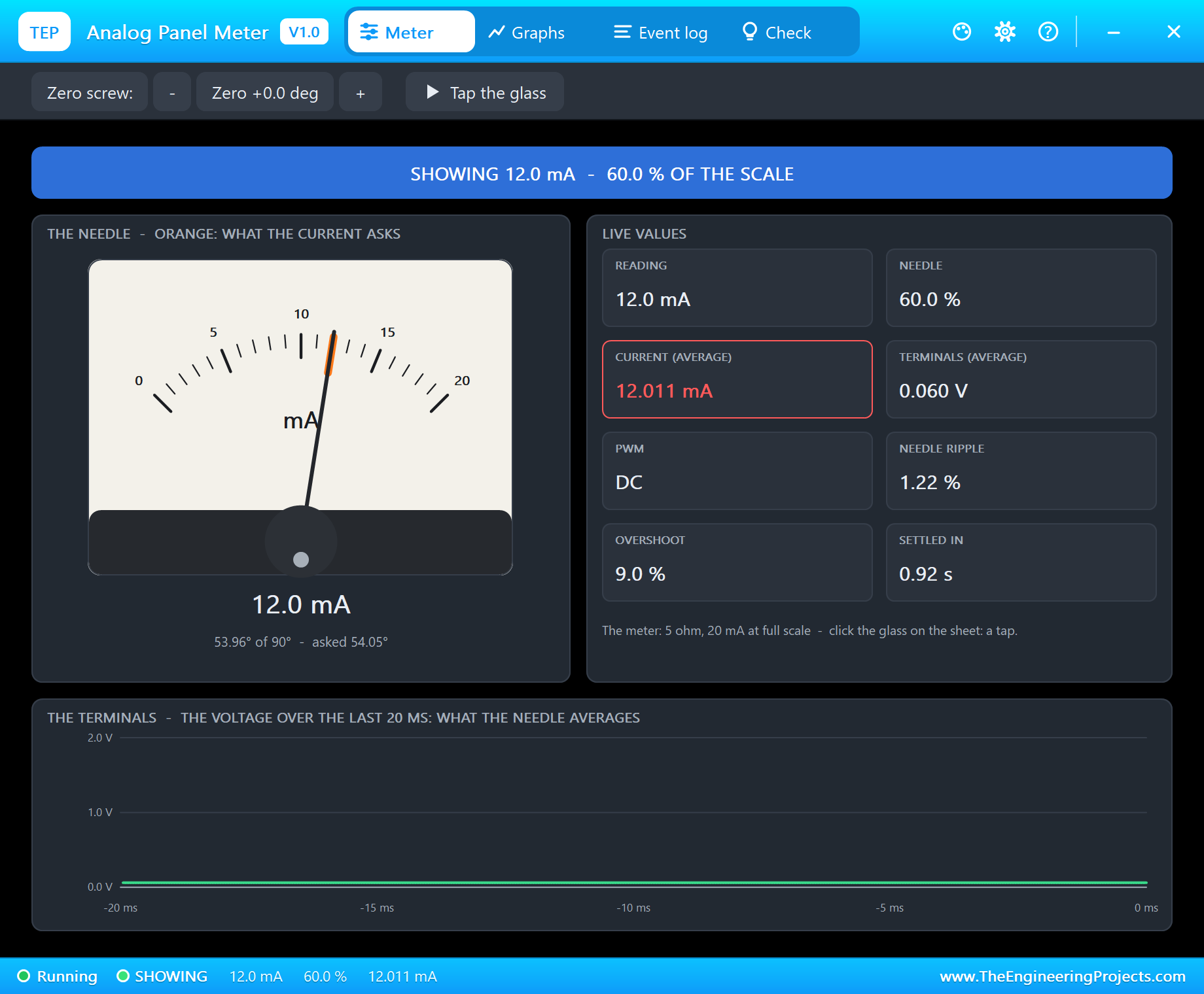
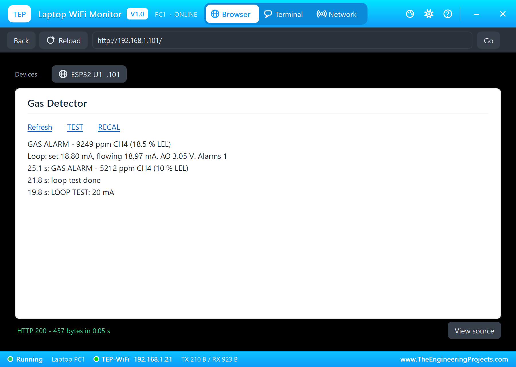
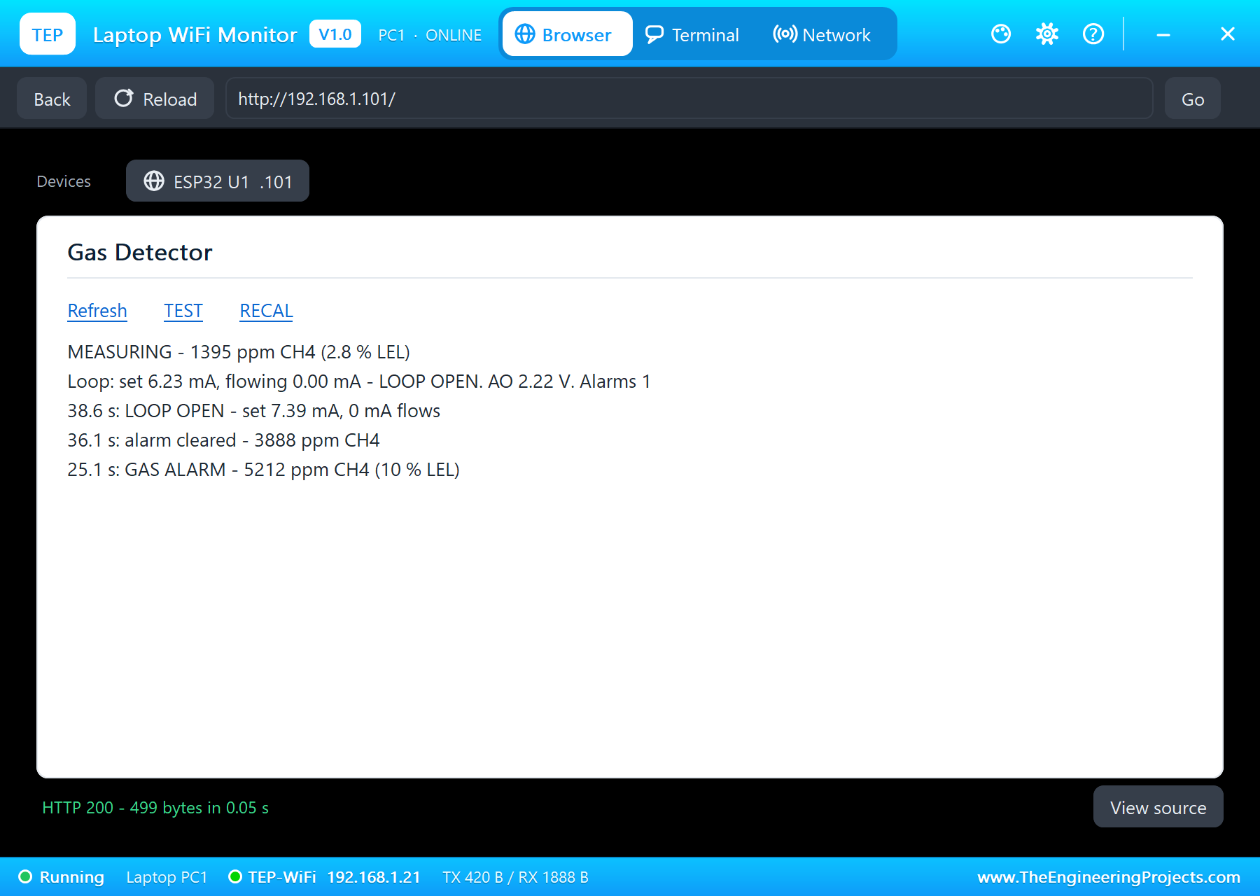
At 23.1 s the MQ-4's pop-up puts 10,000 ppm of methane in the air. The gas reaches the sensor with its lag, and the reading climbs: 364 ppm, 3,100 ppm, then at 25.1 s "GAS ALARM - 5212 ppm CH4 (10 % LEL)": the red ALARM LED lights and the loop passes 12 mA. The reading keeps climbing towards the 10,000 ppm in the air: 9,559 ppm at 32.1 s, the loop set to 19.29 mA, the needle near 19 mA. The dashboard shows the gas in ppm and in percent of the lower explosive limit, 18.5 % LEL when the laptop refreshed.
Fresh Air
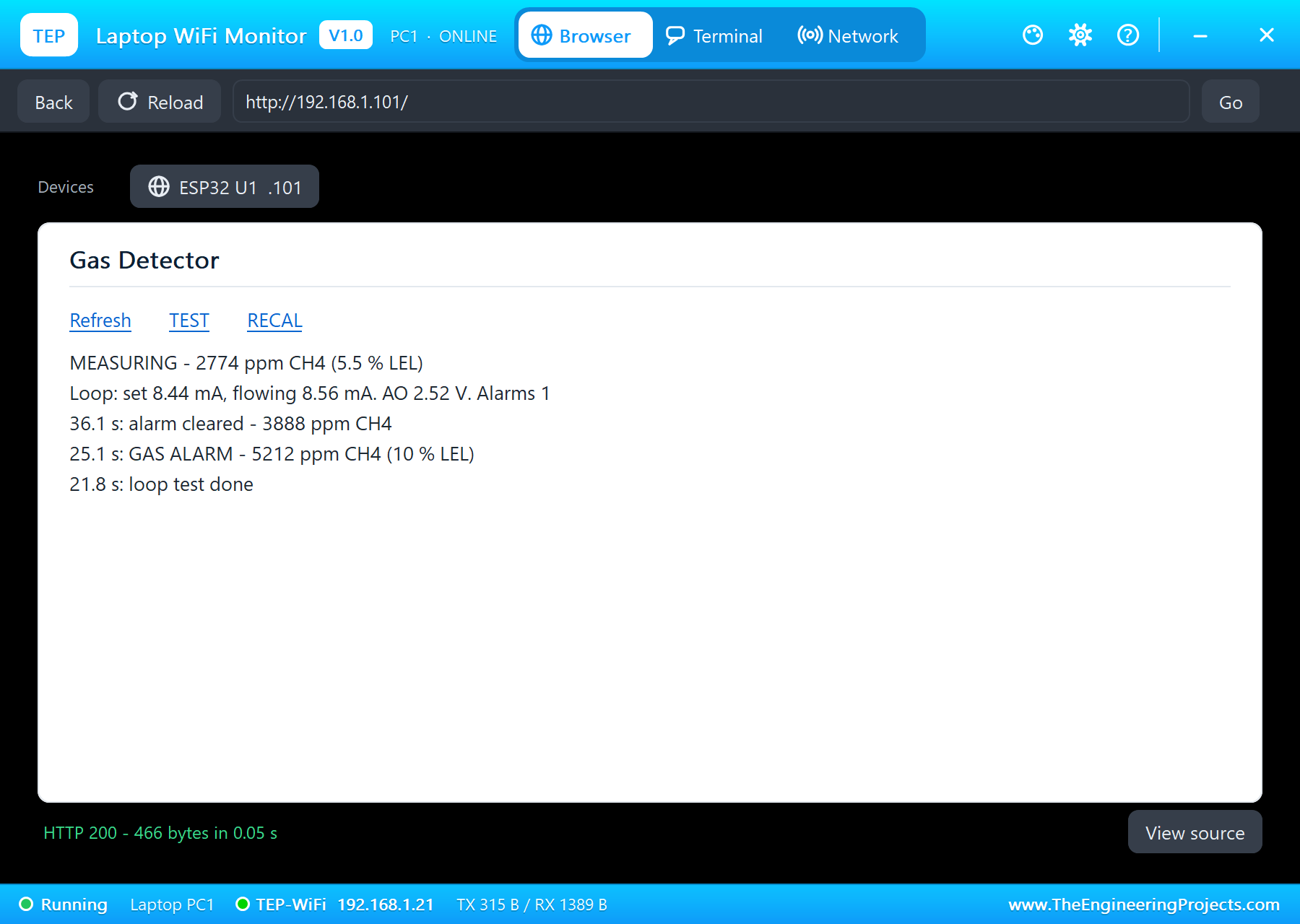
At 32.6 s VENTILATE brings fresh air. The sensor needs longer to clear than to react, and the reading falls: 8,371, 6,361, 4,997 ppm, and at 36.1 s "alarm cleared - 3888 ppm CH4", below the 4,000 ppm level where the alarm resets. The 1,000 ppm between the alarm and its reset keeps the LED from flickering when the gas hovers near 5,000 ppm.
A Cut Cable
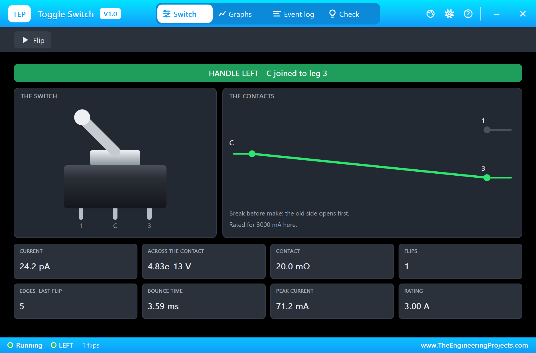
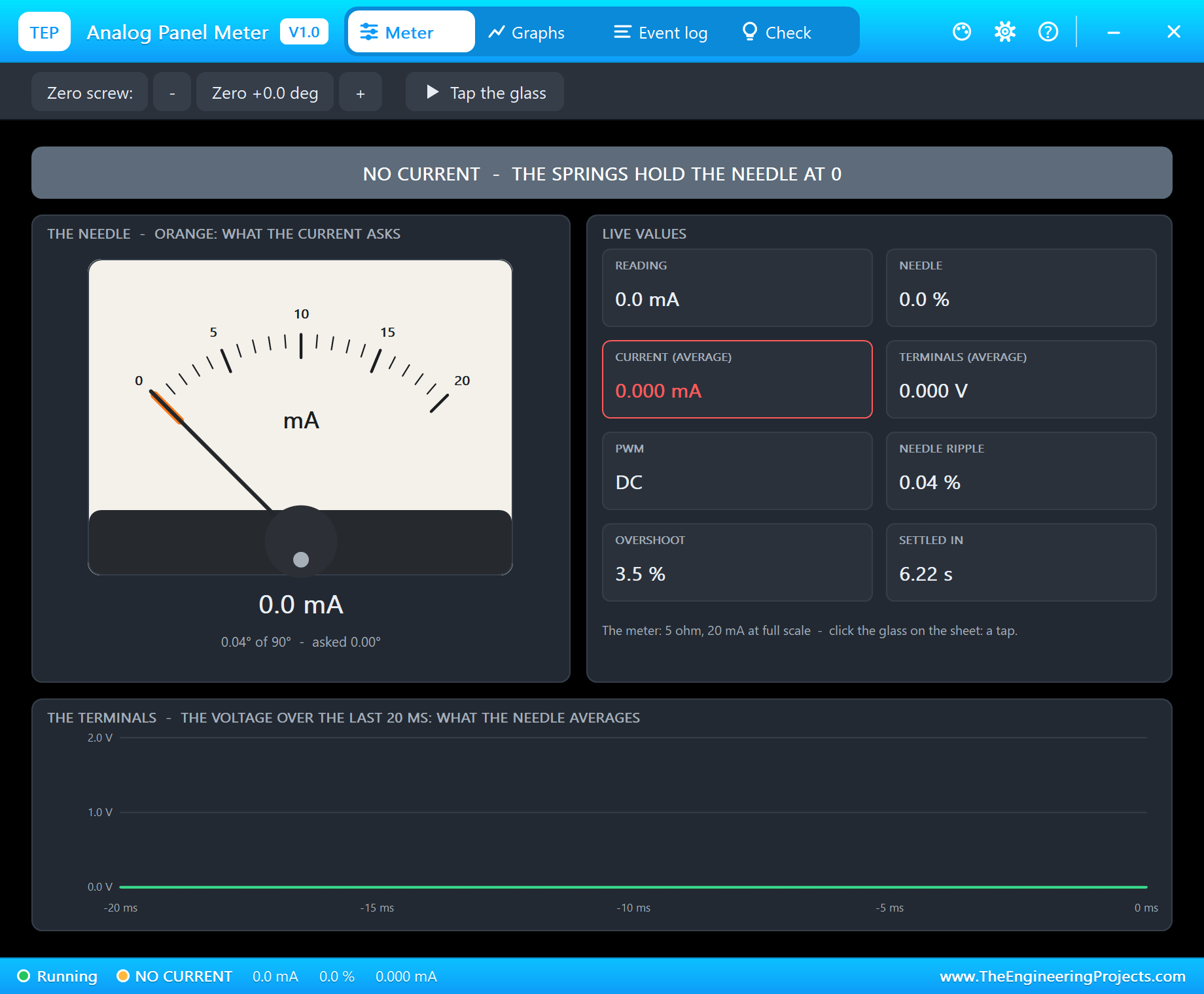
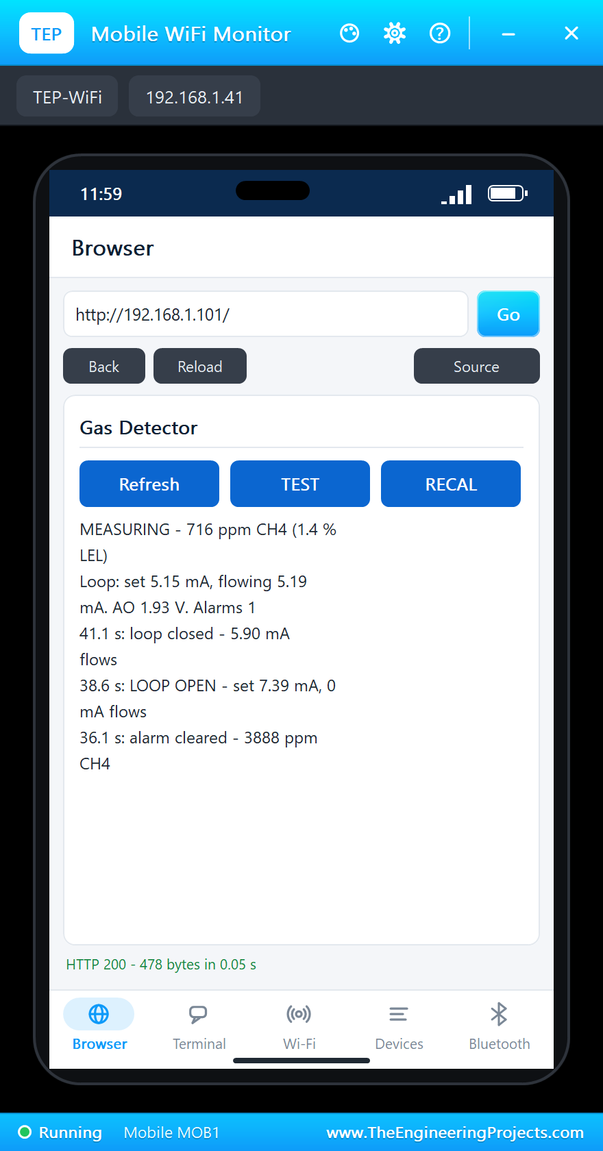
At 38.2 s the toggle switch cuts the cable. The DAC still asks for 7.39 mA, but nothing can flow: the sense resistor reads 0 mA, and 0.3 s later the sketch reports "LOOP OPEN - set 7.39 mA, 0 mA flows". The yellow FAULT LED lights, the dashboard shows LOOP OPEN, and in the control room the panel meter falls to NO CURRENT, below the live zero, so the operator knows at once that this is a fault and not clean air. At 41.1 s the switch joins the cable again: "loop closed - 5.90 mA flows", and the detector carries on measuring as the gas clears.
The Numbers of the Run
| What | Result |
|---|---|
| Warm-up | 3.60 mA set, 3.63 mA flowing; AO 2.02 V falling to 0.70 V |
| Clean air | R0 1.366 kohm; 16 ppm; 4.03 mA set, 4.05 mA flowing |
| Loop test | 4.00 / 4.02, 12.00 / 12.01, 20.00 / 20.00 mA |
| Gas alarm | 5,212 ppm at 25.1 s; 9,559 ppm and 19.29 mA at 32.1 s |
| Alarm cleared | 3,888 ppm at 36.1 s |
| Cable cut | LOOP OPEN 0.4 s after the cut; closed again at 41.1 s |
| Simulation | 43.8 s of simulation |
Download the Project Files
Click the button below to download IoT-4-20mA-Gas-Detector-ESP32-Proteus-Simulation-v1.0.zip (about 5.3 MB, without the source code of the models):
ESP32 4-20 mA Gas Detector with an MQ-4 Sensor - Proteus Simulation V1.0- Proteus Simulation: ESP32-4-20mA-Gas-Detector.pdsprj, the HEX file and copies of the models.
- Arduino Code: ESP32_Gas_Detector.ino, the complete sketch.
- Proteus Library Files: the LIB files of the ESP32, the MQ sensors, the MCP4725, the LM358, the MOSFETs, the panel meter, the toggle switch, the LED, the resistor and the two WiFi Monitors.
- Proteus Model Files: the DLL models.
- README.txt: the installation steps, the properties, the test results and the links to every library post.
No Proteus yet? Read How to Download and Install Proteus 7 and 8. New to libraries? Follow How to Install a New Library in Proteus.
How to Install the Project Files
- Close Proteus and extract the whole zip file, for example to your Desktop.
- Copy the files from Proteus Library Files into the LIBRARY folder of Proteus.
- Copy the files from Proteus Model Files into the MODELS folder.
- Start Proteus and open the project from the Proteus Simulation folder.
Changing the Code
Open ESP32_Gas_Detector.ino in the Arduino IDE with the ESP32 boards installed, change it, use Sketch > Export Compiled Binary and set U1's PROGRAM property to the new HEX file. The range, the alarm levels and the fault currents are at the top. On a real ESP32 the ADC is not quite linear near its ends: calibrate the read-back against a multimeter. For our other gas project, with an MQ-2 and a flame sensor on a Raspberry Pi, see the Raspberry Pi 5 Gas Leak and Fire Alarm.
Ideas to Extend the Project
- Add a HART-style digital channel or Modbus over RS485 next to the analog loop.
- Make it a true two-wire transmitter powered by its own loop current.
- Log the gas and the loop current over time and draw them on the dashboard.
- Latch the alarm until a technician acknowledges it, as many fixed detectors do.
- Add a relay for a ventilation fan or a gas valve at the alarm level.
- Read the loop on another ESP32 as the control room, through a 250 ohm resistor.
From Simulation to Real Hardware
- Warm-up and burn-in: a real MQ-4 needs minutes to warm up and a day or two of burn-in before its readings settle.
- Not a certified detector: for real safety use a certified catalytic or infrared methane detector; the MQ-4 is a learning sensor.
- Calibrate with gas: set R0 in clean air and check the reading with a known calibration gas.
- Mind the MOSFET's heat: 0.35 W at 20 mA on 24 V is close to the 2N7000's limit.
- Protect the loop: real transmitters add a fuse, a reverse-polarity diode and surge protection on the loop terminals.
Troubleshooting
- The loop stays at 3.6 mA: the sensor is still warming up, or AO reads 0 V and the sketch reports a sensor fault.
- LOOP OPEN with the switch closed: no 24 V supply, or the meter or the receiver resistor is not in the loop.
- The current differs from the one set: SET and SENSE are swapped at the op-amp, or the sense resistor is not 100 ohm.
- The ppm is far off in clean air: RECAL was pressed in gas; R0 is taken from the air at that moment.
Limitations of the Simulation
- The MQ-4's warm-up is shortened to 8 s; its curve follows the MQUnifiedsensor example, not a particular sensor.
- The gas is set in the pop-up; a real leak spreads unevenly and the sensor sees only the air at its cap.
- The network is simulated: the dashboard travels between the ESP32 and the two monitors inside Proteus; the times in this tutorial are simulation time.
- ESP32 is a product of Espressif Systems and the MCP4725 of Microchip Technology; the LM358, the 2N7000 and MQ sensors are made by several companies. This project is not made or endorsed by them or by Labcenter.
So, that was all about the ESP32 4-20 mA Gas Detector with an MQ-4 Sensor - Proteus Simulation. I hope it helps you understand the signal that still connects most of the world's industrial sensors: a live zero at 4 mA, a current that ignores the cable, a DAC, an op-amp and a MOSFET that make it precise, and a read-back that catches a cut wire, all tested in a simulation before you connect a single real loop. More IoT projects with the ESP32 and the Raspberry Pi 5 are coming in this series. If you have any questions, ask in the comments and I will help you out. Till the next tutorial, take care and have fun!