Hello friends, I hope you all are doing great. Today, I am going to share the IoT GPS Vehicle Tracker with ESP32 - Proteus Simulation, the ninth project of our IoT Projects series. If you have searched for a Proteus simulation of a GPS tracker with an ESP32, here is a complete one. An ESP32 reads its position, speed and course from a NEO-6M GPS module, watches for a crash or a rollover with an MPU6050 motion sensor, adds up the distance of the trip, warns when the vehicle goes too fast, draws the route, and shows everything on a live web dashboard for your laptop and your phone.
Vehicle trackers are everywhere: in delivery vans, rental cars, buses and school transport, and as theft trackers in private cars. In this tutorial, we will go through the circuit, learn what a GPS receiver actually sends, see how the TinyGPS++ library turns those sentences into numbers, measure tilt and impacts with an accelerometer, walk through the ESP32 code, and then run the simulation: a cold start, a drive at 50 km/h that breaks the speed limit, a rollover and the end of the trip. At the end, you can download the project with the code and every library file it needs.
NOTICE: Our team has put a lot of effort into this project: the circuit, the code and every part in the simulation are our own work, and you get them all free. Your feedback is the fuel that keeps us going, so please tell us what you think in the comments below. And if our free projects help you, you can buy us a coffee. So, let's get started with the IoT GPS Vehicle Tracker with ESP32 - Proteus Simulation:
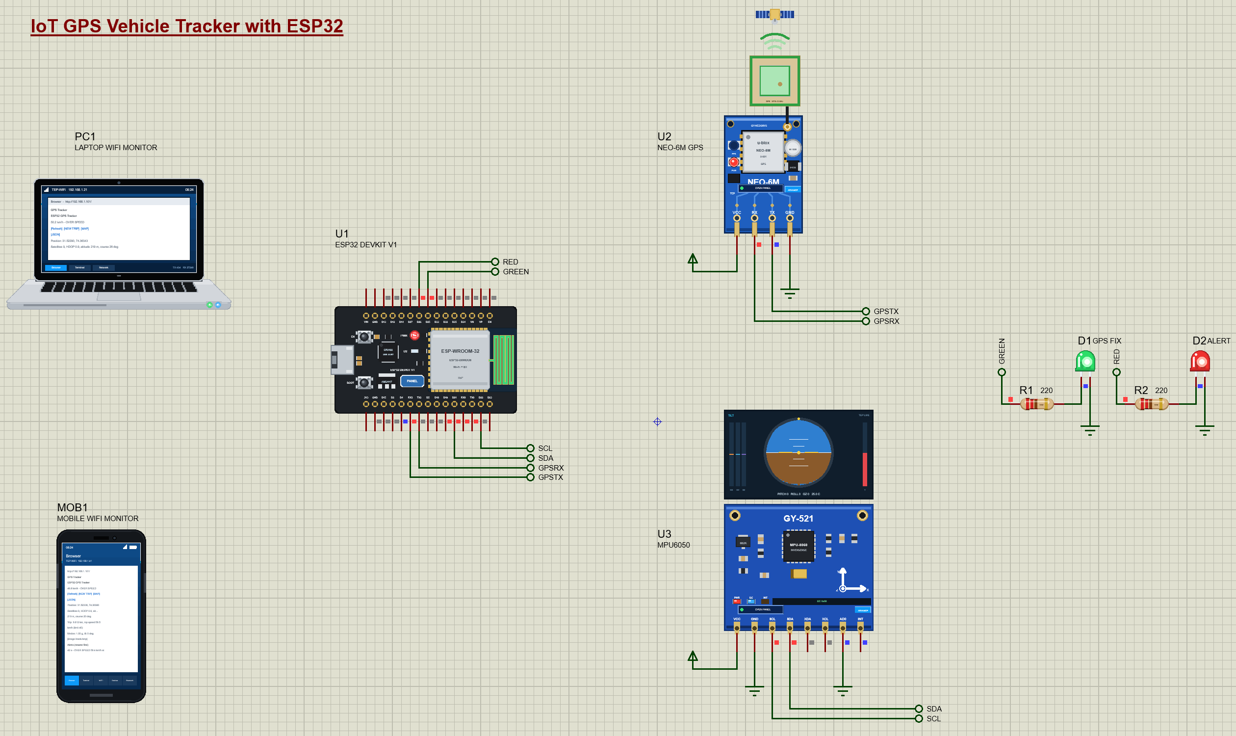
What Does This GPS Vehicle Tracker Do?
The tracker does the jobs of a commercial fleet tracker, on one ESP32:
- Position: the latitude and longitude from the GPS, with a MAP link that opens the place on a map.
- Speed and course: the vehicle's speed in km/h and its heading in degrees.
- Trip: the distance driven, added up between GPS fixes, and the top speed of the trip.
- Speed alarm: OVER SPEED above 40 km/h, logged with the place it happened.
- Crash alarm: an IMPACT for a jolt over 2.5 g and a ROLLOVER for a tilt of more than 60 degrees, each with its position.
- The route: a picture of the last two minutes of the drive, drawn by the ESP32 itself.
- Status LEDs: green blinks while it searches for satellites and stays on with a fix; red lights for an alert.
It is a great project for anyone learning the ESP32, serial GPS modules or motion sensors, and a popular final-year project on vehicle safety. In the simulation, the GPS pop-up can drive the vehicle at the press of a button, so you can test a 50 km/h drive without leaving your desk.
Components Used in the Proteus Simulation
All the parts come from our Proteus libraries, each with its own tutorial. The project zip at the end includes every LIB and DLL file.
| Part | Proteus device | Library post | Connection |
|---|---|---|---|
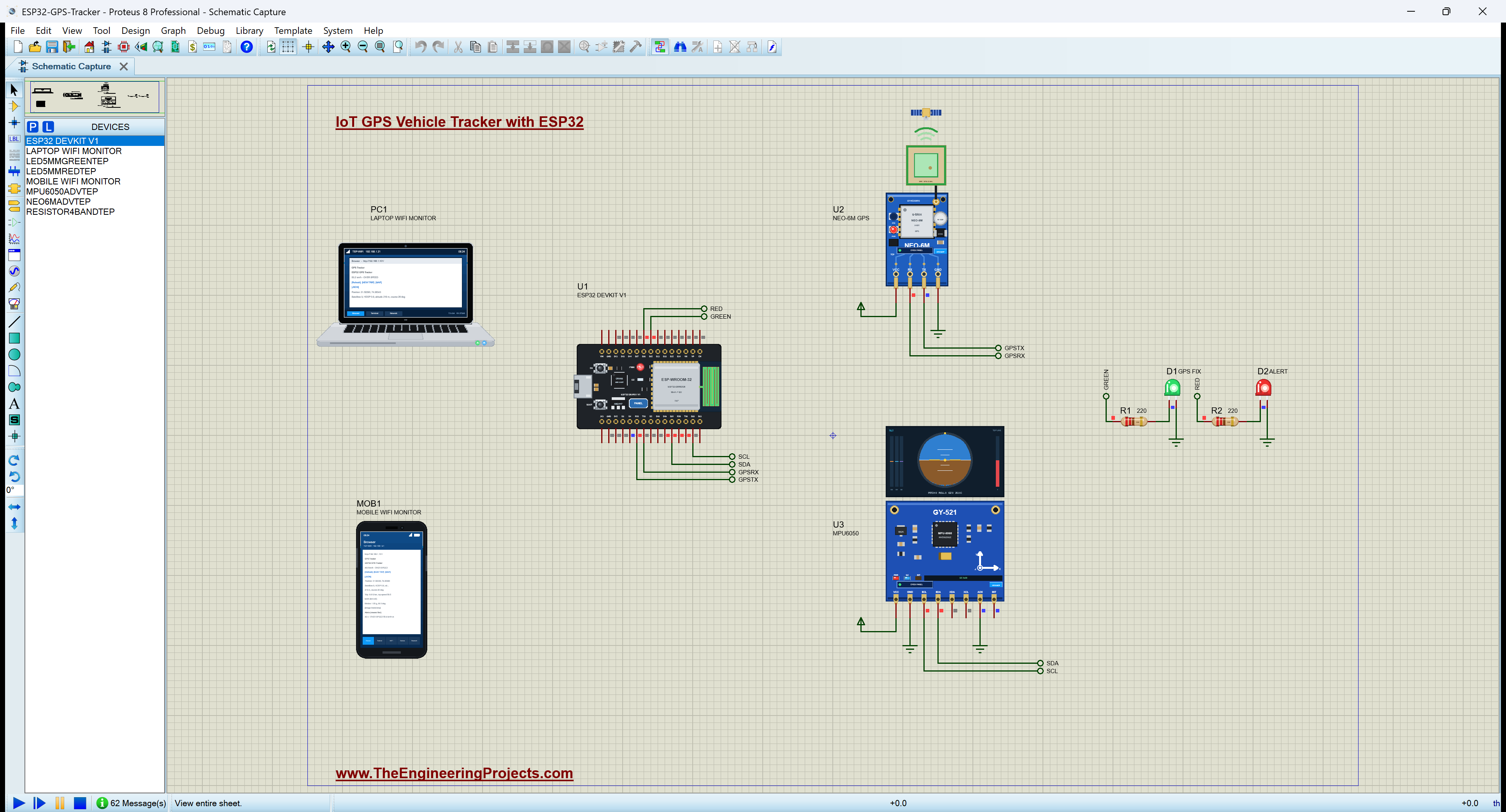
| ESP32 DevKit V1 | ESP32 DEVKIT V1 | ESP32 DevKit V1 Library for Proteus | U1, Wi-Fi 192.168.1.101 |
| NEO-6M GPS module | NEO6MADVTEP | NEO-6M GPS Library for Proteus | U2, TX to RX2 (GPIO16), RX from TX2 (GPIO17) |
| MPU6050 motion sensor (GY-521) | MPU6050ADVTEP | MPU6050 Library for Proteus | U3, I2C 0x68 on D21 / D22 |
| LEDs and resistors | LED5MMGREENTEP, RESISTOR4BANDTEP | 5mm LED Library, Resistor Library | D25 green, D26 red |
| Laptop WiFi Monitor | LAPTOP WIFI MONITOR | Laptop WiFi Monitor | PC1 |
| Mobile WiFi Monitor | MOBILE WIFI MONITOR | Mobile WiFi Monitor | MOB1 |
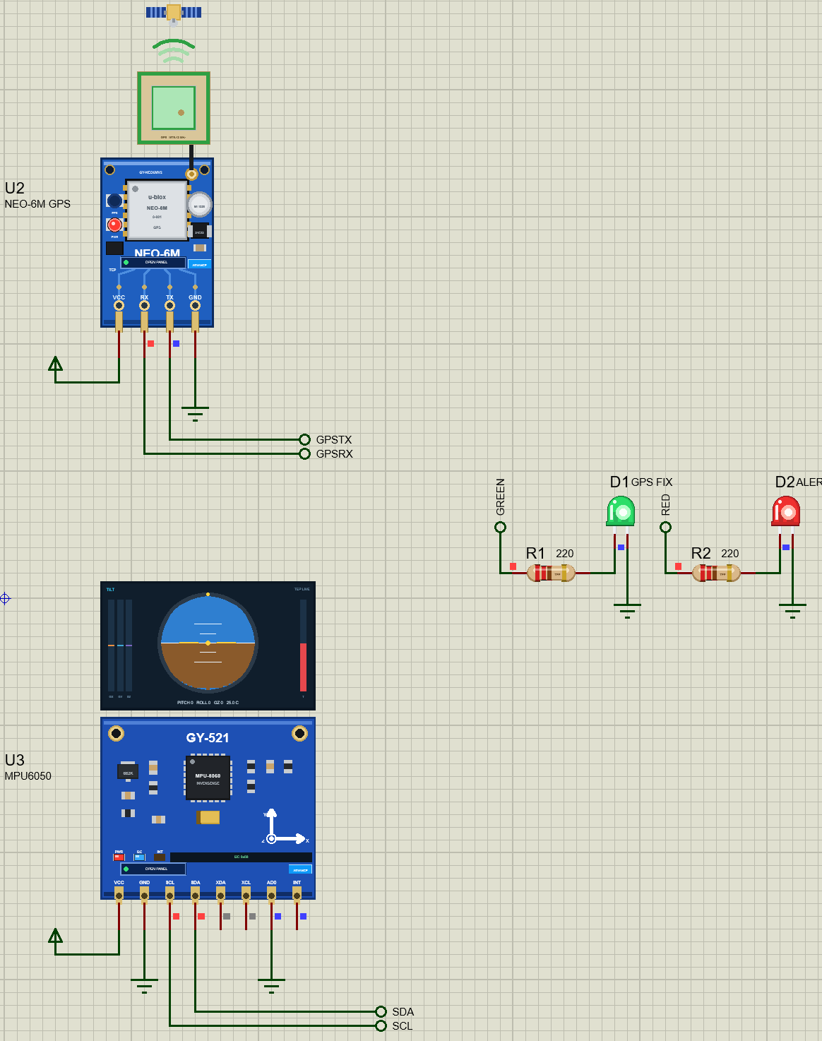
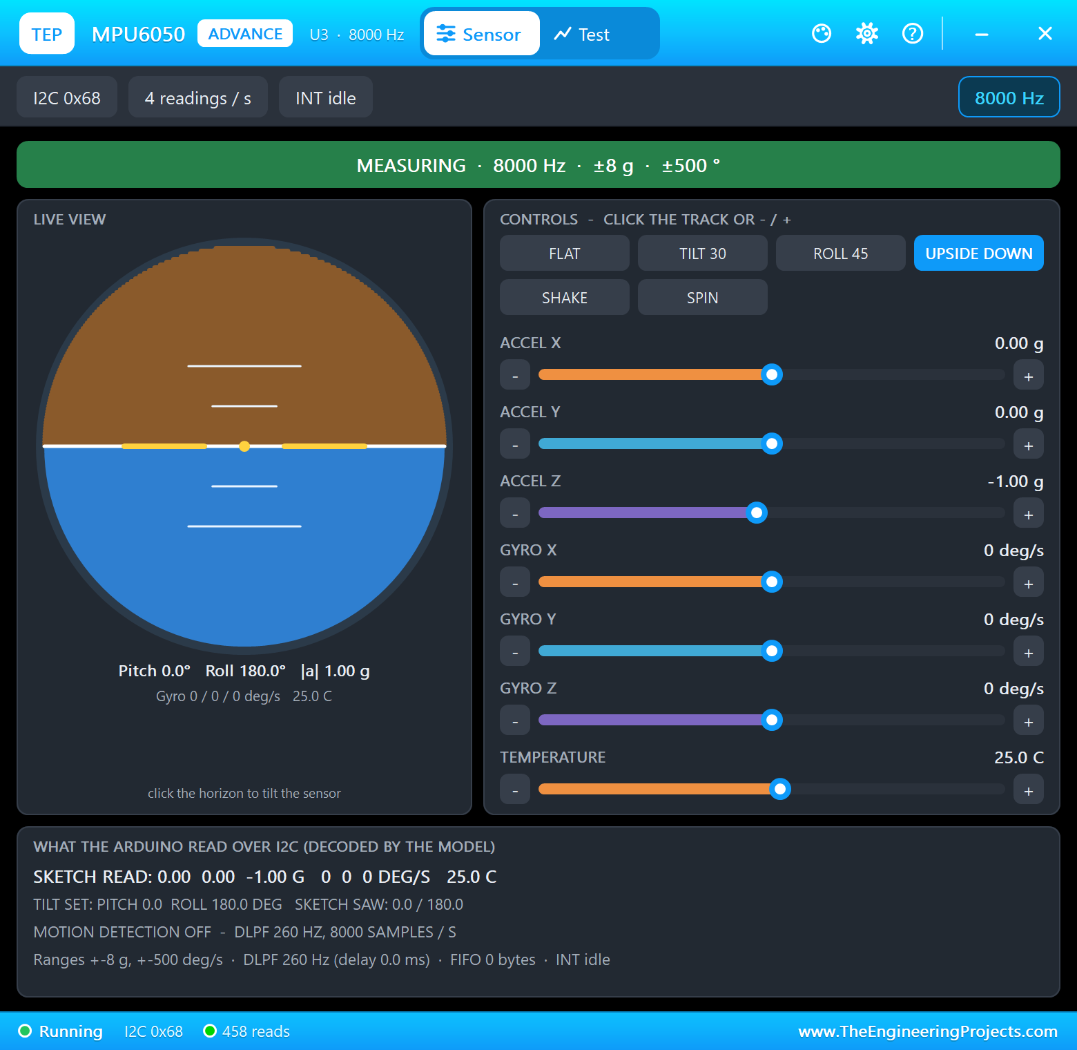
The NEO-6M and the MPU6050 are Advance models with pop-ups. The GPS pop-up shows the sky plot, the signal strength of every satellite and the position, and its scenario buttons set the place, the motion (Stop, Walk, Car) and the sky. The MPU6050 pop-up shows an artificial horizon and has presets: FLAT, TILT 30, ROLL 45, UPSIDE DOWN, SHAKE and SPIN.
Proteus Simulation of the GPS Tracker: the Circuit
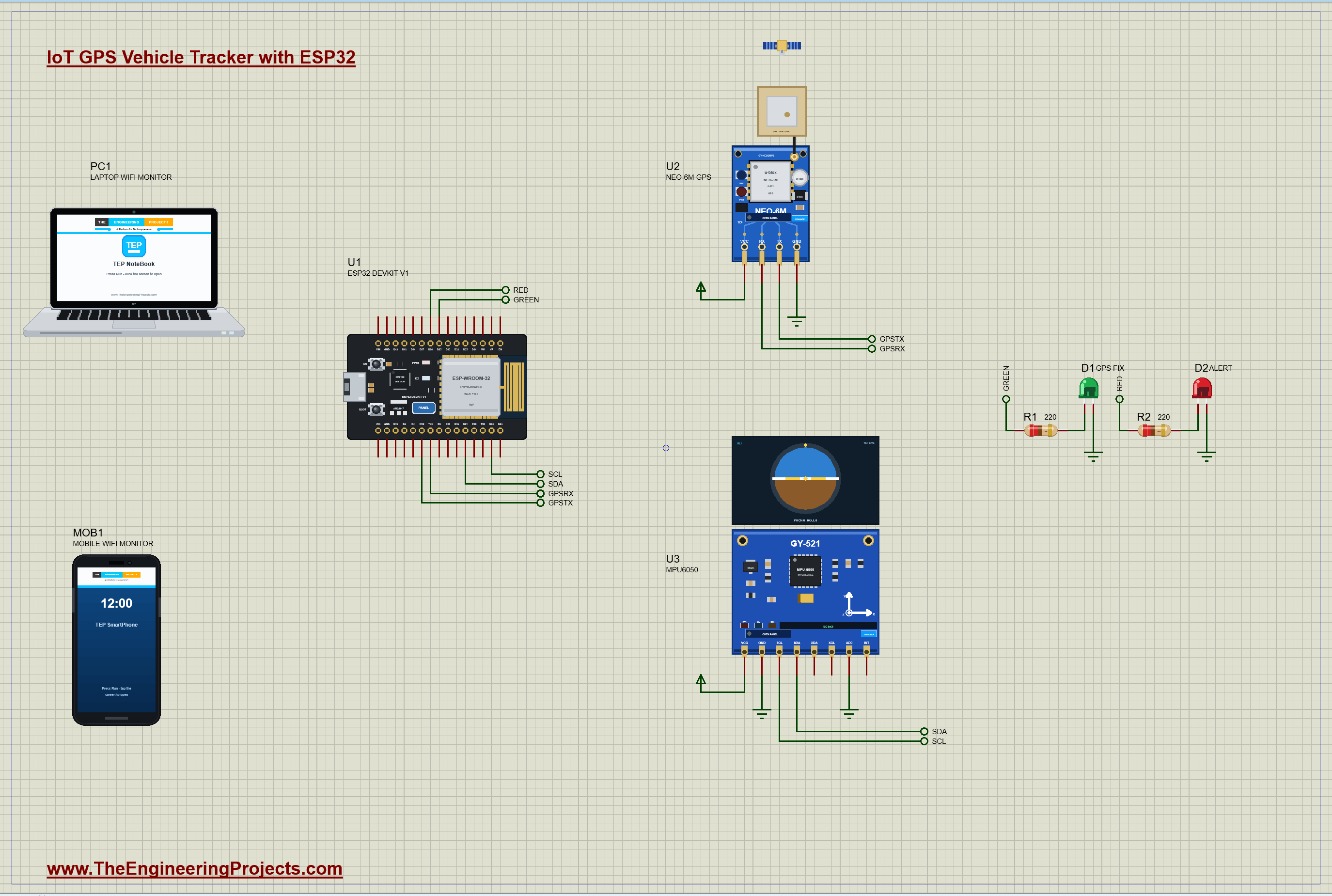
The GPS module talks over a serial port and the motion sensor over I2C, so they use different pins:
| ESP32 pin | Goes to | Why |
|---|---|---|
| RX2 (GPIO16) | the NEO-6M's TX | the NMEA sentences from the GPS, 9600 baud |
| TX2 (GPIO17) | the NEO-6M's RX | commands to the GPS (not used by the sketch, wired for completeness) |
| D21 / D22 | SDA / SCL of the MPU6050 | the I2C bus, address 0x68 with AD0 on ground |
| D25 | the green LED, through 220 ohm | searching (blinking) or a fix (steady) |
| D26 | the red LED, through 220 ohm | an alert |
Serial2 is the ESP32's second hardware UART, which keeps Serial, the USB serial port, free for the serial monitor. Both modules run from 5 V here: the GY-NEO6MV2 and GY-521 boards have their own 3.3 V regulators, so their signals are 3.3 V logic that suits the ESP32. The GPS's TX crosses to the ESP32's RX and the ESP32's TX to the GPS's RX: a serial link always crosses over.
How the GPS Vehicle Tracker Works
What a GPS Receiver Sends
A GPS receiver works out its position from the timing signals of four or more satellites, then reports it as NMEA sentences: lines of text that start with a dollar sign. The NEO-6M sends six of them once a second. The two that matter most are RMC (the recommended minimum: time, position, speed, course and date) and GGA (the fix: position, the number of satellites, the HDOP and the altitude). A cold start, with no stored almanac, takes a while: the module first has to find the satellites. In the simulation, the first fix comes 10 seconds after power-up; the real NEO-6M takes about 27 seconds with a clear sky.
TinyGPS++ Does the Parsing
Each byte from the GPS goes into TinyGPS++'s encode(). When a sentence is complete and its checksum is right, the library updates its fields: location, speed, course, altitude, satellites and hdop, each with isValid() and isUpdated(). It also has distanceBetween(), the distance between two points on the Earth by the haversine formula, which the sketch uses for the trip.
A Worked Example: Five Seconds of Driving
Take two positions five seconds apart from our run: 31.52434, 74.36394 and 31.52496, 74.36399. The latitude changed by 0.00062 degrees, and one degree of latitude is about 111,320 m, so the vehicle moved 69.0 m north. The longitude changed by 0.00005 degrees; a degree of longitude at this latitude is 111,320 m times cos(31.52 degrees), about 94,900 m, so that is 4.7 m east. Together, the square root of 69.0 squared plus 4.7 squared is 69.2 m in five seconds, or 13.8 m a second, almost exactly the 50 km/h the GPS reports. TinyGPS++'s distanceBetween() does the same sum on a sphere, which stays right over long distances too.
How Accurate Is a GPS?
A good consumer GPS like the NEO-6M is accurate to about 2.5 m with a clear view of the sky. Two numbers tell you how good a fix is. The number of satellites used: four is the minimum for a 3D fix, and more is better. The HDOP, the horizontal dilution of precision: it measures how well the satellites are spread across the sky, and below 1 is excellent, while above 5 the position is rough. Our run had 9 to 10 satellites and an HDOP of 0.9. In a city, buildings block the low satellites and reflect signals, so the HDOP rises and the position wanders; indoors, there may be no fix at all.
Detecting a Crash with an Accelerometer
An accelerometer at rest measures 1 g straight up: gravity. The MPU6050 gives the acceleration on three axes, so the total, the square root of x squared plus y squared plus z squared, is 1 g when the vehicle is still or cruising. A collision is a sudden jolt: the total jumps to several g for a moment, so the sketch calls anything over 2.5 g an IMPACT. A rollover is different: the total stays near 1 g, but its direction turns. The angle between the sensor's z axis and gravity is the tilt, 0 degrees upright and 180 degrees upside down; more than 60 degrees for a full second is a ROLLOVER. The one-second wait keeps a hard turn or a pothole from raising a false alarm.
Drawing the Route
Every 2 seconds the sketch stores the position as metres east and north of the first fix: one degree of latitude is about 111,320 m everywhere, and one degree of longitude is 111,320 m times the cosine of the latitude. Sixty points cover two minutes. For /track.bmp, the ESP32 scales those points to fit a 160 by 160 picture and draws them: the start green, the route cyan and the vehicle's last position red. Like the trend picture of our weather station, the BMP is sent a few rows at a time, and the sketch keeps reading the GPS between the rows so no sentence is lost.
Why draw the route on the ESP32 instead of using an online map? Because the tracker then works on any local network, with no Internet, no account and no map service. The picture is small, a few kilobytes, and any browser can show it. When the vehicle drives further than the picture shows, the scale grows by itself, so the whole route of the last two minutes always fits.
The ESP32 Code Explained
The whole sketch is included in the download. It uses the WiFi, WebServer and Wire libraries of the ESP32 core, TinyGPS++ and the Adafruit MPU6050 library. At the top are the limits of the alarms:
const float SPEED_LIMIT = 40;                            // km/h: faster is OVER SPEED
const float IMPACT_G = 2.5;                              // a jolt over 2.5 g is an impact (a crash)
const float ROLL_DEG = 60;                               // tilted more than 60 degrees for 1 s is a rollover
Reading the GPS
Serial2 starts at the GPS's 9600 baud on its fixed pins. Then every byte that has arrived goes to TinyGPS++; the loop calls this often, and so does the picture code between its rows:
Serial2.begin(9600, SERIAL_8N1, 16, 17); // the GPS: RX2 = GPIO16 (from its TX), TX2 = GPIO17 (to its RX)void feedGps() { while (Serial2.available()) gps.encode(Serial2.read()); }The Trip and the Speed Alarm
Each new position adds the distance from the last one to the trip, but only while moving: a parked GPS wanders by a few metres, and that wander would otherwise add up to a phantom trip. The speed alarm fires once when the limit is passed and is ready again when the speed drops 5 km/h below it:
if (havePrev && kmh > 3) tripM += TinyGPSPlus::distanceBetween(lastLat, lastLon, lat, lon); // (standing still adds no jitter) if (kmh > SPEED_LIMIT && !overSpeed) { overSpeed = true; alertNow("OVER SPEED " + String(kmh, 1) + " km/h"); }The Crash Alarm
Four times a second, the sketch reads the MPU6050 and works out the total acceleration in g and the tilt from upright:
  gNow = sqrt(ax * ax + ay * ay + az * az);
  tiltNow = gNow > 0.2 ? acos(constrain(az / gNow, -1.0, 1.0)) * 57.2958 : 0;   // 0 = upright, 180 = upside down
The Route Points and the LEDs
The route is kept in metres from the first fix, as 16-bit numbers to save memory:
  trackN[histAt] = (gps.location.lat() - lat0) * 111320.0;
  trackE[histAt] = (gps.location.lng() - lon0) * 111320.0 * cos(lat0 * DEG_TO_RAD);
digitalWrite(GREEN_LED, fix || (millis() / 500) % 2); // blinking: searching; steady: a fixThe dashboard shows the speed first, then its links, the position, the satellites and the HDOP, the trip, the motion and the alerts, newest first, each with the time and the place it happened. MAP opens the position in a map; it needs a real phone or computer with the Internet. NEW TRIP starts the distance, the top speed and the route again, and JSON gives everything to another device.
How to Run the Proteus Simulation
- Download the project zip below and install the library files (the steps are under the download button).
- Open ESP32-GPS-Tracker.pdsprj from the Proteus Simulation folder. Keep the HEX and DLL files next to it.
- Press Play. The green LED blinks while the GPS searches; after about 10 seconds it has a fix.
- Open the Laptop WiFi Monitor (PC1) or the Mobile WiFi Monitor (MOB1) and press Go.
- In the GPS pop-up, press Car: 50 km/h on a 500 m circle. Press Refresh on the page to follow the trip and the route.
- In the MPU6050 pop-up, press UPSIDE DOWN for a rollover, then FLAT. Press Stop in the GPS pop-up to end the drive.
Proteus Simulation Results
Here is one complete run of the simulation, with the numbers from our final test run. Every power-up of the NEO-6M is a cold start, so the dashboard first says it is searching, and the green LED blinks:
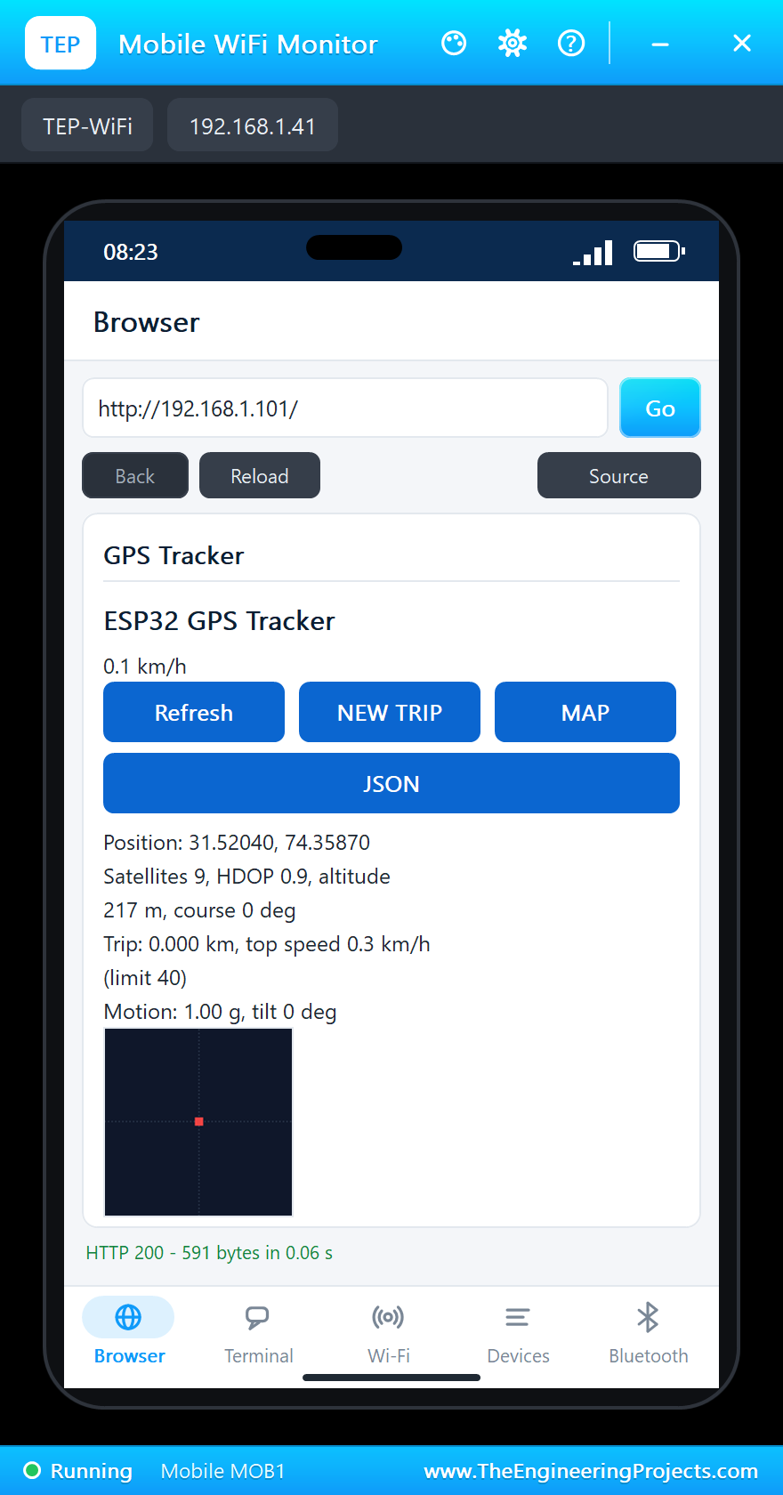
At 10.1 seconds of simulation the GPS had its fix: 31.52039, 74.35870, with 10 satellites, an HDOP of 0.9 and an altitude of about 217 m. The green LED stopped blinking and stayed on.
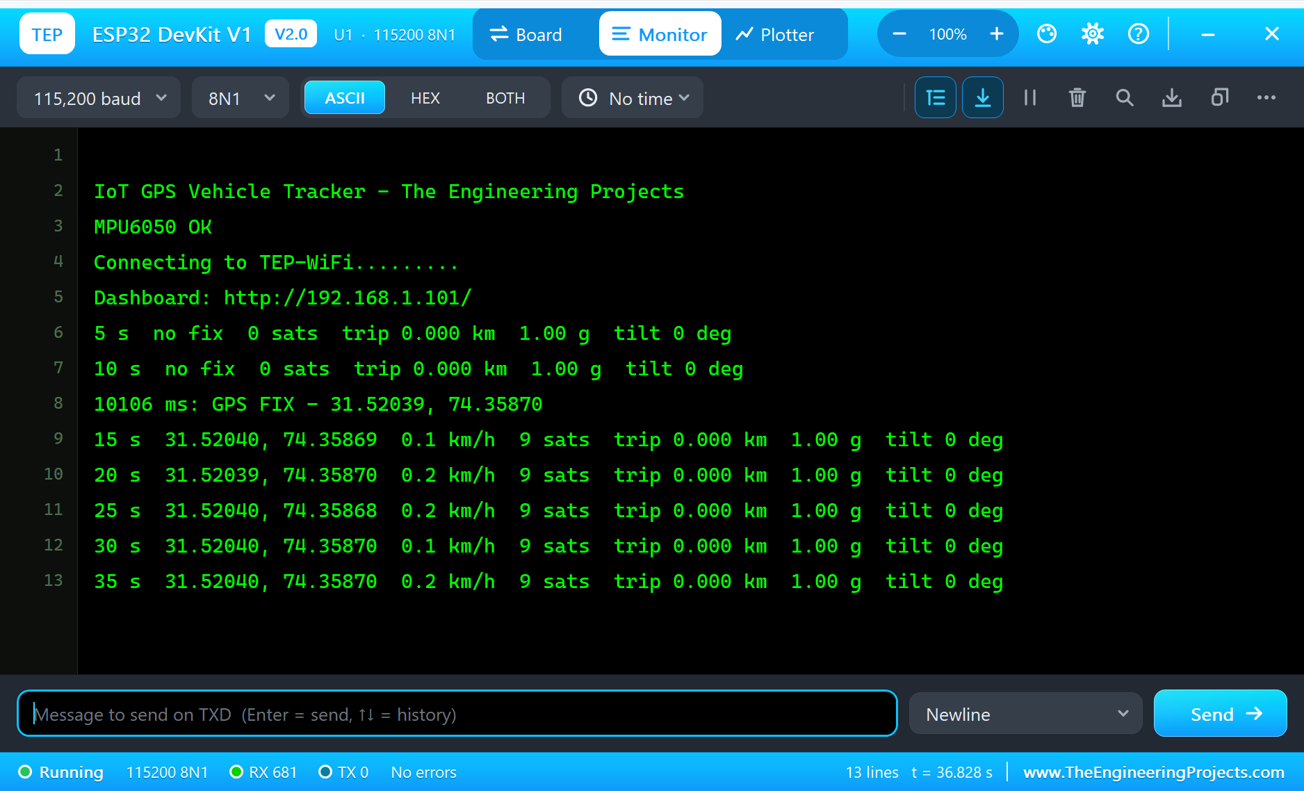
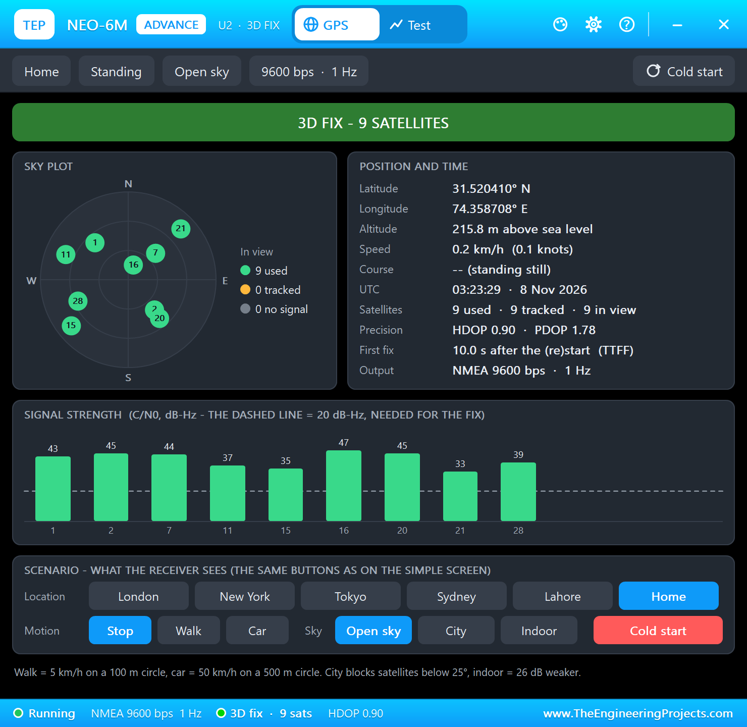
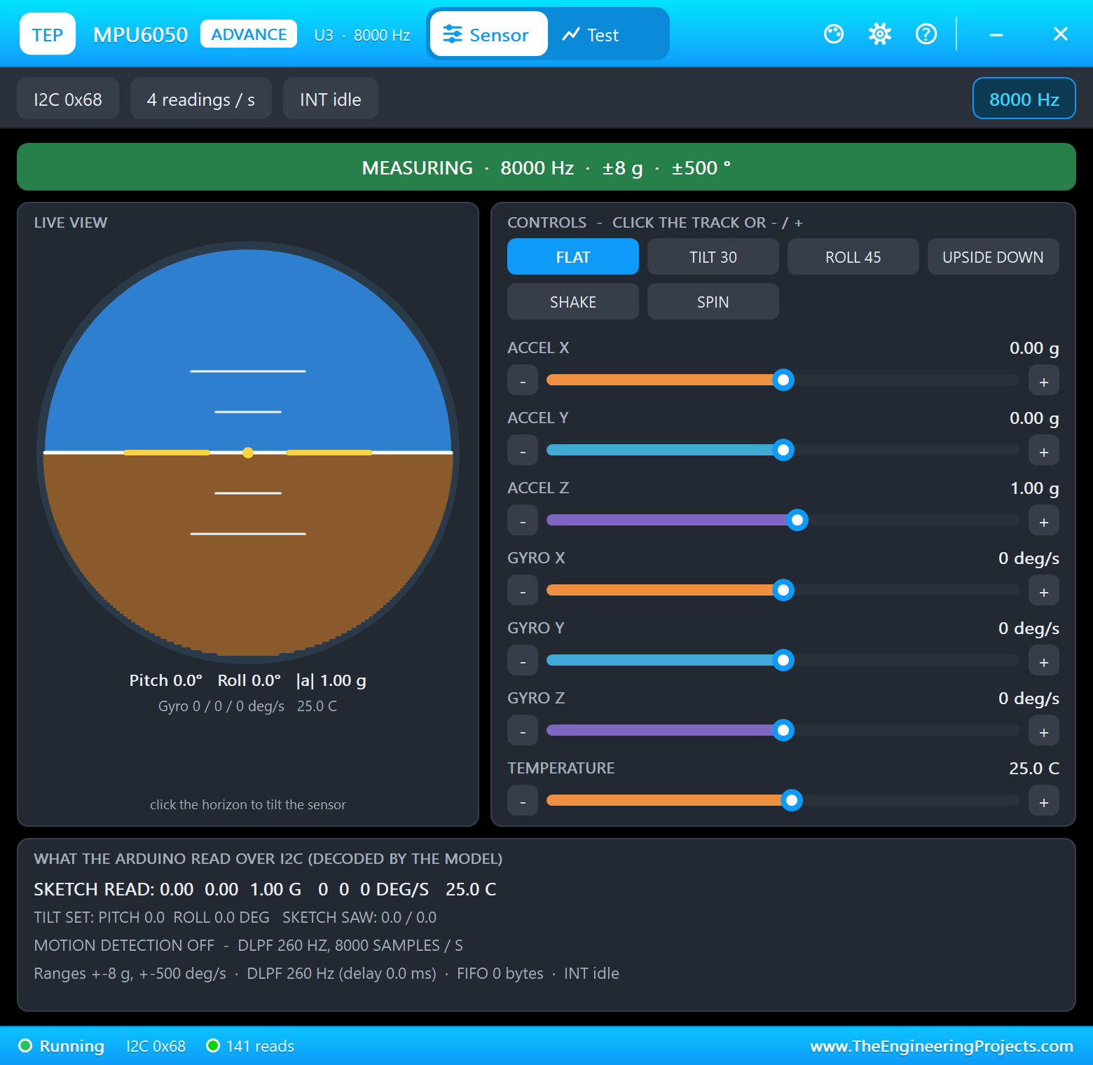
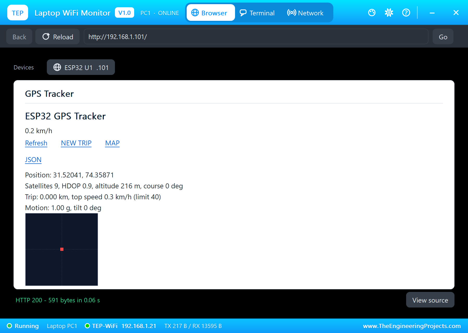
The GPS pop-up shows what the receiver sees: each satellite on the sky plot and its signal strength, all well above the 20 dB-Hz needed for a fix. Standing still, the speed reads 0.1 to 0.2 km/h, the small wander every real GPS has; the trip ignores anything under 3 km/h, so it stayed at 0.
On the Road
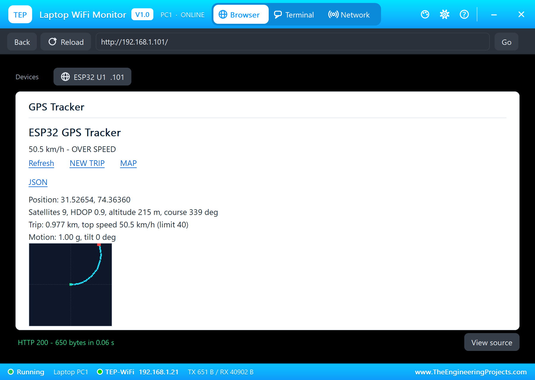
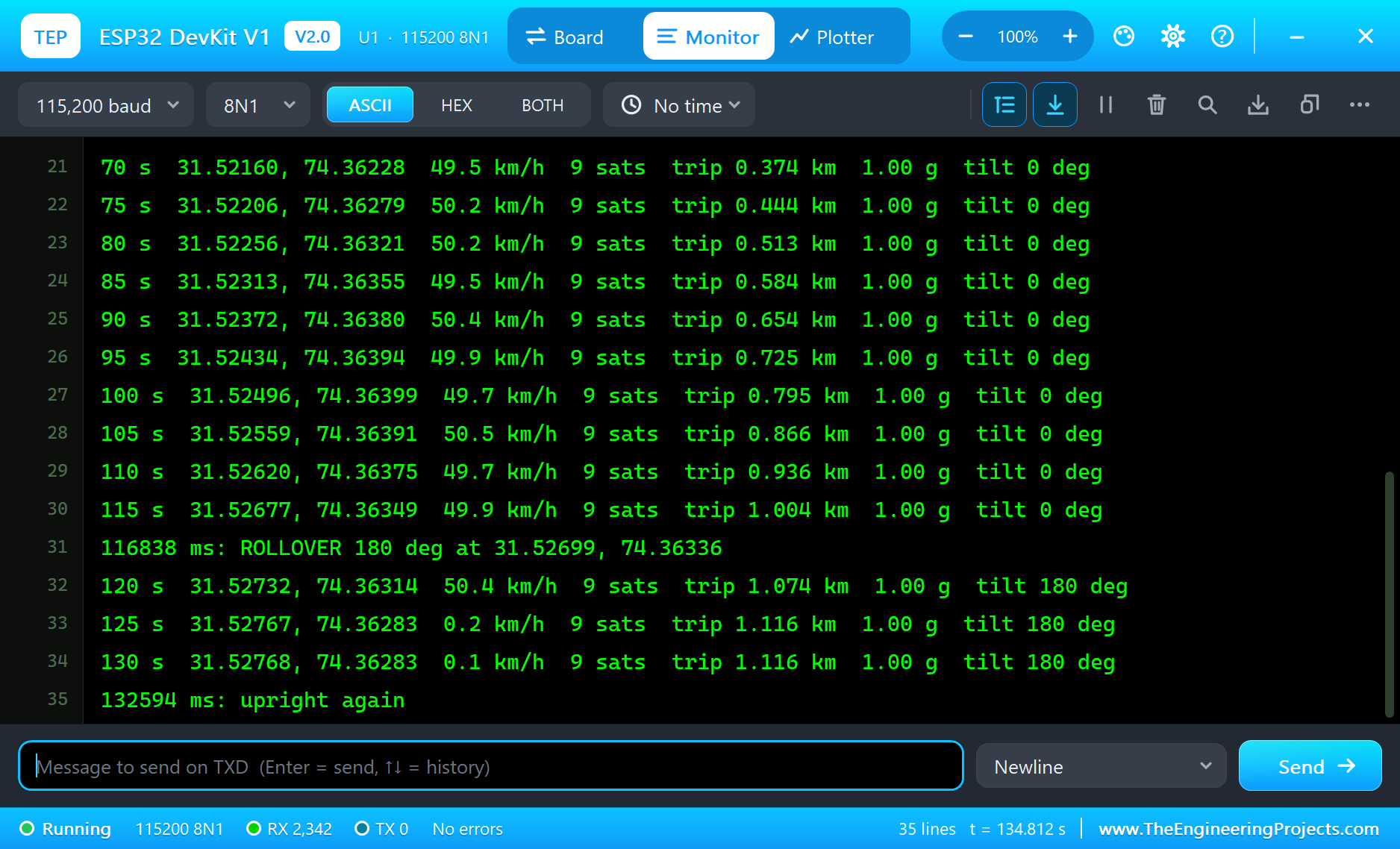
Car in the GPS pop-up: the vehicle drives at 50 km/h around a circle of 500 m radius. At 42.1 seconds the speed passed the 40 km/h limit and the tracker logged "OVER SPEED 50.4 km/h" with the place, and the red LED came on. The trip grew by about 70 m every 5 seconds, 13.9 m a second, which is exactly 50 km/h.
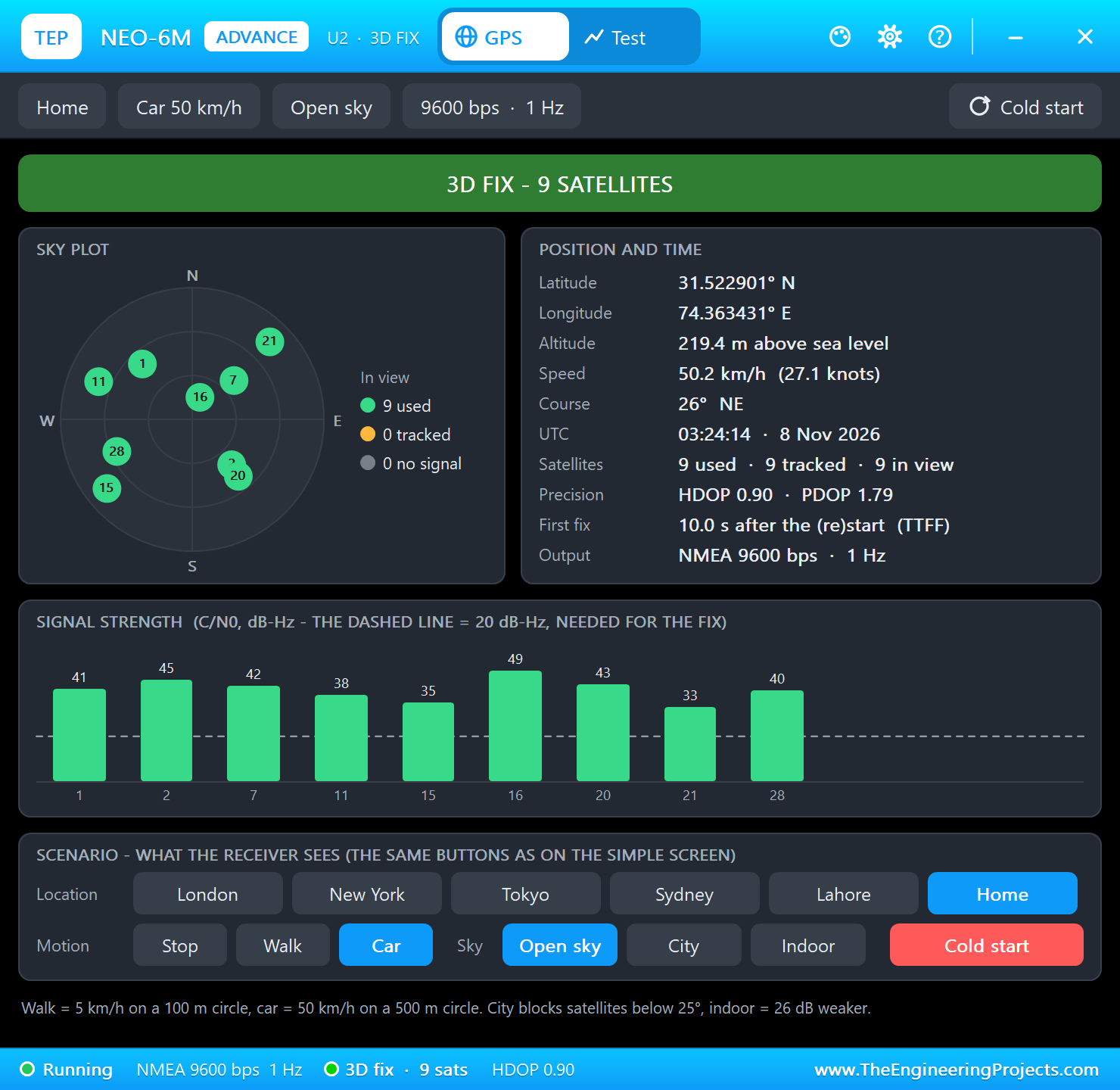
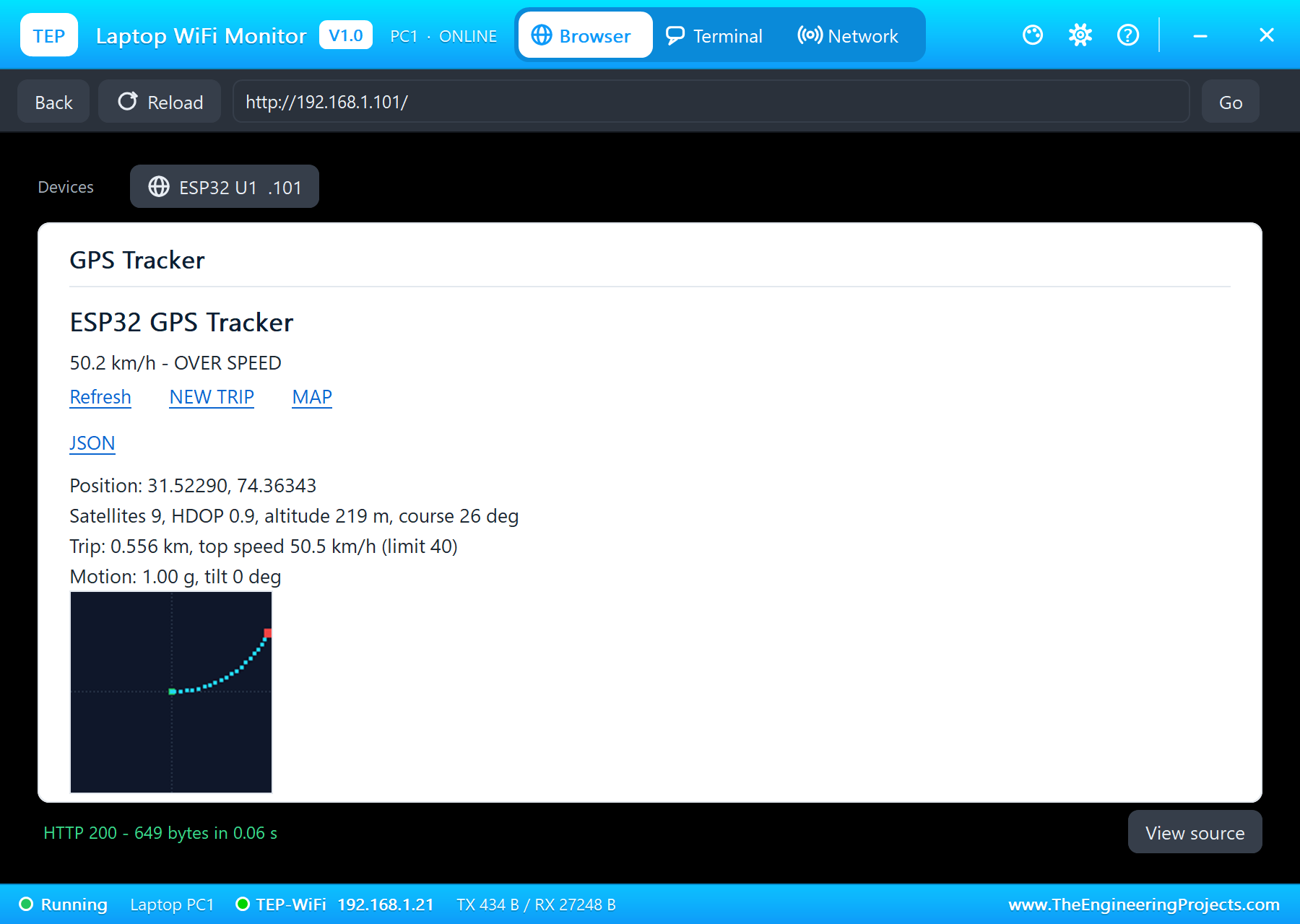
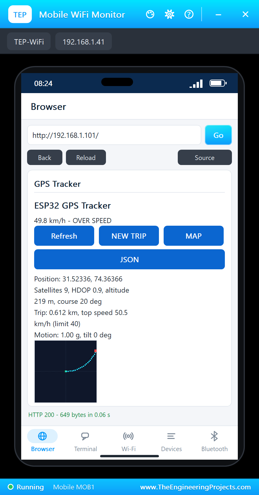
By 115 seconds the trip had passed 1.004 km with a top speed of 50.5 km/h, and the route picture showed the arc of the circle: the start in green at the middle, the route in cyan and the vehicle in red.
A Rollover
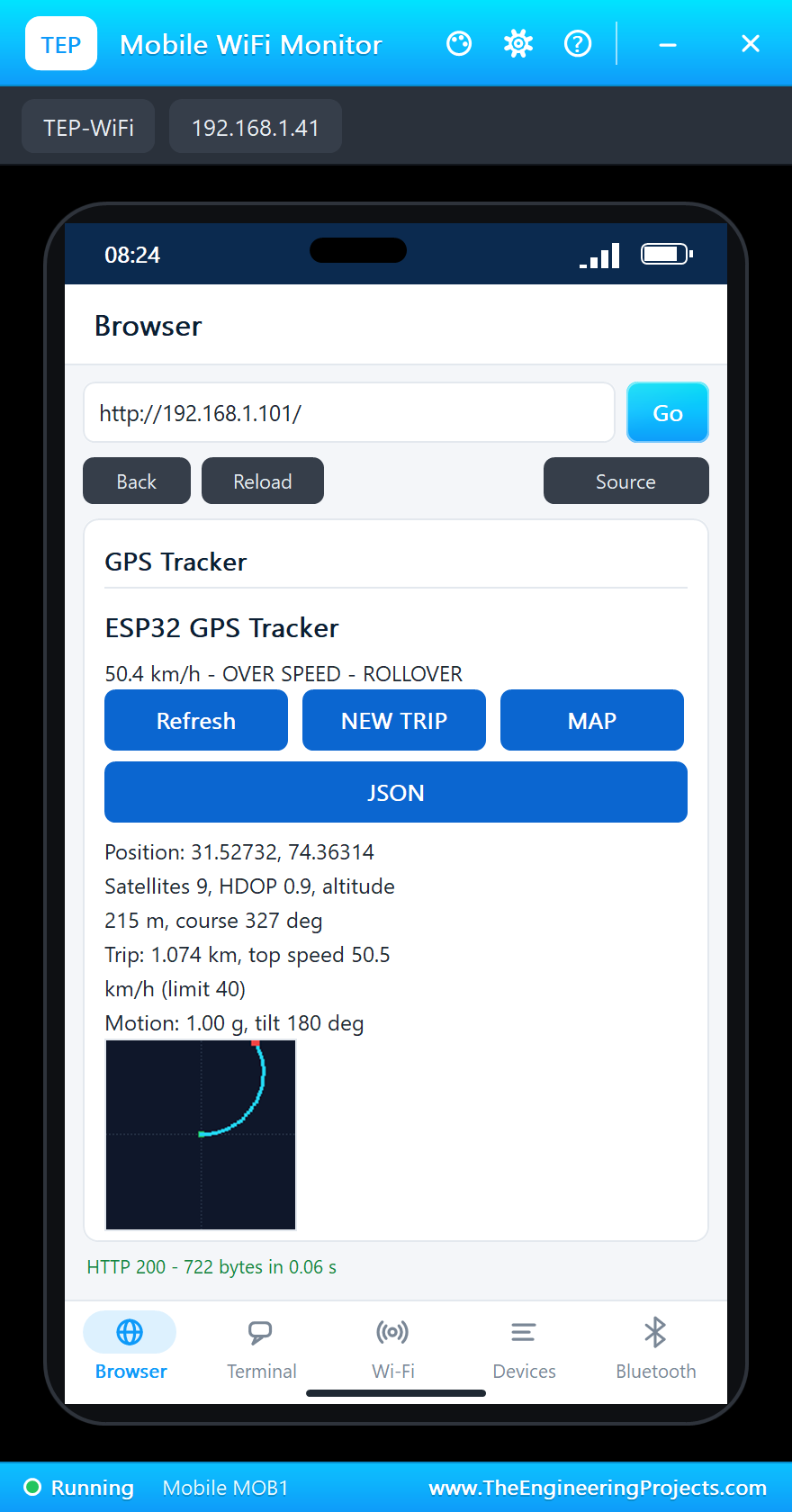
Then UPSIDE DOWN in the MPU6050 pop-up. The total acceleration stayed at 1.00 g, but its direction turned over: the tilt went to 180 degrees. After a full second, at 116.8 seconds, the tracker logged "ROLLOVER 180 deg at 31.52699, 74.36336": an alert with the exact place, the information a rescue service would need. The two simulation models are independent, so the GPS kept its circle until we stopped it.
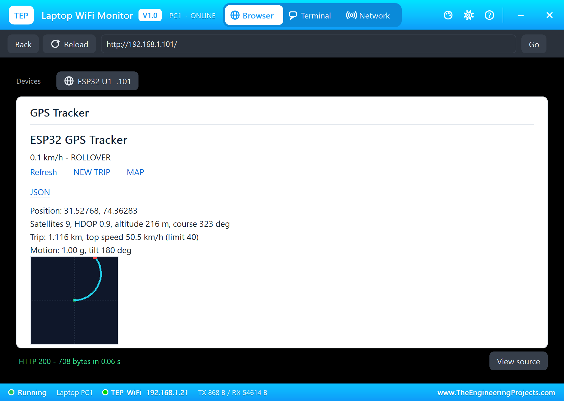
Stop in the GPS pop-up: the vehicle came to rest, the speed fell to 0.2 km/h and the trip stopped at 1.116 km. FLAT set the sensor upright again at 132.6 seconds.
| Moment | Reading | Result |
|---|---|---|
| Start | no fix, the green LED blinking | searching |
| 10.1 s | 31.52039, 74.35870, 10 satellites | the fix |
| 42.1 s, Car | 50.4 km/h | OVER SPEED, red LED |
| 115 s | trip 1.004 km, top 50.5 km/h | the route drawn |
| 116.8 s, UPSIDE DOWN | tilt 180 degrees | ROLLOVER with the position |
| Stop | trip 1.116 km | at rest |
Download the Project Files
Click the button below to download IoT-GPS-Vehicle-Tracker-ESP32-Proteus-Simulation-v1.0.zip (about 4.3 MB, without the source code of the models):
IoT GPS Vehicle Tracker with ESP32 - Proteus Simulation V1.0- Proteus Simulation: ESP32-GPS-Tracker.pdsprj, the firmware ESP32_GPS_Tracker.hex and copies of the models.
- Arduino Code: ESP32_GPS_Tracker.ino, the complete sketch.
- Proteus Library Files: the LIB files of the ESP32 DevKit V1, the NEO-6M, the MPU6050, the LEDs, the resistors and the two WiFi Monitors.
- Proteus Model Files: the DLL models, with
TEPNET.DLLfor the board and the Wi-Fi network. - README.txt: the installation steps, the properties, the test results, the links to every library post and the licences of the libraries in the HEX file.
No Proteus yet? Read How to Download and Install Proteus 7 and 8. New to libraries? Follow How to Install a New Library in Proteus.
How to Install the Project Files
- Close Proteus and extract the whole zip file, for example to your Desktop.
- Copy the files from Proteus Library Files into the LIBRARY folder of Proteus.
- Copy the files from Proteus Model Files into the MODELS folder.
- Start Proteus and open the project from the Proteus Simulation folder.
Changing the Code
The sketch builds with the TEP Boards for Proteus add-on for the Arduino IDE, which comes with our ESP32 DevKit V1 Library for Proteus, plus the TinyGPSPlus, Adafruit MPU6050, Adafruit BusIO and Adafruit Unified Sensor libraries from the Library Manager. Choose ESP32 DevKit V1 (TEP Proteus) as the board, export the compiled binary and set the ESP32's PROGRAM property to the new HEX file. The same sketch runs on a real ESP32 Dev Module. For another ESP32 project with I2C sensors and a web page, see our IoT Smart Energy Meter with ESP32.
Ideas to Extend the Project
- Send the position to a server or a phone by SMS with a SIM800L when an alert fires.
- Store the route on an SD card for a full trip log.
- Add a geofence: an alert when the vehicle leaves a set area.
- Measure fuel economy or driving style from the speed and the accelerations.
- Show the speed and the trip on an OLED for the driver.
- Put the tracker to sleep while parked and wake it on motion with the MPU6050's interrupt.
From Simulation to Real Hardware
- Give the antenna a view of the sky: a GPS indoors or under a metal roof may never get a fix.
- Expect a slower first fix: a real NEO-6M needs about 27 seconds cold, and a backup battery keeps later starts fast.
- Mount the MPU6050 firmly: it must move with the vehicle, level, or the tilt and the jolts will be wrong.
- Tune the thresholds: 2.5 g and 60 degrees are starting points; potholes and hard braking can come close.
- Power: a vehicle's 12 V needs a proper converter to 5 V; protect it from the spikes of the starter motor.
Troubleshooting
- Searching for satellites never ends: the GPS's TX is not on RX2 (GPIO16), or the sky is set to Indoor.
- "MPU6050 missing": SDA and SCL are swapped, or AD0 is high (the sketch asks for 0x68).
- The speed stays 0: the GPS's motion is Stop; press Car or Walk.
- A rollover alert at start: the MPU6050 is not FLAT.
- "Connecting to TEP-WiFi" never ends: the HEX file is missing beside the project, or
TEPNET.DLLis not in MODELS.
Limitations of the Simulation
- The GPS drives on the model's own circles (Walk: 100 m at 5 km/h, Car: 500 m at 50 km/h), not on real roads.
- The MPU6050's motion comes from its pop-up presets; a real crash is a short, sharp event.
- The map link needs a real phone or computer with the Internet; the simulated network has no maps.
- The ESP32 board runs at about half of real time on a typical PC; the times in this tutorial are simulation time.
- ESP32, NEO-6M (u-blox) and MPU6050 are names of their owners; this project is not made or endorsed by them or by Labcenter.
So, that was all about the IoT GPS Vehicle Tracker with ESP32 - Proteus Simulation. I hope it helps you build your own tracker: a GPS on Serial2, TinyGPS++, a crash alarm from an accelerometer and a route drawn by the ESP32, all tested in a simulation before it goes into a vehicle. More IoT projects with the ESP32 and the Raspberry Pi 5 are coming in this series. If you have any questions, ask in the comments and I will help you out. Till the next tutorial, take care and have fun!