The Internet of Things ( or IoT) is a network of interconnected computing devices such as digital machines, automobiles with built-in sensors, or humans with unique identifiers and the ability to communicate data over a network without human intervention.
Hello readers, I hope you all are doing great. In this tutorial, we will learn how to send sensor readings from ESP32 to the ThingSpeak cloud. Here we will use the ESP32’s internal sensor like hall-effect sensor and temperature sensor to observe the data and then will share that data cloud.
What is ThingSpeak?
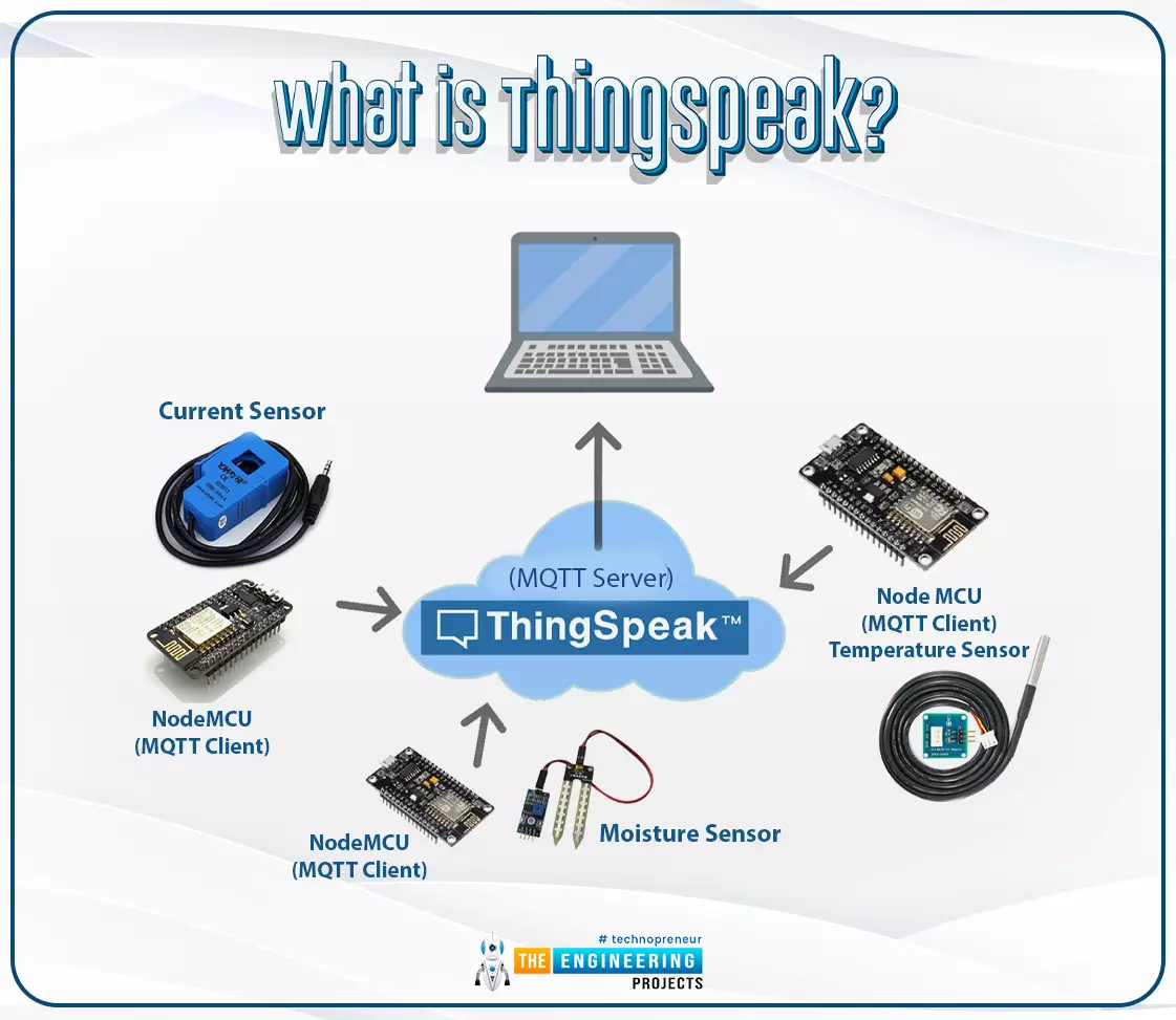
Fig. 1: ESP32 ThingSpeak
It is an open data platform for IoT (Internet of Things). ThingSpeak is a web service operated by MathWorks where we can send sensor readings/data to the cloud. We ...
Hello readers, I hope you all are doing great. In this tutorial, we will learn about the ESP-NOW protocol and how to communicate data between two ESP modules through ESP-NOW protocol and that is too without Wi-Fi connectivity.
What is ESP-NOW Protocol?
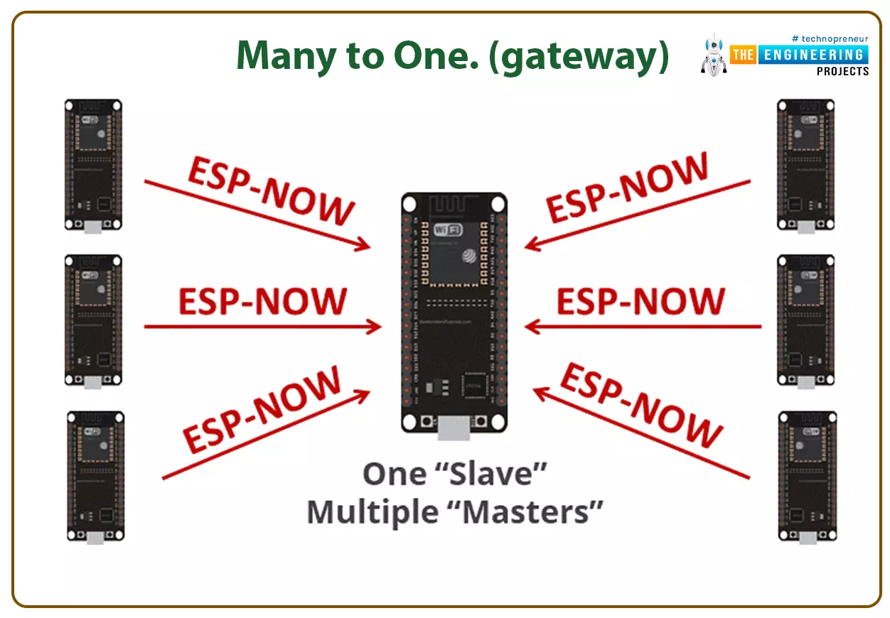
Fig. 1: ESP-NOW Protocol
ESP–NOW is a connectionless communication protocol that is used for sharing small data packets between two ESP boards. This protocol is developed by Espressif.
Features of ESP-NOW Protocol:
It is a low-power wireless protocol, which makes two or more ESP devices communicate directly with each other without using Wi-Fi.
ESP-NOW protocol does not require a handshake for establishing a connection but, they require pairing and once the devices are paired they can exchang ...
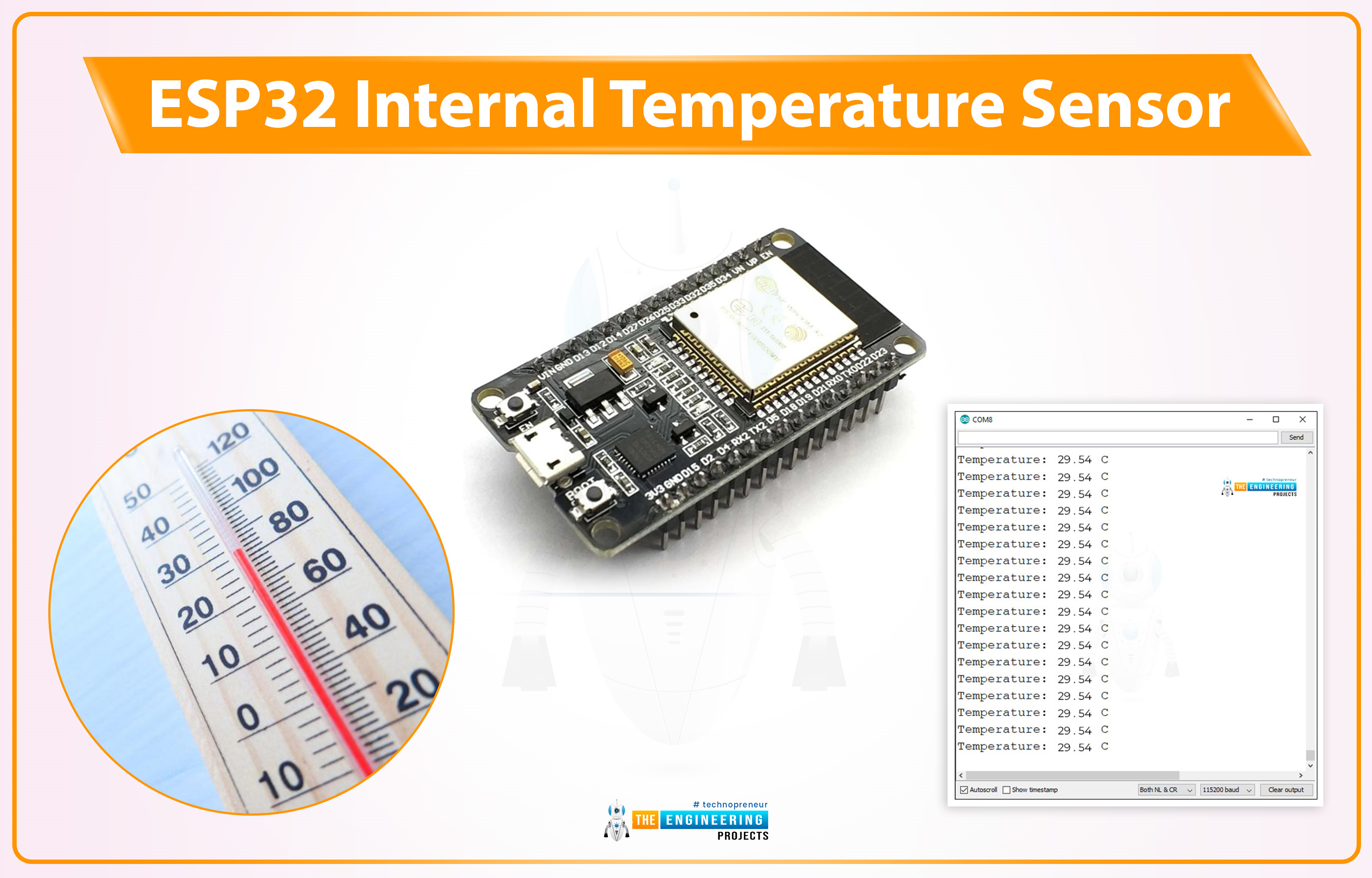
Hello friends, I hope you all are doing great. Welcome to the 3rd lecture of Section 5(ESP32 Sensors) in the ESP32 Programming Series. We have already discussed the two built-in ESP32 sensors i.e. Hall Effect Sensor and Capacitive Touch Sensor. Today, we are going to discuss the 3rd and final built-in ESP32 sensor i.e. Internal Temperature Sensor.
ESP32 Internal Temperature Sensor is used to calculate the temperature of the ESP32 core. So, we can't use it to measure the ambient temperature (the temperature of the atmosphere), for that, we need to use embedded temperature sensors i.e. DS18B20, DHT11, BMP280 etc. We will first discuss the basics of this Internal Temperature Sensor and then will design a code to monitor the change in temperature by changing the frequency of the ESP32 CPU.
...
Hello readers, I hope you all are doing great. In our previous tutorial, we learned SMTP server and how to implement an SMTP server for sending emails with ESP32. In the previous tutorial, we also demonstrated some examples like sharing raw text, HTML text, images and text files.
So, at the transmitter end, we are using the SMTP server.
But, what about the receiver end?
At the receiver end, we use another protocol called IMAP (or Internet Message Access Protocol) and POP3 (Post office Protocol V3) for receiving the emails.
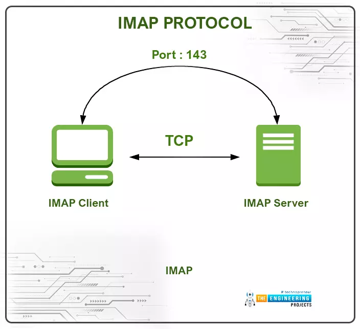
Fig. IMAP and SMTP
What is IMAP Protocol and How does it Work?
IMAP is an application layer (TCP/IP) protocol that is used at the receiver end to receive emails from SMTP server or mail server. IMAP follows the client/server mo ...
Hello readers, I hope you all are doing great. In this tutorial, we will learn how to send an email using ESP32 module. We will also learn to send text files, images or some sensor readings using the SMTP server using the ESP32 module.
In IoT (Internet of things), there are various applications where we need to send emails carrying information like sending some sensor readings, altering emails, images, text files and much more.
What is SMTP?
SMTP or simple mail transfer protocol is an internet standard for sending and receiving electronic mail (or email) where an SMTP server receives emails from the email client.
SMTP is also used for setting communication between servers.
Various email providers like Gmail, Hotmail, Yahoo, etc. have unique SMTP ...
Hello readers, I hope you are all doing great. Welcome to the 2nd lecture of Section 5(ESP32 Sensors) in the ESP32 Programming Series. In the previous tutorial, we discussed the built-in ESP32 Hall Effect Sensor. In this tutorial, we will discuss another inbuilt sensor of the ESP32 i.e. Capacitive Touch Sensor.
ESP32 Board has 10 built-in capacitive touch pins, which generate an electrical signal when someone touches these pins. These ESP32 touch pins are normally used to wake up the board from deep sleep mode. These touch pins are also used to replace the normal mechanical buttons with touch pads, improving the presentation of the IoT projects.
Here's the video demonstration of the ESP32 Capacitive Touch Sensor:
Before going forward, let's first understand how this touch sens ...
Hello readers, I hope you all are doing great. Welcome to Section 5 of the ESP32 Programming Series. In this section, we are going to interface different Embedded Sensors with the ESP32 Microcontroller Board. ESP32 development board is featured with some inbuilt sensors(i.e. hall effect sensor, capacitive touch sensor) so, in the initial tutorials of this section, we will explore these built-in ESP32 sensors and in the later lectures, we will interface third-party sensors with the ESP32.
In today's lecture, we will discuss the working/operation of the ESP32 built-in Hall Effect Sensor. Hall Effect sensor is used to detect the variation in the magnetic field of its surroundings. So, let's first understand What's Hall Effect:
What is the Hall Effect?
The Hall Effect phenomenon was fir ...
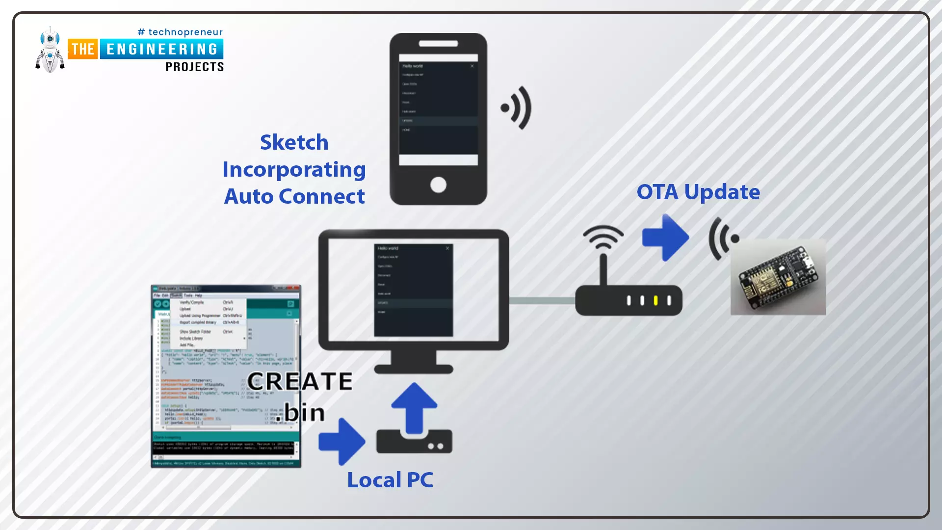
Hello readers, I hope you are all doing great. In this tutorial, we are going to discuss the OTA web updater on the ESP32.
We already covered the fundamentals of OTA programming in ESP32, in our previous tutorial where we used the Arduino IDE to upload OTA code into the ESP32 module using the network port.
In the OTA web updater, you need to create a web server page for OTA programming.
[caption id="attachment_166886" align="aligncenter" width="1920"]
ESP32 OTA web updater[/caption]
Fig.1 ESP32 OTA web updater
Over the Air Web Updater
"Over-the-air" refers to the ability to wirelessly download an application, configuration, or firmware to internet-enabled devices, also known as IoT. (OTA). It functions similarly to our computers, laptops, tab ...
Hello readers, hope you all are doing great. In this tutorial, we are going to discuss a mechanism that allows users to update the ESP32 with a new program wirelessly or over the air (without using a USB cable to upload a new program).
Over-The-Air (OTA) programming
Fig. 1 ESP32 OTA
OTA programming is the mean by which a product manufacturer or product service provider can update the features or functionality of the device wirelessly or over the air, after the device has been deployed in the field where connecting a cable or uploading the code serially is difficult.
One key advantage of OTA is that a single central node can send an update to multiple ESPs on the same network.
The device must have a provisioning client capable of receivin ...
Hello readers, hope you all are doing great. In this tutorial, we will discuss low power modes in ESP32, their purpose and their implementation to increase the battery life by reducing power consumption.
Purpose of Low Power Modes
Fig.1
Along with multiple wireless and processing features, ESP32 also provides us with a power-saving feature by offering sleep modes. When you are powering the ESP32 module from the live supply using an adaptor or a USB cable, there is nothing to worry about power consumption. But when you are using a battery, as a power source to ESP32, you need to manage the power consumption for longer battery life.
Low Power Modes in ESP32
When ESP32 is in sleep mode, a small amount of power is required to maintain the state of ...