Hello friends! Today we will connect two nRF24L01 radio modules to two Arduino boards and send a small command from one board to the other. We will start with the radio interface and wiring, install the RF24 library, and then use one complete sketch with a selectable transmitter or receiver role.
The useful part of this project is not simply making a number appear in Serial Monitor. We also want to understand which settings must match, what an acknowledgment proves and how to distinguish an SPI connection problem from a wireless communication problem. Those distinctions make the same hardware much easier to use in a sensor node or remote-control experiment.
The examples below target two Uno R3 boards and ordinary nRF24L01+ modules. The original wiring illustrations, demonstration video and library archive remain available. The revised code uses the maintained RF24 interface and explicit packet bytes, so it does not depend on both processors storing an unsigned long in the same format.
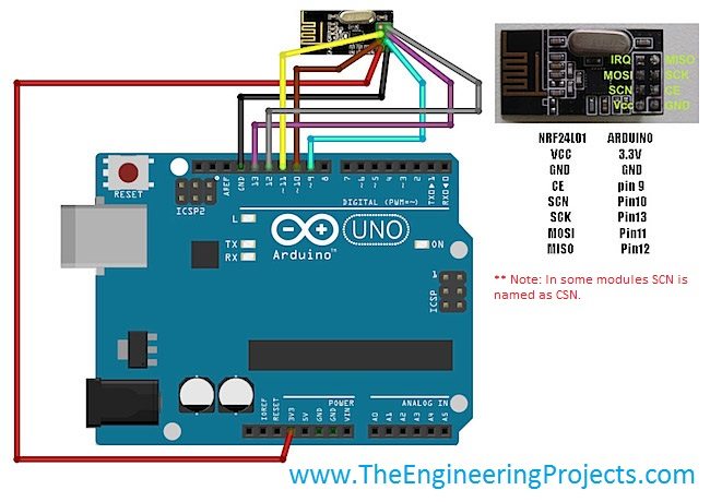
Understand the nRF24L01 Radio
The nRF24L01 family provides a small 2.4 GHz packet radio controlled through SPI. It is a transceiver, meaning it can both transmit and receive. However, one radio operates in one direction at a time; it does not transmit and receive simultaneously. Automatic acknowledgment works by switching direction during the packet exchange.
The nRF24L01+ supports air rates of 250 kbit/s, 1 Mbit/s and 2 Mbit/s. The earlier non-plus device does not support the 250 kbit/s mode. Packet payloads can contain up to 32 bytes. These figures refer to radio capabilities, not a promise that an application transfers user data at the raw air rate. Nordic's nRF24L01+ product specification provides the underlying limits.
For this tutorial, both nodes use 1 Mbit/s and a fixed four-byte payload. That keeps the experiment simple and avoids relying on dynamic-payload configuration. Small commands and sensor readings fit comfortably into this format; larger records need an application protocol that splits and reassembles them.
If the module is new to you, our introduction to nRF24L01 gives additional background. For another wireless approach, see Introduction to XBee and XBee Arduino Interfacing. Their configuration methods are different, so do not mix their wiring or command instructions.
Parts and Power Requirements
Prepare two Uno R3 boards, two compatible radio modules, short jumper wires and USB connections for programming. Each radio needs a stable supply appropriate to its module. A bare nRF24L01+ supply must remain within 1.9–3.6 V; a nominal 3.3 V regulated supply is the usual choice. Do not connect its VCC pin to the Uno's 5 V output.
Some adapter boards accept a different input voltage because they include a regulator. That rating belongs to the adapter, not to the radio chip. Read the board markings and documentation before deciding where to connect power.
Place supply decoupling near the module. A local ceramic bypass capacitor and, where appropriate, a small bulk capacitor help with transient current, but they cannot compensate for an undersized regulator or a badly connected ground. PA/LNA modules with external antennas can require substantially more current than the small PCB-antenna modules used for a first experiment.
For a bench setup, choose a regulator with adequate transient margin and keep the supply leads short. If communication fails only during transmission, measure the supply at the radio rather than assuming that a steady multimeter reading at the Arduino proves the radio rail is stable.
Connect the Radio to Arduino Uno
The SPI controller is the Arduino in this arrangement. MOSI carries commands and data from Arduino to the radio; MISO carries radio data back to Arduino. SCK is a clock waveform during a transaction, not simply a permanent enable level.
| Radio signal | Uno connection | Function |
|---|---|---|
| VCC | Suitable regulated 3.3 V supply | Radio power |
| GND | Arduino and supply ground | Shared reference |
| CE | Digital 9 | Radio operating control used by the library |
| CSN | Digital 10 | Active-low SPI chip select |
| SCK | Digital 13 | SPI clock |
| MOSI | Digital 11 | Arduino data output to the radio |
| MISO | Digital 12 | Radio data output to Arduino |
| IRQ | Unconnected in this example | Optional interrupt indication |
Check the connector orientation on your actual module. A pin diagram viewed from the component side can be misleading if you are looking at the solder side. Follow signal names and continuity, not an assumed left-to-right order.
The genuine radio's digital input specifications permit interfaces that its supply pin does not. Nevertheless, verify logic compatibility for the exact module or clone rather than assuming every 3.3 V product has 5 V tolerant inputs. A required level shifter must support the SPI signal directions and speed.
The receiver uses the same wiring:
CE and CSN are ordinary configurable control pins in the RF24 constructor, while the SPI pins belong to the board's SPI peripheral. On a different Arduino model, do not copy the Uno's SPI pin numbers without checking the board pinout. The constructor RF24 radio(9, 10) does not move MOSI, MISO or SCK to arbitrary pins.
Install the RF24 Library
Use Arduino IDE's Library Manager to find RF24 maintained by the nRF24 project, and note the installed version. Its official repository contains the library source and examples. Avoid leaving several competing RF24 folders in the library search path, because the IDE may compile against a different copy from the one you intended.
The original download is retained for readers reproducing the historical tutorial:
That archive is a historical attachment, not a claim that it is the current maintained release. Use the maintained library for the revised sketch. If an API error occurs, first inspect the library name and version reported by the build output instead of randomly changing the radio settings.
SPI is supplied by the Arduino board core, so it does not require an unrelated third-party download for the Uno. The radio library then uses SPI to read and write the transceiver's configuration registers.
Define a Small Packet Before Writing the Program
Our packet contains four bytes: a format version, a command and a 16-bit sequence number stored least significant byte first. The command remains one in this demonstration, matching the original project's simple transmitted value. The sequence changes so we can see that new packets are being handled.
| Byte position | Meaning | Example |
|---|---|---|
| 0 | Packet format version | 1 |
| 1 | Command value | 1 |
| 2 | Sequence low byte | 44 for sequence 300 |
| 3 | Sequence high byte | 1 for sequence 300 |
The receiver reconstructs the sequence as low byte + 256 × high byte. For the example, 44 + 256 × 1 = 300. This explicit encoding avoids structure padding and processor-specific integer widths. It also gives us a defined place to reject an unsupported packet version.
The five-byte radio address selects the receiving pipe. It is not a network login, an encryption key or proof of the sender's identity. Anybody implementing a suitable compatible radio configuration may be able to transmit to that address.
Arduino Transmitter and Receiver Sketch
Upload the following sketch to both boards. Set TRANSMITTER to true on the sending board and false on the receiving board. Keep all shared radio settings identical. Open each Serial Monitor at 57600 baud; the serial rate is independent of the radio's air rate.
#include <SPI.h>
#include <RF24.h>

constexpr bool TRANSMITTER = true; // false on the receiver
constexpr byte CE_PIN = 9;
constexpr byte CSN_PIN = 10;
constexpr byte PACKET_SIZE = 4;
const byte ADDRESS[6] = "TEP01";
RF24 radio(CE_PIN, CSN_PIN);

unsigned long lastSentAt = 0;
uint16_t nextSequence = 0;

void setup() {
  Serial.begin(57600);
  if (!radio.begin()) {
    Serial.println(F("Radio not responding over SPI. Check wiring and power."));
    while (true) { delay(1000); }
  }
  radio.setAddressWidth(5);
  radio.setChannel(76);
  if (!radio.setDataRate(RF24_1MBPS)) {
    Serial.println(F("Unable to select the requested data rate."));
    while (true) { delay(1000); }
  }
  radio.setPALevel(RF24_PA_LOW);
  radio.setCRCLength(RF24_CRC_16);
  radio.setAutoAck(true);
  radio.setRetries(5, 5);
  radio.disableDynamicPayloads();
  radio.setPayloadSize(PACKET_SIZE);

  if (TRANSMITTER) {
    radio.openWritingPipe(ADDRESS);
    radio.stopListening();
    Serial.println(F("Transmitter ready."));
  } else {
    radio.openReadingPipe(1, ADDRESS);
    radio.startListening();
    Serial.println(F("Receiver ready."));
  }
}

void loop() {
  if (TRANSMITTER) {
    const unsigned long now = millis();
    if (now - lastSentAt < 1000UL) return;
    lastSentAt = now;
    const uint16_t sequence = nextSequence++;
    const byte packet[PACKET_SIZE] = {
      1, 1, byte(sequence & 0xFF), byte(sequence >> 8)
    };
    const bool acknowledged = radio.write(packet, sizeof(packet));
    Serial.print(F("Sequence "));
    Serial.print(sequence);
    Serial.println(acknowledged ? F(" acknowledged") : F(" no acknowledgment"));
  } else {
    while (radio.available()) {
      byte packet[PACKET_SIZE];
      radio.read(packet, sizeof(packet));
      if (packet[0] != 1) {
        Serial.println(F("Unsupported packet version."));
        continue;
      }
      const uint16_t sequence = uint16_t(packet[2]) |
                                (uint16_t(packet[3]) << 8);
      Serial.print(F("Command="));
      Serial.print(packet[1]);
      Serial.print(F(" sequence="));
      Serial.println(sequence);
    }
  }
}
What the Configuration Does
begin checks whether the local controller can communicate with its radio over SPI. A failure at that point is not a missing wireless acknowledgment. Correct local wiring and power before moving on to address or channel troubleshooting.
The example fixes the address width, channel, data rate, CRC length and payload size. Channel 76 corresponds to 2476 MHz under the device's channel mapping. Select channels and power settings appropriate to your hardware and location; the chip's complete tuning range should not be treated as permission to transmit anywhere it can tune.
The transmitter opens a writing pipe and stops listening. The receiver opens reading pipe 1 and starts listening. Automatic acknowledgment supplies the return radio response without requiring the receiver's Arduino sketch to call write for each packet. The RF24 class reference documents these operations and their configuration requirements.
The receiving loop drains available packets rather than handling only one and immediately waiting. At the low demonstration rate this is straightforward; at higher rates, excessive serial printing can become the bottleneck. The radio has limited FIFO storage, so slow application processing can eventually lose incoming traffic.
Test the Link in Stages
- Power and inspect each node independently.
- Confirm that both boards pass the local radio initialization step.
- Upload the receiver role to one board and the transmitter role to the other.
- Place the modules a sensible distance apart on the bench rather than pressing the antennas together.
- Observe incrementing sequence numbers at the receiver and acknowledgment reports at the transmitter.
- Turn off the receiver and observe that acknowledgments stop.
- Restore receiver power and check that communication resumes after its startup.
The historical Serial Monitor screenshot shows the earlier example receiving a repeated command value:
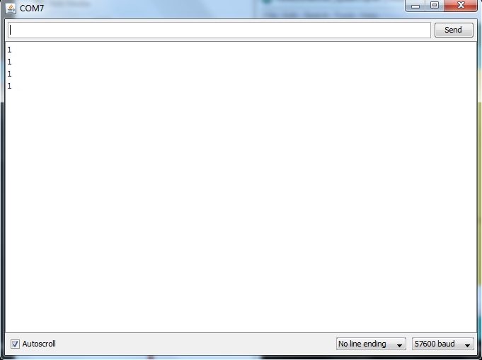
The revised sketch prints a command and sequence instead, so do not expect its lines to match that screenshot exactly. These are reader-run checks; the retained screenshot and video are historical demonstrations, not evidence of a fresh hardware run of the revised code.
Acknowledgments, Retries and Timing
With auto-acknowledgment enabled, a successful write indicates that the transmitter received the expected radio acknowledgment. It does not prove that the receiver's Arduino has validated the command or completed an external action. The radio may acknowledge a packet before the application reads it.
A failed write also does not prove that the receiver never obtained the packet. The data might arrive while its return acknowledgment is lost. Therefore, blindly retrying a command such as “advance motor one step” can cause unintended repeated actions. For control work, include a command identifier and an application response with clearly defined completion meaning.
setRetries(5, 5) configures the retry timing and maximum retry count according to the library's encoding. The delay field represents 250-microsecond steps with an offset, so a value of five corresponds to 1500 microseconds between retries. It does not request a five-second delay.
Our one-second transmission interval is deliberately slow for observation. The four payload bytes contain 32 bits, which alone occupy 32 microseconds at 1 Mbit/s. Actual airtime is longer because the packet also includes addressing, control and error-checking information. Turnaround, acknowledgment and retries further increase transaction time.
The millis scheduling avoids a deliberate one-second blocking delay, but radio.write itself waits for its configured transaction to finish. If your application needs tighter response guarantees, measure that worst-case blocking interval and select an appropriate library transmission method and state machine.
Fix Common Communication Problems
| Symptom | Investigate first | Reason |
|---|---|---|
| begin fails | VCC, ground, SPI wiring and CSN | The Arduino cannot communicate with its local radio |
| Initialization succeeds but no acknowledgments | Receiver listening state and matching configuration | Local SPI success does not establish an RF link |
| Works intermittently | Supply transients, interference and antenna placement | Packet reception depends on electrical and RF conditions |
| Numbers appear incorrect | Payload length, encoding and byte order | Correct packet reception does not define the data format |
| Fails after adding a sensor or display | Shared SPI chip selects and power budget | Another peripheral may disturb the bus or supply |
The maintained project's common issues guide is useful when isolating hardware and configuration faults. Our separate NRF24L01+ response timeout tutorial examines the difference between radio acknowledgment and a program waiting for an application reply.
Change one variable at a time. Replacing the library, moving five wires and changing the channel together may make the link work, but it does not reveal what was wrong. Keep a short record of the board roles, library version, settings and observed result.
Practical Review and Extensions
Measure Reliability Instead of Assuming a Range
When extending the link, send a known number of numbered packets and record how many unique sequences reach the application. If 980 of 1000 distinct packets arrive, the observed application delivery ratio is 980 / 1000 = 98 percent for that particular test. Record the placement, supply, antennas, interval and channel with the result. A short successful exchange on a desk does not establish performance through walls or near a running motor.
Keep acknowledgment statistics separate from application delivery statistics. A packet may reach the receiver while its acknowledgment is lost, and a radio acknowledgment can occur before application validation. If the receiver rejects an unsupported packet version, the transmitter might still have reported radio success. That is expected under this design, not contradictory evidence.
The sequence field eventually wraps from 65535 to zero. A sender reset also starts the sequence again. This demonstration prints the value without attempting duplicate suppression, so that limitation is visible. A practical command protocol may need a session identifier and explicit handling of restarts before sequence numbers can safely control repeated actions.
Finally, identify what the receiver should do with an unknown command. Ignoring it and reporting a diagnostic is usually easier to reason about than interpreting any nonzero byte as an instruction to energize an output. Define supported command values and their allowed states before attaching actuators.
This arrangement is a useful foundation for short sensor reports and simple commands. Its strengths are a compact interface and packet-level radio support. Its limitations include small payloads, finite buffers and a half-duplex radio path. It is not Wi-Fi or Bluetooth simply because it operates near 2.4 GHz.
To add a sensor, define its units and representation before changing the packet. For example, a signed temperature in hundredths of a degree requires an agreed signed integer encoding. Reserve a version byte so the receiver can reject an incompatible format rather than silently interpreting new fields as old ones.
For a controlled output, define what happens when valid messages stop. A timeout should move the application to a deliberately chosen state, not leave a motor indefinitely at its last command by accident. Application authentication and freshness checks require additional protocol design; CRC and an address alone do not supply them.
When you are comfortable with this exchange, explore our Arduino projects and Serial Monitor guide. Keep the first extension small so that new application logic does not obscure the working radio configuration.
Frequently Asked Questions
Can one module transmit and receive at the same time?
No. It switches between transmit and receive states. Automatic acknowledgment is a timed exchange, not simultaneous full-duplex operation.
Can I power the radio from 5 V?
Not at the bare radio's VCC pin. Only a documented adapter with suitable regulation may accept that input. Check the actual board before powering it.
Do I need to connect IRQ?
Not for this polling example. Interrupt-driven applications can use IRQ, but they require corresponding software handling.
Why are both sketches in one file?
The selectable role keeps their shared settings together. Upload with true on one board and false on the other, and label the boards so their roles remain clear.
Does an acknowledgment prove a relay switched?
No. It confirms a radio exchange under the configured acknowledgment behavior. Confirming an external action requires an application response and, where necessary, feedback from the controlled hardware.