


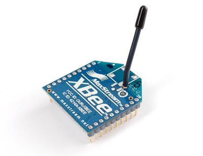
Introduction to XBee Module


Hello friends! In this tutorial, we will learn how an XBee module carries data between electronic devices without a signal cable. We will begin with a simple wireless sensor example, identify the hardware and communication settings involved, and then work through the calculations that help us choose a power supply and estimate data capacity.
This is the first lesson in our XBee series. After understanding the module, you can follow Interfacing of XBee with Computer to configure two radios, followed by XBee Arduino Interfacing to exchange commands between microcontrollers. The same basic reasoning applies to PIC, STM32, and other controllers with a compatible serial interface.
What Is an XBee Module?
XBee is a family of wireless communication modules manufactured by Digi International. A module combines a radio with firmware that handles communication functions. Your controller supplies application data, such as a temperature reading, and the radio sends it to another compatible device.
For example, imagine a temperature sensor in a greenhouse and a display inside your house. The greenhouse controller reads the sensor and produces a short message. Its XBee transmits that message. A second XBee receives it and passes the data to the display controller, which interprets the value and updates the screen.
The two modules are transceivers, so either end can send or receive. Calling one the transmitter simply describes its role in a particular exchange. The display controller can also request a new reading, and the greenhouse node can reply over the same link.
There are several XBee hardware generations, packages, and firmware families. Before following a wiring diagram, read the module label and identify its firmware in Digi's configuration software. A familiar outline or the word XBee alone does not establish electrical or radio compatibility.
XBee, Zigbee, and IEEE 802.15.4
These names describe different things. XBee is a product family. IEEE 802.15.4 defines radio and medium-access functions used by several networking systems. Zigbee adds higher-level networking and application behavior. DigiMesh is Digi's mesh networking protocol. We therefore need to specify both the hardware and the firmware when describing a project.
| Option | Main idea | What to establish before use |
|---|---|---|
| 802.15.4 firmware | Direct radio links and multipoint communication | Compatible radios, channel, network identifier, and addressing |
| Zigbee firmware | A network using coordinator, router, and end-device roles | Network formation, joining, security, and device roles |
| DigiMesh firmware | A mesh in which nodes use a common node type | Compatible firmware and mesh configuration |
| Other XBee families | Different connectivity options, including cellular products | The specific product's interface, service, and network requirements |
Digi explains the networking differences in its Zigbee and DigiMesh comparison. Its XBee compatibility guidance is useful when matching modules from different generations. Two radios operating at 2.4 GHz still need compatible protocols and settings to exchange useful data.
Our introductory wiring reference below concerns the classic 20-pin, through-hole XBee S1 802.15.4 module. Later products can have different current requirements, pin functions, and configuration procedures. Use this lesson to understand the decisions, then apply the specifications for the module on your desk.
How Data Moves Through an XBee Link
Let us follow one greenhouse reading through the system. The controller measures 24.6 degrees Celsius and formats the characters TEMP,24.6, followed by a newline. It sends those bytes through its UART transmit pin to the local XBee's data input.
The local radio packages the serial data for wireless transmission. The receiving radio recovers the payload and supplies it through its data output. The second controller collects characters until the newline, checks the message type, and converts the numerical field into a temperature.
This gives us three separate interfaces to understand:
- The transmitting controller's UART connection to its radio.
- The wireless link between the radios.
- The receiving radio's UART connection to its controller.
A problem in any one of these interfaces can stop the application. If the receiver shows unreadable characters, investigate its local serial settings before changing radio addresses. If both modules respond to local commands but exchange no data, investigate the radio configuration and destination settings.
The application also needs a message format. Sending a stream of numbers without separators gives the receiver no reliable way to identify individual readings. For an introductory project, a line containing a message type, sequence number, and value is easy to inspect: TEMP,17,24.6. A sequence number helps you notice missed or repeated messages.
XBee S1 Pinout and Electrical Connections
The following pins refer specifically to the classic through-hole S1 module. Signal directions are described from the radio's perspective. Consult the package drawing in the XBee S1 user guide to identify pin 1 before wiring.
| Pin | Signal | Purpose |
|---|---|---|
| 1 | VCC | Module supply |
| 2 | DOUT | UART output to the host's RX input |
| 3 | DIN | UART input from the host's TX output |
| 5 | RESET | Active-low reset; use the specified open-drain interface |
| 6 | PWM0/RSSI | Configurable PWM or received-signal indicator |
| 9 | DTR/SLEEP_RQ | Sleep-control function |
| 10 | GND | Supply and signal reference |
| 12 | CTS/DIO7 | Configurable serial flow-control output |
For a simple UART connection, connect host TX to radio DIN and radio DOUT to host RX, with a common ground. TX and RX labels can be confusing on adapter boards, so follow the signal direction in the adapter schematic.
A breakout board makes the 2 mm radio headers easier to use with common breadboards. Check what that board actually provides. Some boards only rearrange pins; others include a voltage regulator, logic translation, or a USB serial interface. A socket and a power LED do not prove that the board accepts 5 V signals.
Choosing the Power Supply
For the legacy S1 family, Digi lists a 2.8 to 3.4 V supply range. Its legacy product comparison lists approximately 45 mA transmit and 50 mA receive current for the standard module, with substantially higher transmit current for the PRO version. These are model-specific figures, not a supply specification for every XBee. See Digi's 802.15.4 module specifications.
Choose a regulator using the highest relevant operating current, its transient response, the other loads on the rail, and suitable design margin. A module can appear healthy while idle and reset when transmission increases the load. Measure the voltage at the radio pins; a long wire can lose voltage even when the regulator itself reads correctly.
The classic Arduino UNO Rev3 specifies only 50 mA available from its 3.3 V pin. That leaves little margin for a standard legacy S1 and is unsuitable for an S1 PRO requiring much higher transmit current. An adequately rated external regulator or properly designed shield is a better starting point. Check the UNO Rev3 specifications rather than assuming every Arduino power pin can supply a radio.
Worked Example: Regulator Heating
A linear regulator turns the voltage difference between its input and output into heat. Ignoring its small quiescent current, we can estimate the dissipation using:
P = (Vin - Vout) × I
For an illustrative 200 mA load supplied from 5 V and regulated to 3.3 V:
P = (5 - 3.3) × 0.200 = 0.34 W
Starting from 12 V instead gives (12 - 3.3) × 0.200 = 1.74 W. The load receives the same regulated voltage, but the regulator must dispose of much more heat. Package thermal resistance and PCB copper then become important. A switching regulator may be more appropriate when the input voltage is much higher than the required radio supply.
Matching UART Logic Levels
Power voltage and signal voltage are separate questions. A radio powered correctly at 3.3 V can still be damaged by an incompatible voltage at DIN. With a 5 V controller, provide suitable translation on signals entering the XBee. Also check that the radio's output meets the controller's input-high specification.
A voltage divider illustrates how one-way level reduction works. If a resistor connects host TX to DIN and another connects DIN to ground, the unloaded output is:
VDIN = VTX × Rbottom / (Rtop + Rbottom)
Using 10 kΩ above the node and 20 kΩ below it gives 5 × 20 / (10 + 20) = 3.33 V nominally. This explains the principle, but resistor tolerances, input loading, capacitance, and supply variation affect the real waveform. Use a properly specified logic translator for a robust design, especially with faster serial data or longer connections.
Do not place that divider on the radio's supply pin: a signal divider is not a regulated power source. Likewise, a true RS-232 port requires a suitable transceiver; it cannot be connected directly to the XBee's logic-level UART. We will address computer adapters in the next lesson.
Transparent Mode and API Mode
Transparent mode makes the radio behave like a serial link from the application's point of view. Your controller sends payload bytes, and a compatible destination receives those bytes. It is convenient for learning because you can inspect the traffic with an ordinary serial terminal.
API mode adds a defined frame structure between the host and its local radio. Depending on the product, these frames can carry destination information, incoming source addresses, configuration requests, and transmit status. The host must construct and parse the appropriate frame types. Digi's comparison of transparent and API modes describes this distinction.
| Requirement | Transparent mode | API mode |
|---|---|---|
| Send simple text to a fixed destination | Convenient starting point | Possible, with frame handling |
| Select a destination for individual messages | Usually requires configuration changes | Addressing can travel in the request frame |
| Identify incoming senders | Include identity in application data | Supported receive frames provide source information |
| Inspect transmission outcomes | Use an application acknowledgement | Use supported status frames and application acknowledgements |
A radio acknowledgement and an application acknowledgement answer different questions. The radio may report successful delivery while the receiving application rejects an invalid command. For a control project, define a reply such as ACK,17,LED_ON after the receiver has actually processed command 17.
Configuration Before Connecting a Microcontroller
Begin with two compatible radios on suitable USB adapters. Use Digi XCTU to identify them and read their settings. Record the hardware and firmware information before making changes. Installing firmware should be a deliberate compatibility decision, not the first response to a loose wire.
- Identify the module family and firmware at both ends.
- Set each host's serial connection to match its local radio.
- Configure the network and destination settings required by that firmware.
- For this introductory serial exercise, use transparent mode.
- Write the configuration to the module and exchange a short message in each direction.
Keep both ends at 9600 baud initially to simplify the setup. However, the baud rate is a property of each local UART connection; it is not the over-the-air radio rate. Different local baud rates can work, but a slow receiving interface can become a bottleneck and fill buffers.
For classic S1 short-address examples, you will encounter MY for the local address and DH/DL for the destination. Zigbee uses its own addressing and joining behavior. Follow the computer-interfacing lesson's stated firmware assumptions before copying its commands.
Calculating Serial Data Capacity
The radio's advertised RF data rate is not the number of application bytes your program can send every second. UART framing, packet overhead, acknowledgements, contention, retries, and receiver processing all affect the result.
With 8N1 serial framing, each byte uses one start bit, eight data bits, and one stop bit. The theoretical UART byte rate is therefore:
Byte rate = baud rate / 10
At 9600 baud, that gives 9600 / 10 = 960 bytes/s. A 32-byte message occupies 32 × 10 / 9600 = 0.0333 s, or about 33.3 ms, on one UART interface. This is a serialization calculation, not a measured end-to-end wireless delay.
Suppose ten sensor nodes each send a 32-byte record once per second. Their combined application payload is 10 × 32 = 320 bytes/s. A 9600-baud receiving UART has theoretical room for that payload, but you must also account for framing added by your application or API mode, burst arrival, and retransmissions.
If all ten nodes transmit on exactly the same schedule, average traffic alone can hide a burst problem. Staggering reports and implementing flow control where supported can help. A larger baud rate cannot repair a weak RF link, and a stronger radio cannot fix a receiver that stops reading its UART buffer.
Range, Antennas, and Link Margin
Indoor walls, antenna placement, metal enclosures, and interference can make two installations perform very differently. Treat a published line-of-sight range as a specification under stated conditions, then evaluate the actual site. Test with the enclosure closed and equipment operating as it will in service.
A basic link-budget calculation helps explain why range changes:
Preceived = Ptransmit + GTX + GRX - Lpath - Lother
Power terms are in dBm, antenna gains in dBi, and losses in dB. For a hypothetical 0 dBm transmitter, two 2 dBi antennas, 80 dB path loss, and 2 dB additional loss, received power is 0 + 2 + 2 - 80 - 2 = -78 dBm. If the selected receiver's specified sensitivity were -92 dBm, the calculated margin would be 14 dB.
These are illustrative inputs, not a prediction for a particular XBee installation. Fading and interference can consume that margin. RSSI is useful evidence about a received signal, but it does not by itself describe packet loss, latency, or every obstruction along the path.
Power Consumption and Sensor Reporting
Battery life depends on how long the radio and controller spend in each operating state. Sending one short reading per minute is a different workload from leaving the receiver continuously awake. Sleep settings must also fit the network's delivery requirements.
For an illustrative sensor node, assume an entire-node active current of 50 mA for 0.1 s every 10 s and a sleep current of 0.01 mA for the remaining 9.9 s:
Iaverage = (50 × 0.1 + 0.01 × 9.9) / 10 = 0.5099 mA
An idealized 2000 mAh battery would then provide 2000 / 0.5099 = 3922 hours, approximately 163 days. Real operation will be shorter or otherwise differ because capacity depends on load and temperature, and regulators, startup time, battery aging, and extra receive time affect consumption. This calculation is a planning example, not a battery-life claim for an XBee product.
Common Problems and Practical Checks
| Symptom | Likely area | Useful first check |
|---|---|---|
| No response from a local module | Power, adapter, serial connection, or sleep state | Check supply at the module and the selected computer port |
| Unreadable characters | Local UART configuration | Compare baud rate, parity, and stop-bit settings |
| Local configuration works, radio data does not | Protocol or network settings | Compare firmware, network membership, and destinations |
| Communication works in one direction | Return address or one UART path | Check both destination configurations and both RX connections |
| Reset occurs during transmission | Power delivery | Investigate regulator capacity and voltage drop |
| Short messages work, continuous data fails | Buffering or throughput | Reduce the offered data rate and inspect flow-control behavior |
Change one variable at a time and keep a short record of the result. If you alter addressing, baud rate, and firmware together, a successful connection will not tell you which change solved the problem. The same approach makes failures easier to reproduce.
Practical Review: Where XBee Fits
XBee is useful when a project needs a documented radio interface and the selected firmware provides the required networking behavior. Wireless sensing, robot telemetry, and a remote operator panel are suitable examples. A serial interface can keep the controller's application code relatively small.
The engineering tradeoffs include module cost, supply design, antenna placement, network configuration, and the available application throughput. For a two-node text link, mesh routing may add unnecessary setup. For a building containing many sensor nodes, routing and maintenance requirements may be central to the design.
Security also needs explicit configuration. A network identifier is not a password, and encryption does not prevent RF interference. Decide how devices obtain keys, how commands are authorized, and what the application does when communication stops. A remote actuator should have a defined communication-loss behavior.
Our next step is to configure two radios and exchange messages from a computer. Once that path works, replacing the terminals with microcontroller programs becomes a much more manageable task.
Frequently Asked Questions
Is every XBee a Zigbee module?
No. XBee covers several hardware and firmware families. Check the exact product and loaded firmware before applying Zigbee addressing, joining, or coordinator instructions.
Do I need two XBee modules?
You need two compatible radio endpoints for the basic wireless exercise. One can be connected to a computer and the other to a microcontroller. Both endpoints can transmit and receive.
Can I connect a bare XBee directly to a 5 V Arduino?
Plan the supply and logic interface separately. Use the radio's specified supply voltage and current capacity, and suitable translation for signals that would otherwise exceed its input limits.
Does the radio understand commands such as LED_ON?
In a basic transparent serial project, those characters are application payload. Your receiving controller must recognize the command, validate it, and change the output.
Why is my data rate lower than the RF specification?
The complete path includes serial framing, packet overhead, shared-channel access, retries, and application processing. Calculate your required payload rate and measure performance with the intended message size and workload.
Can I use Proteus instead of testing the hardware?
A simulation can help you explore program flow and supported serial behavior. It cannot establish real antenna range, supply stability, or operation of firmware features that its model does not implement. Use hardware measurements for those questions.
Comments
0