


Circuit Designing of LCD with Arduino in Proteus ISIS


Hello friends! Today, we will design a circuit containing an Arduino UNO and a 16 × 2 character LCD in Proteus ISIS. We will connect the display, write a small Arduino sketch, compile it and load the resulting program into the simulated UNO. Our first result will be the website name displayed across two rows.
LCD Simulation Libraries
Latest library: LCD Library for Proteus V3.0 (October 2026): LCD 16x2, LCD 20x4 and both I2C LCDs in one library, with our own HD44780 model and an Arduino demo
Helping Tools
- Serial Monitor Advance: a serial terminal window for the UART of your board
- Serial Monitor Expert: the serial monitor with extra debugging tools
This is a useful beginner project because the visible result is simple while the underlying connections teach several important ideas: control signals, a four-bit data bus, contrast adjustment and the relationship between source code and a compiled program. We will examine each part before adding changing values to the display.
If Arduino components are not available in your Proteus installation, begin with our Arduino Library for Proteus tutorial. The exact device library and simulation support depend on your installation. Once you can place a supported UNO model, you are ready to follow this circuit.
What Type of LCD Are We Using?
We are using a character display with an HD44780-compatible parallel interface. A 16 × 2 display provides sixteen character positions on each of two rows. It is different from a graphical display, and it is also different from a character display fitted with an I2C backpack.
The Arduino LiquidCrystal library supports the parallel interface used here. Our example follows the pin arrangement in Arduino's official LiquidCrystal HelloWorld example. We will send data using four LCD data lines rather than eight, leaving more Arduino pins available for other parts of a project.
An I2C backpack contains additional interface hardware and normally needs a different connection arrangement and library interface. If your physical module exposes only power, ground, SDA and SCL, do not try to copy the six Arduino signal connections from this tutorial directly onto it.
Components and Software
| Item | Purpose | Important detail |
|---|---|---|
| Arduino UNO simulation model | Executes the compiled sketch | Use an ATmega328P-based UNO configuration |
| 16 × 2 parallel character LCD | Displays the two text rows | Match the controller and pin labels |
| Contrast potentiometer | Sets the voltage on the LCD contrast input | A 10 kilohm potentiometer is a common starting arrangement |
| Power and ground terminals | Provide the circuit reference and supply nets | All relevant grounds must connect |
| Arduino IDE and LiquidCrystal library | Build the program | Select the UNO target before compiling |
| Proteus ISIS | Simulates the schematic | The installation must support the selected processor model |
For physical hardware, also check the LCD's supply specification and backlight requirements. A simulator symbol may omit backlight pins or simplify the visual contrast behavior. That does not remove the corresponding requirements from the real module.
Our LCD library for Proteus provides another display-library reference. Use a compatible component available in your setup; the lesson depends on the signal interface, not on a particular drawing style.
Understand the LCD Pins Before Wiring
The LCD has power pins, control pins and data pins. RS selects whether the transferred byte is a command or character data. E is the enable signal used during the transfer. R/W selects reading or writing; this circuit writes to the display and connects R/W to ground.
In four-bit mode, each byte is transferred in two parts over LCD data lines D4 through D7. The library manages those transfers for us. LCD pins D0 through D3 are unused in this arrangement. Do not confuse the LCD's D4 label with Arduino digital pin 4; the wiring table specifies the connection between the two naming systems.
| LCD signal | Common header position | Connection in this tutorial |
|---|---|---|
| VSS | 1 | Ground |
| VDD | 2 | Compatible supply, normally 5 V for this example |
| VO or VEE | 3 | Contrast potentiometer wiper |
| RS | 4 | Arduino D12 |
| R/W | 5 | Ground |
| E | 6 | Arduino D11 |
| D0 to D3 | 7 to 10 | Unused in four-bit mode |
| D4 | 11 | Arduino D5 |
| D5 | 12 | Arduino D4 |
| D6 | 13 | Arduino D3 |
| D7 | 14 | Arduino D2 |
Header positions shown here are common for this display family, but use the actual module's pinout when building hardware. Connect the outer terminals of the contrast potentiometer between supply and ground, with the wiper connected to VO. The potentiometer adjusts the contrast input; it is not a series resistor for the display's power supply.
Build the Circuit in Proteus ISIS
- Create a new schematic and place the supported Arduino UNO model.
- Place a compatible 16 × 2 character LCD.
- Add the supply, ground and contrast control required by the model.
- Connect RS, E and the four data lines according to the table.
- Connect R/W to ground and check the LCD supply connections.
- Inspect junctions and net labels before loading the program.
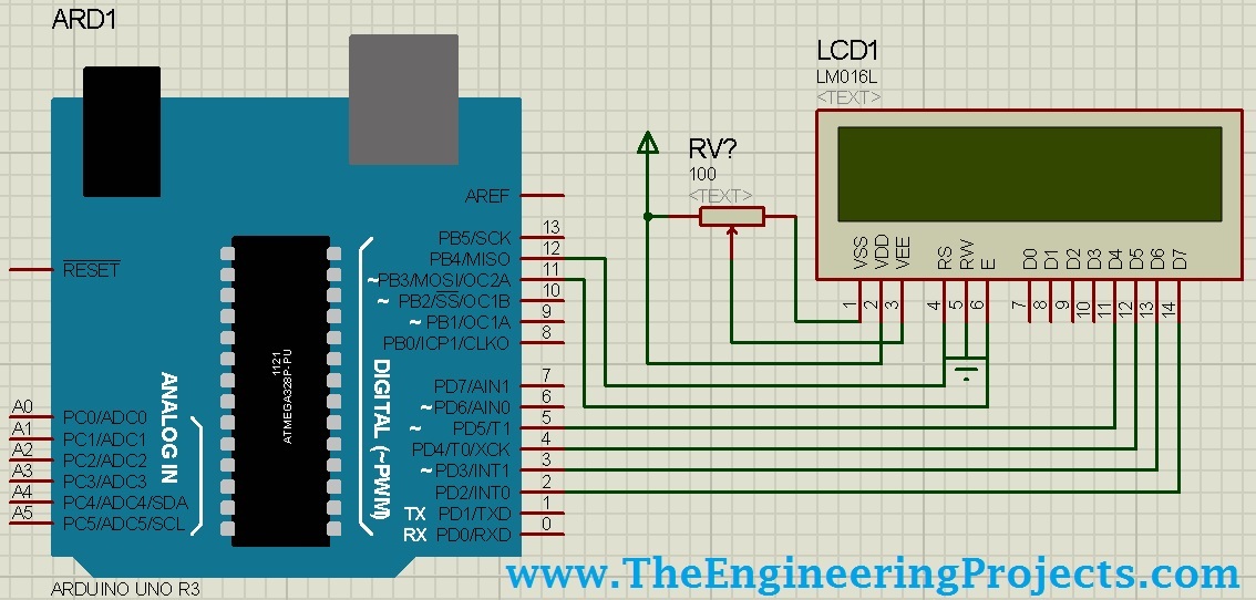
The original schematic above shows the arrangement used for this demonstration. Trace each connection by its endpoints rather than by its color or apparent position. Two wires crossing on the screen do not necessarily form a junction, and a wire that looks close to a pin may still be unconnected.
One productive way to inspect the circuit is to start at the Arduino constructor in the next section and trace its six signals in order. This makes it easier to find swapped data lines than looking at the complete schematic and hoping something appears wrong.
Write the Arduino LCD Program
Open the Arduino IDE, select Arduino UNO and create a new sketch. Enter the following program. It retains the original demonstration text, split over the display's two rows.
#include <LiquidCrystal.h>

LiquidCrystal lcd(12, 11, 5, 4, 3, 2);

void setup() {
  lcd.begin(16, 2);
  lcd.print("www.TheEngineer");
  lcd.setCursor(0, 1);
  lcd.print("ingProjects.com");
}

void loop() {
  // The static message does not need repeated updates.
}
The include statement makes the library declarations available to the sketch. The constructor assigns Arduino pins in the order RS, enable, LCD D4, LCD D5, LCD D6 and LCD D7. If you choose different Arduino pins, change both the constructor and the schematic. Changing only one side breaks that agreement.
lcd.begin(16, 2) initializes the interface for sixteen columns and two rows. The first print begins at the initial cursor position. lcd.setCursor(0, 1) then selects column zero of row one, which is the first position on the second visible row. The row and column indices start at zero.
Each string in this demonstration contains fifteen characters, so each fits within a sixteen-character row. Splitting the text manually keeps the result clear. Do not depend on writing a long string past the end of the first row to place the remainder where you expect on the second row.
Install the Correct Library
If the compiler cannot find LiquidCrystal.h, install the Arduino LiquidCrystal library through the IDE's library management facilities. Read the library name carefully; similarly named I2C libraries are not interchangeable with this constructor.
The original downloadable LiquidCrystal archive is retained below for readers reproducing the older project. Prefer the maintained official library for a new setup, and avoid installing several conflicting copies at once.
Download LiquidCrystal Arduio Library
When the IDE reports that multiple libraries match an include, inspect which one it actually selected. Keep a note of the selected library and board package with the project. This is especially useful when moving an old sketch to another computer.
Compile and Load the Program into Proteus
Proteus needs a compiled program for the simulated microcontroller. The Arduino source file is not that program. For the AVR-based UNO model used here, a HEX file is the usual artifact loaded into the model's Program File property.
- Save the sketch in a known project folder.
- Select the Arduino UNO target and compile the sketch.
- Use the IDE's Export Compiled Binary command to create a retained build artifact.
- Locate the exported UNO HEX file in the sketch's output location.
- Stop the Proteus simulation and open the UNO component properties.
- Select that HEX file as the Program File.
- Check that the simulated processor clock matches the UNO build, normally 16 MHz.
Arduino describes binary export in its platform specification. Output layout can vary with the IDE and board package, so inspect the export result instead of relying on an old temporary-directory path. Our Arduino HEX-file tutorial gives additional background.

If export produces both an ordinary sketch HEX and a version that includes a bootloader, use the artifact expected by your simulation model. For a model executing the sketch directly from the processor's normal reset address, the ordinary sketch HEX is the appropriate starting choice. Do not add a bootloader merely because its filename sounds more complete.
A common debugging mistake is recompiling the source but leaving Proteus pointed at an older file. Keep one clear output path, rebuild after each code change and restart the simulation with the intended artifact. A deliberate change to a short test message is an easy way to establish which build is running.
Run the LCD Simulation
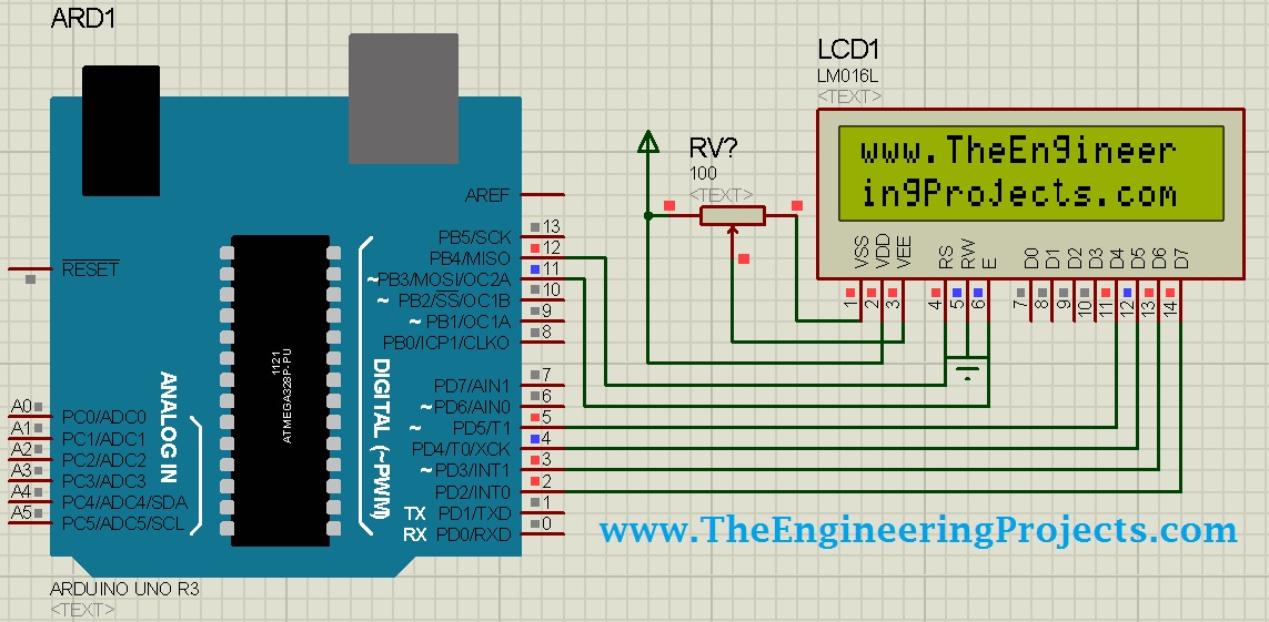
Start the simulation. The expected result is the website name split across the two LCD rows, as shown in the original result image below. If the characters are invisible, investigate contrast and initialization separately instead of immediately replacing the sketch.
For the first run, keep the program static. Once both lines appear in the correct positions, you have evidence that the basic signal mapping and initialization are functioning in the model. That is a good point to save the schematic before experimenting with counters, sensors or scrolling text.
Display a Changing Value Without Leaving Old Digits
Suppose the second row first contains the number 100 and later contains 9. Printing only the new digit over the first position can leave the two old zeros visible. The LCD stores characters until they are replaced or cleared; a shorter print does not automatically erase the rest of the previous field.
For a small example, overwrite the entire second row at a modest rate. The following alternative sketch displays an elapsed-seconds counter. It avoids clearing the complete screen on every loop and uses unsigned elapsed-time arithmetic for the update interval.
#include <LiquidCrystal.h>
LiquidCrystal lcd(12, 11, 5, 4, 3, 2);
unsigned long lastUpdate = 0;

void setup() {
  lcd.begin(16, 2);
  lcd.print("Elapsed seconds:");
}

void loop() {
  unsigned long now = millis();
  if (now - lastUpdate < 1000UL) return;
  lastUpdate = now;
  lcd.setCursor(0, 1);
  lcd.print("                "); // Sixteen spaces replace the old field.
  lcd.setCursor(0, 1);
  lcd.print(now / 1000UL);
}
This is an elapsed-time display, not a precision clock. The oscillator and program timebase determine its accuracy, and the counter's underlying millisecond value eventually wraps. For an instrument that needs calendar time or long-term clock accuracy, select an appropriate time source and define the required behavior.
For a more polished screen, format a fixed-width field in a buffer and write it once. That reduces visible intermediate clearing and keeps units aligned. Decide how many positions belong to a sign, decimal point and unit before choosing the number of decimal places.
Useful Hardware Calculations
A 10 kilohm contrast potentiometer connected across 5 V draws approximately I = V / R = 5 / 10000 = 0.0005 A, or 0.5 mA, through its end-to-end resistance. Its dissipation is P = V² / R = 2.5 mW. This calculation concerns the potentiometer only; it does not describe the LCD controller or backlight current.
The backlight may need a series resistor if the module does not already include one. As an illustrative calculation, a 5 V supply, a 3.0 V LED forward drop and a desired 10 mA current give R = (5 − 3) / 0.010 = 200 ohms. A nearby higher standard value limits current somewhat further. Use the actual backlight specification and account for component tolerances rather than treating these example values as universal.
Do not power a backlight of unknown current directly from an Arduino signal pin. The backlight and the logic interface serve different purposes. A display can have an illuminated background while its controller is uninitialized, and it can show characters without a powered backlight when the viewing conditions permit.
Troubleshooting the LCD Circuit
| Problem | Likely cause | Next check |
|---|---|---|
| No visible characters | Contrast, power or program not running | Check supply nets, contrast and loaded HEX |
| Blocks appear but text does not | Initialization or control-signal fault | Inspect RS, E, R/W and the constructor |
| Garbled characters | Swapped data lines or incompatible timing | Trace D4 through D7 and check the processor clock |
| Second row stays empty | Cursor or geometry mistake | Use begin(16, 2) and setCursor(0, 1) |
| Old digits remain | New text is shorter than the previous field | Overwrite a fixed-width field |
| Code changes do not appear | Simulation uses an old artifact | Re-export and inspect Program File |
| Library include fails | Missing or wrong library | Install the parallel LiquidCrystal library |
Use the static two-line program as a reference when troubleshooting. If that works but the changing-value sketch does not, focus on the new code. If neither works, investigate the common wiring and simulation configuration before adding more display features.
Plan a Sixteen-Character Sensor Row
Before replacing the counter with a measurement, sketch the row on paper. For example, the text Temp: -12.3 C occupies thirteen positions: six for the label and following space, five for the signed number, one space and one unit character. That leaves three positions unused. A value with an additional digit needs another position, so choose the field width from the largest expected reading rather than from the first value you observe.
Keep measurement validity separate from its numeric value. If the sensor fails, write a clear error indication over the complete old field rather than leaving the previous number visible indefinitely. Otherwise, a person looking at the screen may mistake a stale measurement for a current one. During development, deliberately display a long value, a shorter value and an error message in sequence to check the formatting.
Also choose a display update interval independently of the sensor sampling interval. A sensor may be sampled frequently for processing while the LCD updates only a few times each second. This keeps the screen readable and reduces unnecessary interface traffic without forcing the measurement algorithm to run slowly.
Review and Next Steps
This project gives us a clear connection between a circuit diagram and an Arduino library constructor. We know which pins carry control signals, why four data lines are sufficient, how the cursor selects a row, and why Proteus needs a compiled artifact. Those ideas remain useful when the displayed value comes from a real sensor.
A sensible next exercise is to add a short label and one changing number, keeping the complete row within sixteen positions. Then try our scrolling text with Arduino tutorial. Add one behavior at a time so that a display-formatting issue remains easy to separate from a wiring issue.
Frequently Asked Questions
Do I need a physical UNO connected to simulate this circuit?
Not for the processor simulation described here. Proteus executes the selected program using its supported model. A physical UNO is needed when you move to a hardware test or deliberately use a hardware-in-the-loop arrangement.
Can I use different Arduino digital pins?
Yes, provided the chosen pins are suitable and available. Update the six constructor arguments and all corresponding wires together. Keep a wiring table with the sketch so the mapping remains obvious.
Why is the main loop empty in the first example?
The message is written once during setup, and the display retains it. Reprinting a static message continuously adds work without improving the result. Use the loop when the content actually needs to change.
Why does my I2C LCD not match this tutorial?
Its backpack converts a serial bus into the LCD's parallel signals. That requires a different circuit and software interface. Identify the hardware before selecting a library rather than choosing one only because its name includes LCD.
Does a successful simulation prove the physical circuit will work?
It helps check the modeled wiring and program behavior. Real hardware still requires correct supply voltage, contrast, backlight current, grounding and reliable connections. Inspect those items when transferring the design to a breadboard.

Tags


Is it possible to simulate Arduino DUE in proteus?
1 reply
Not rite now, the arduino library for proteus doesn't support Arduino DUE
Which pins of the lcd are grounded?4,5,6 or only 5?
1 reply
Only pin # 5 is grounded.
hi,
im receiving Errors when compiling your code above , any suggestions?
Would this cause an issue when i upload he Hex code in Proteus ?
1 reply
Hi,
The error comes is because of " this sign so simply remove this sign and add it again your code and it will start working.
Thanks.
Can you explain on how to debug this code on Proteus? That's something I really wanna learn. Thank you.
1 reply
Hi,
We can't debug code on Proteus, we just upload the hex file in proteus. Although, we can debug the code in almost all compilers.
Thanks.
hello i just uploaded your code but data from digital pins is not going to lcd..and so that it shows blank lcd ..can u suggest me what to do????
Hello,
Dear Syed Zain Nasir
When programming MK I have a problem simulating the operation of the LCD display on the 12864 DFRobot SPI (controller ST7920) in Proteus 8. Here the link to the display: "3-wire Serial LCD Module (Arduino Compatible) (SKU:DFR0091)"
. Where can I find this display of the VSM model? In this library it is? I work with the display in parallel mode. Is that possible? Or not? I need to look sophisticated multi-level menu options, and graphics. I really important is your answer.
Regards
1 reply
Hi,
Yeah it can be done quite easily, add me on Skype and let me know the details. My Skype id is "theenggprojects".
Thanks.
there is no error while compiling,the LCD turns on,the led's showing the same way but the letters on the lcd are not showing up,i see a blank lcd in light green colour,please can u help me?
Hi,
i use proteus 8.5 and available arduino library from proteus. i try wiring lcd to pin arduino but i cant wire it. how should i do? i hope you can make tutorial with proteus 8.5 :)
Thanks
Syed Zain Nasir
First thank you for all your great works. I wonder if you have the library for Arduino GY-521 MPU-6050 Module 3 Axial Gyroscope Accelerometer Stance Tilt, by any chance.
Tony
hey dear ,
what is invalid opcode 0x9419 at pc=0x095A mean?
and how can i fix it?
thanks for ur help.
hye.. i gkt this problem which make me complete blunt on my project.. i have seen many connection for lcd, i make connection gnd(1,5) vdd and vee loop (2,3) pin lcd 4 to arduino 12 and pin lcd 5 to arduino 11 for D4(11),D5(12),D6(13),D7(14) at arduino 5,4,3,2 .. please help me is this right or wrong or contact me at adamizrul@gmail.com..
earnest needed help
1 reply
You can download working simulation from this tutorial. Click on the button above to download.
please I need RFID library am designing a project that required it thanks
Hi Syed,
I run the simulation and I got "Invalid opcode 0x9419 at PC=0x0A94".
1 reply
Have you added the hex files of Arduino and LCD ?
Comments
22