


Capacitance Measurement using Arduino


Rather than investing in new electronic equipment, we will use an Arduino board and some basic components to measure the capacitance. To make this project, we should have some working knowledge about the capacitor. Here, we will not discuss the in-depth working of capacitors, but we will talk briefly so that it would be easy to understand the working principle of our project.
The capacitor is an electronic component that basically stores the energy when applied to an electric field. It has two parallel terminals connected by two parallel conducting plates separated by a dielectric material. Dielectric materials are electrical insulators(resist to pass the current) that can be polarised by applying an electric field. When we connect a battery with the capacitor then due to potential difference, the electric field is created between two oppositely charged plates of the capacitor and this way the capacitor stores the energy.
Software to install
To make this project, we will need some software to install. As we will make our project in the simulation, so for that we will install Proteus simulation software and for coding, we will use the Arduino IDE.
A brief about Proteus, it is a tool used for simulation and design of electronic circuits. Here we can design different types of electronic circuits and run the simulation. Although Proteus has a very big database for electronic components, still we need to install some libraries which we will use in this project.
- Arduino UNO - We have to install the library for Arduino UNO.
- LCD module - We have to install a library for the LCD module.
You can download this whole project for example Proteus Simulation and Arduino Code, by tapping the below button:
Capacitance Measurement using ArduinoProject overview
In this project, we will use the following components-
- Arduino UNO - We will use this as the main controller for this project. It will calculate the capacitance of the capacitor.
- 16x2 LCD Module - We will use this to show the result of measured capacitance and some user-related messages.
- Resistors and Capacitors - We will be using some resistors to make the RC circuit which is required for measuring the capacitance.
Now let's talk about the working of this project. The capacitance of any capacitor is the amount of charge that is stored in that capacitor and its unit is Faraday (F). To measure the capacitance, we will use some basic properties of the capacitor.
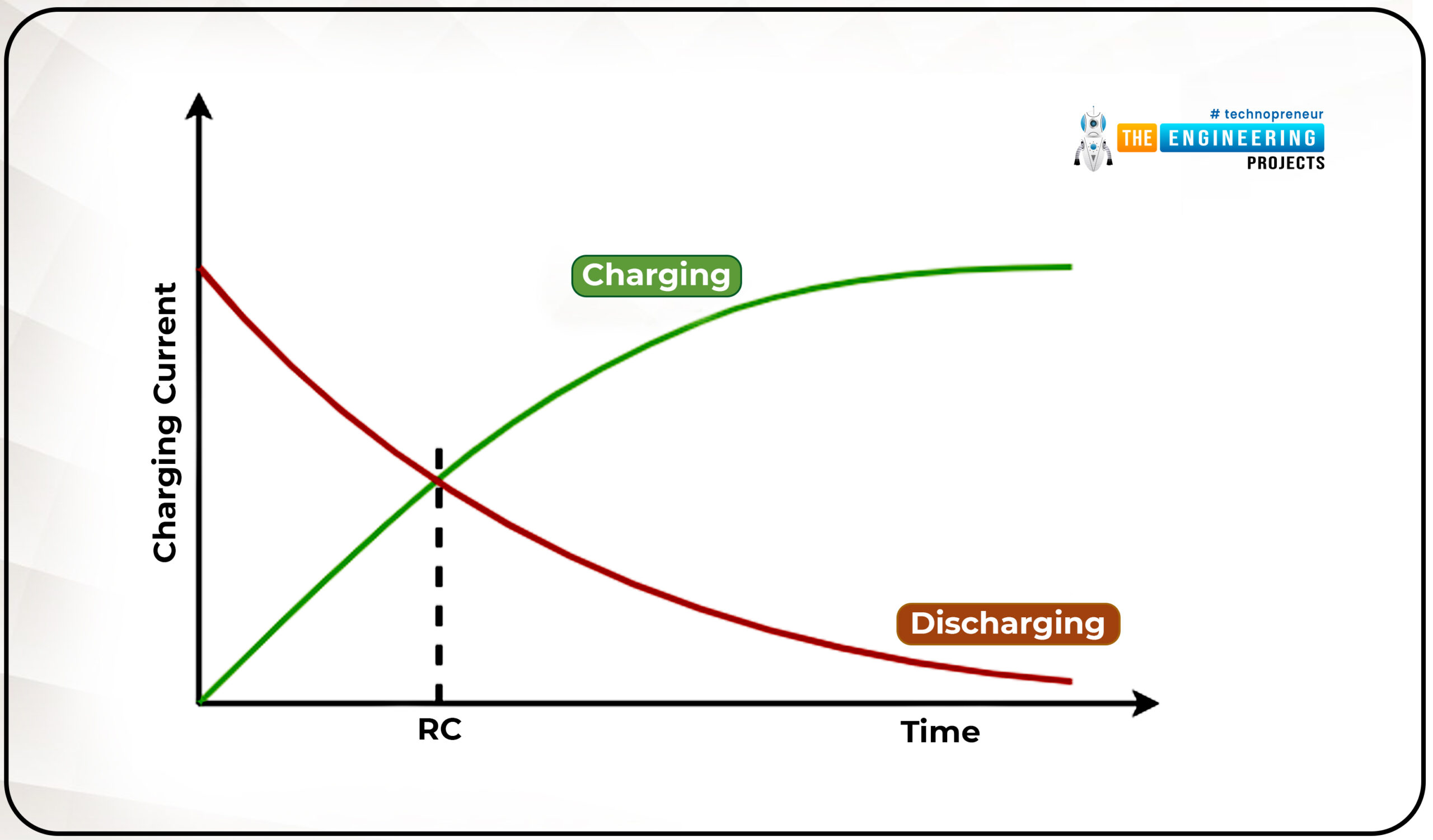
So when we connect a power supply with a resistor across the terminals of a capacitor, it will take a certain amount of time to fully charge. And when we connect any discharging resistor as a load across it, then it will take a certain amount of time to fully discharge. And this charging and discharging time will be proportional to the capacitance of the capacitor and the charging resistor in the RC circuit.
We will use the time constant formula for the calculation of capacitance. The time constant of any capacitor is known as the time taken by the capacitor to charge 63 percent of applied voltage or the time taken by the capacitor to discharge to 33 percent of stored voltage.
Here,
T (Tau) = Time constant(Seconds)
R = Resistance (Ohms)
C= Capacitance (Farads)
Using the above principle, we will charge the capacitor using a resistor to reach the charge of the capacitor to 63 percent of applied voltage and we will measure the time taken by the capacitor to reach that point. As we know the resistor’s value and time constant, using these two, we can calculate the capacitance:
Components required
- Arduino UNO
- 16x2 LCD module
- 10 kOhms Resistor
- 220 Ohms Resistor
- An unknown capacitor(Enter range here )
Components details
1. Arduino UNO
- Arduino UNO is an open-source development board that will be used to measure capacitance.
- It comes with 14 digital I/O pins and 6 analog I/O pins.
- It has 1 UART, 1 SPI, and 1 I2C hardware which are multiplexed with GPIO pins.
- Digital pins can be used for input and output for digital data. In this project, we have used digital pins for charging the capacitor.
- Analog pins have 10 bits of ADC (Analog to Digital convertor) resolution ranging values from 0 - 1023.
- Analog pins can be used for input and output purposes. In this project, we have used analog pins as input for measuring the discharge and charge voltage.
Note-Whenever uploading the code on the Arduino UNO, disconnect any wire which is connected to Rx(D0) and Tx(D1) pins, otherwise, it will give an error while uploading the code.
2. LCD Module
- LCD stands for Liquid Crystal Display, and its display is made using liquid crystal technology.
- For more knowledge of how LCD works, prefer this link Working of LCD display.
- We have used a 16x2 LCD display in this project.
- The LCD module works in two different data modes: 8-bit or 4-bit mode.
- We have used 4-bit mode which means we can send 4-bit data in a single cycle to the LCD module.
- We have used an LCD module to display the user-related information such as capacitance value and the welcome message.
3. Resistors and Capacitors
- Resistors, as the name suggests, is an electronic component that controls the flow of current in a circuit.
- Current flowing in any circuit is inversely proportional to resistance.
- They are used mostly in every type of electronic circuit for current limiting, voltage divider, and in some noise filters.
- There are various types of resistors available depending upon the current rating, manufacturing materials, and use case.
- Although we are making this project in simulation, if you want to make this project using the real components for that we will use the carbon composition through-hole resistors.
- Capacitors are electronic components that have the ability to store energy.
- When we connect any battery across the terminals of capacitors then it will start charging.
- We can store a large amount of charge for a very short period of time in capacitors.
Circuit diagram and Working
Now, we have a list of all the required components. Let's start connecting them.
- Make sure, we have the correct version of Proteus and have installed all the required libraries which we will be using in this project.
- Now let’s start creating the new project in the Proteus.
- Import the listed components to the workspace of Proteus.

- Now we have imported all the components to the workspace.

- First, connect the charging resistor of 10K ohms with the digital pin 8 of Arduino UNO and then connect the discharging resistor of 220 ohms with the digital pin 9 of the Arduino UNO.
- We will use the D8 pin for charging the capacitor and the D9 pin for discharging the capacitor.
- Now connect the capacitor which we want to measure in between these two resistors and connect another terminal of the capacitor with the ground.
- Connect an analog pin of Arduino UNO with the discharging resistor terminal and that analog pin will be A0 on Arduino UNO.
- After that, we are finished with our RC circuit.
- Let’s connect the LCD module with the Arduino UNO, as we are using the LCD module in 4 bits mode so we need to connect only four data pins with Arduino UNO.
- Connect D4 pin to D7 pins of the LCD module with D2 to D5 pins of the Arduino UNO.
- While connecting them, keep in mind that they must be connected in the same order.
- Connect the RS pin with the D6 and Enable pin with the D7 pin of Arduino UNO.
- Connect the RW pin with the ground which enables the write mode in the LCD module.
- Connect the 5v power supply with Vdd and Gnd pins of the LCD module.
- Now we have connected all the components.
- Before moving to the coding part, reverify your connections once.

While working on the real components, make sure you have connected the backlight of the LCD module and set the contrast properly otherwise nothing will be visible on the LCD module.
Arduino code of Capacitance measurement-
Downloading and including libraries
- This project will need the library for the LCD module.
- Before going to write, we must download and include all the required libraries.
- We can download the library for the LCD module using this link LCD module library.
- To include the library, go to the Sketch >> Include Library >> Manage Libraries… Using this, we can add libraries directly by searching the window.
- Or if you have downloaded the library using the link then you will have a zip file for the library. In this case, follow this path: Sketch >> Include Library >> Add .Zip Library…

- After downloading the library, we are all set to start our code.
- First, include the LCD library header at the start, make an object for the same, and declare all the pins which are used for the LCD module.

Variable declaration
- Now we will declare all the variables and pins which we are going to use in this project.
- Declare the charging pin, discharging pin, and an analog pin for measuring the charging voltage as 8,9 and A0 respectively.
- Declare variables to store the start time, stop time, and a variable to store the duration.
- Declare a function “measure()” which will read the analog values.

- After the declaration, we will define a function “measure()”.
- We have defined this at the end of the code.

- This function will read the analog values from the pin and return the values for the same.
- Here, we have declared and defined the function separately but we can define the function without declaring it, but it is not a good practice to do so and sometimes that will cause errors in the code also.
Void setup()
- After declaring all the required variables, we will start writing the “void setup()” function.
- This is a built-in function in the structure of the Arduino sketch.
- We can write any code without this function. As per the structure of the Arduino sketch, this function must be in the code.
- In this function, we will write the pin mode and initialization of other peripherals which will be required in the code.
- This function will only run once when the code starts.
- So in this function, we will first begin the LCD module and print the instructions to use.
- Then set the pin mode of pins and the initial state of the pins.

Void loop()
- This is also a built function of Arduino sketch.
- As per the structure of the Arduino sketch, we can not delete this function from the code even though we don’t have anything to write in this.
- This function executes after the “void setup()” function.
- In this function, we will write our main code which we want to run continuously.
- As the name suggests this will run in a loop.
- Initially, when there is no capacitor connected then the analog value will be in the maximum range and that is 1010 to 1030.
- So now, we will display the message that ‘place a capacitor’ and code will be in a while loop until we connect any capacitor to the circuit.

- Now when we connect any capacitor, the above condition will be unsatisfied, then code will enter in a next infinite while and there we will write the process of charging and discharging of capacitor and time constant.
- First, we will discharge the whole capacitor, for that we will run a while loop, and using the measure() function, we will measure the currently stored voltage in the capacitor.

- And when the stored voltage reaches below or equal to the threshold, we will change the pin mode of pins to start charging the capacitor again and store the start time of charging.
- Using the measure() function, monitor the charging voltage in the capacitor and when the stored charge reaches 63 percent which is 648 of 1023 then we will stop the charging and store the stop charging time also.
- And display the charging percent on the LCD module.

- Now calculate the total time taken by the capacitor to reach the 63 percent of charge and that will be the time constant of the capacitor.
- Using the time constant formula, we can calculate the capacitance of the capacitor as we know the charging resistor connected to the capacitor.

- As we know the charging resistor value is 10k ohms, using that when we divide the time taken by the resistor value, then we will get the capacitance.
- And the calculated result will be displayed on the LCD module for 3 seconds, after that code will enter in an infinite while loop.
- Now we have to reset the device to measure any new capacitor value.

- Here, our coding part will be completed, it is time to test our code with the circuit and now we will move to the next section.
Results and Working
- As we are going to test our project in the Proteus simulation, we have to include the hex file of our code in the Arduino UNO module.
- The first step is to generate the hex file of the code.
- Click on the Arduino UNO module in the Proteus then browse to the location of the generated hex file.

- After adding the code, we are ready to run the simulation and click on the Play button to start the simulation.
- First of all when the code starts, on the LCD module, we will show the range of capacitance that can be measured using this device and the message to place the capacitor if it is not placed already.

- When the capacitor is placed, then the discharging process will start to eliminate any pre-stored charge in the capacitor, thus we will get the more accurate value.

- After 100 percent discharge, the charging process will start and it will go to 63 percent of the stored charge.

- Thereafter, the code will calculate the capacitance using the time constant formula, and the result will be displayed on the LCD module with the message to reset the device to measure again.
- After the compilation of the simulation, click on the stop button to stop the running code.
I hope we have covered all the points related to this project such as circuit diagrams, codes, and working simulation. And I think this will be a very useful project for your daily tinker life. Please let us know if you face any difficulties while making this project in the comment section below.
We will be happy to hear if you will make this project used in your projects.
Thanks for reading this article. All the best and see you in the next project.


