


Introduction to Arduino Nano


Hi Friends! I hope you are doing fine. Today, I am going to give you a detailed Introduction to Arduino Nano. We will also discuss Arduino Nano Pinout, datasheet, drivers & applications. It is a Microcontroller board developed by arduino.cc and based on Atmega328p / Atmega168.
Arduino boards are widely used in robotics, embedded systems, automation, Internet of Things(IoT) and electronics projects. These boards were initially introduced for students and non-technical users but nowadays Arduino boards are widely used in industrial projects.
Any kind of technical support and help is readily provided by the Arduino community. I have also designed this video tutorial on Arduino Nano:
- Here's the figure showing the key points of Arduino Nano:
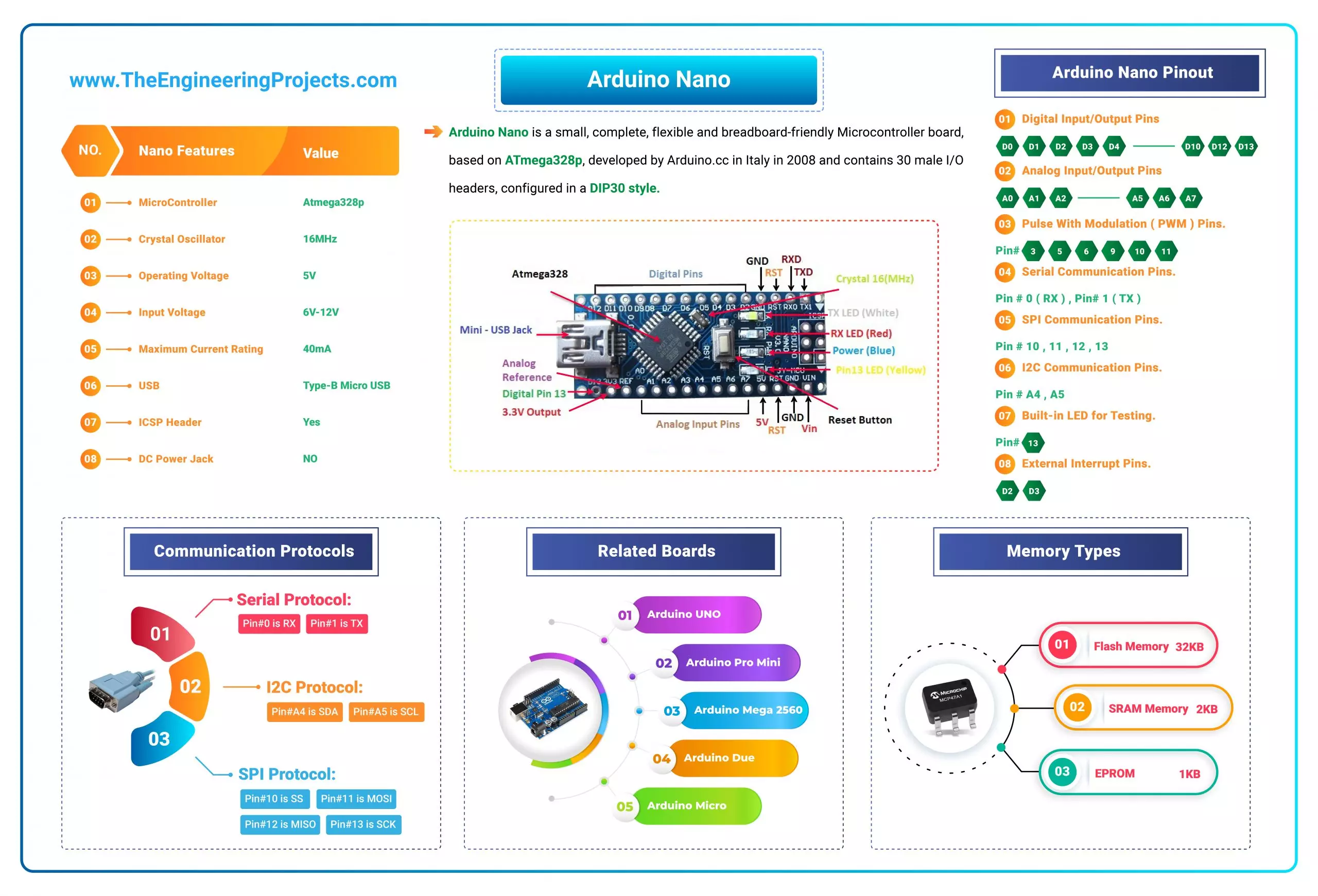
- Here's the table showing important features of Arduino Nano:
| No. | Nano Features | Value |
|---|---|---|
| 1 | Microcontroller | Atmega328p |
| 2 | Crystal Oscillator | 16MHz |
| 3 | Operating Voltage | 5V |
| 4 | Input Voltage | 6V-12V |
| 5 | Maximum Current Rating | 40mA |
| 6 | USB | Type-B Micro USB |
| 7 | ICSP Header | Yes |
| 8 | DC Power Jack | No |
- Here's the quick overview of Arduino Nano Pinout:
| No. | Pin Number | Pin Description |
|---|---|---|
| 1 | D0 - D13 | Digital Input / Output Pins. |
| 2 | A0 - A7 | Analog Input / Output Pins. |
| 3 | Pin # 3, 5, 6, 9, 10, 11 | Pulse Width Modulation ( PWM ) Pins. |
| 4 | Pin # 0 (RX) , Pin # 1 (TX) | Serial Communication Pins. |
| 5 | Pin # 10, 11, 12, 13 | SPI Communication Pins. |
| 6 | Pin # A4, A5 | I2C Communication Pins. |
| 7 | Pin # 13 | Built-In LED for Testing. |
| 8 | D2 & D3 | External Interrupt Pins. |
- Arduino Nano offers three types of communications protocols, shown in the below table:
| No. | Communication Protocols | Description |
|---|---|---|
| 6 | Serial Port | 1 (Pin#0 is RX, Pin#1 is TX). |
| 7 | I2C Port | 1 (Pin#A4 is SDA, Pin#A5 is SCL). |
| 8 | SPI Port | 1 (Pin#10 is SS, Pin#11 is MOSI, Pin#12 is MISO, Pin#13 is SCK). |
- Here's the memory details present in Arduino Nano:
| No. | Memory Type | Value |
|---|---|---|
| 7 | Flash Memory | 32KB |
| 8 | SRAM Memory | 2KB |
| 7 | EEPROM | 1KB |
Compare with other Arduino Boards:
- Arduino UNO
- Arduino Pro Mini
- Arduino Mega 2560
- Arduino Due
- Arduino Micro
- Arduino Lilypad
- Arduino YUN
Introduction to Arduino Nano

- Arduino Nano is a small, complete, flexible and breadboard-friendly Microcontroller board, based on ATmega328p, developed by Arduino.cc in Italy in 2008 and contains 30 male I/O headers, configured in a DIP30 style.
- Arduino Nano Pinout contains 14 digital pins, 8 analog Pins, 2 Reset Pins & 6 Power Pins.
- It is programmed using Arduino IDE, which can be downloaded from the Arduino Official site.
- Arduino Nano is simply a smaller version of Arduino UNO, thus both have almost the same functionalities.
- It comes with an operating voltage of 5V, however, the input voltage can vary from 7 to 12V.
- Arduino Nano's maximum current rating is 40mA, so the load attached to its pins shouldn't draw a current more than that.
- Each of these Digital & Analog Pins is assigned with multiple functions but their main function is to be configured as Input/Output.
- Arduino Pins are acted as Input Pins when they are interfaced with sensors, but if you are driving some load then we need to use them as an Output Pin.
- Functions like pinMode() and digitalWrite() are used to control the operations of digital pins while analogRead() is used to control analog pins.
- The analog pins come with a total resolution of 10-bits which measures the value from 0 to 5V.
- Arduino Nano comes with a crystal oscillator of frequency 16 MHz. It is used to produce a clock of precise frequency using constant voltage.
- There is one limitation of using Arduino Nano i.e. it doesn't come with a DC power jack, which means you can not supply an external power source through a battery.
- This board doesn't use standard USB for connection with a computer, instead, it comes with Type-B Micro USB.
- The tiny size and breadboard-friendly nature make this device an ideal choice for most applications where the size of the electronic components is of great concern.
- Flash memory is 16KB or 32KB that all depends on the Atmega board i.e. Atmega168 comes with 16KB of flash memory while Atmega328 comes with a flash memory of 32KB. Flash memory is used for storing code. The 2KB of memory out of total flash memory is used for a bootloader.
- The SRAM memory of 2KB is present in Arduino Nano.
- Arduino Nano has an EEPROM memory of 1KB.
- You can download Arduino Nano Datasheet by clicking the below button:
- The following figure shows the specifications of the Arduino Nano board.
- It is programmed using Arduino IDE which is an Integrated Development Environment that runs both offline and online.
- No prior arrangements are required to run the board. All you need is a board, a mini USB cable and Arduino IDE software installed on the computer.
- USB cable is used to transfer the program from the computer to the board.
- No separate burner is required to compile and burn the program as this board comes with a built-in boot-loader.
Now, let's have a look at Arduino Nano Pinout in detail:
Arduino Nano Pinout
- The following figure shows the pinout of the Arduino Nano Board:

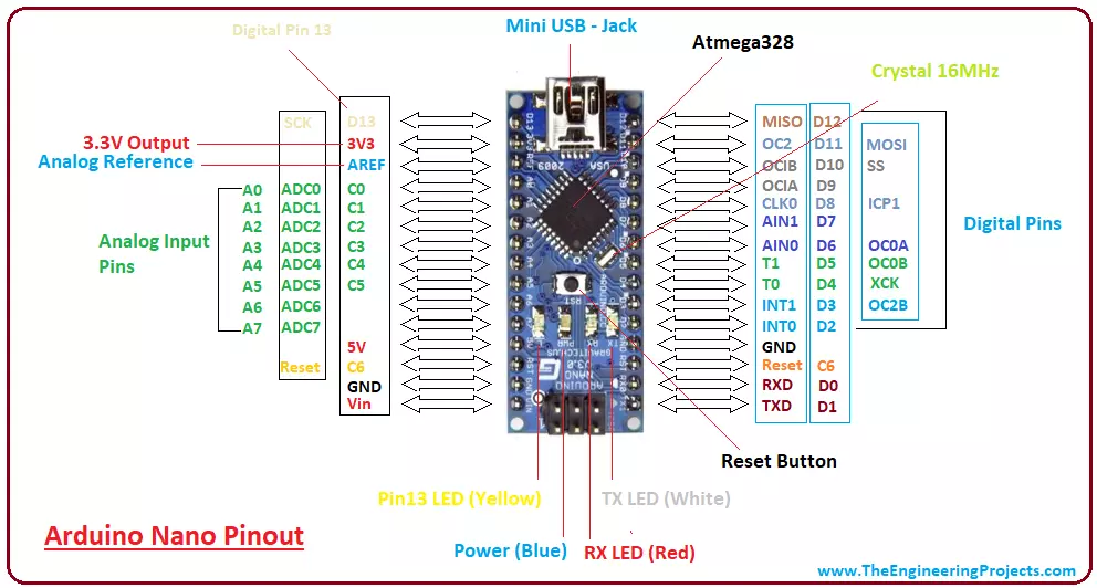
- Each pin on the Nano board comes with a specific function associated with it.
- We can see the analog pins that can be used as analog to digital converters, where A4 and A5 pins can also be used for I2C communication.
- Similarly, there are 14 digital pins, out of which 6 pins are used for generating PWM.
Let's have a look at the Arduino Nano Pinout in detail:
Arduino Nano Power Pins
- Vin: It is the input power supply voltage to the board when using an external power source of 7 to 12 V.

- 5V: It is a regulated power supply voltage of the board that is used to power the controller and other components placed on the board.

- 3V3: This is a minimum voltage generated by the voltage regulator on the nano board.

- GND Pin: These are the ground pins on the board.
- There are multiple ground pins on the board that can be interfaced accordingly when more than one ground pin is required.

Arduino Nano Function Pins
- Reset Pin: Arduino Nano has 2 reset pins incorporated on the board, making any of these Reset pins LOW will reset the microcontroller.

- Pin#13: A built-in LED is connected to pin#13 of the nano board.
- This LED is used to check the board i.e. it's working fine or not.
- AREF: This pin is used as a reference voltage for the input voltage.
Arduino Nano I/O Pins
- Analog Pins: There are 8 analog pins on the board marked as A0 - A7.
- These pins are used to measure the analog voltage ranging between 0 to 5V.

- Digital Pins: Arduino Nano has 14 digital pins starting from D0 to D13.
- These digital pins are used for interfacing third-party digital sensors and modules with Nano board.
- PWM Pins: Arduino Nano has 6 PWM pins, which are Pin#3, 5, 6, 9, 10 and 11. (All are digital pins)
- These pins are used to generate an 8-bit PWM (Pulse Width Modulation) signal.
- External Interrupts: Pin#2 and 3 are used for generating external interrupts normally used in case of emergency, when we need to stop the main program and call important instructions.
- The main program resumes once interrupt instruction is called and executed.
Nano Pinout for Communication Protocols
- Serial Pins: These pins are used for serial communication where:
- Pin#0 is RX used for receiving serial data.
- Pin#1 is Tx used for transmitting serial data.

- SPI Protocol: Four pins 10(SS->Slave Select), 11(MOSI -> Master Out Slave In), 12(MISO -> Master In Slave Out) and 13(SCK -> Serial Clock) are used for SPI (Serial Peripheral Interface) Protocol.
- SPI is an interface bus and is mainly used to transfer data between microcontrollers and other peripherals like sensors, registers, and SD cards.
- I2C Protocol: I2C communication is developed using A4 and A5 pins, where A4 represents the serial data line (SDA) which carries the data and A5 represents the serial clock line (SCL) which is a clock signal, generated by the master device, used for data synchronization between the devices on an I2C bus.

Arduino Nano Programming & Communication
- The Nano board comes with the ability to set up communication with other controllers and computers.
- The serial communication is carried out by the digital pins, Pin 0(Rx) and Pin 1(Tx) where Rx is used for receiving data and Tx is used for the transmission of data.
- The serial monitor is added to the Arduino IDE, which is used to transmit textual data to or from the board.
- FTDI drivers are also included in the software which behaves as a virtual com port to the software.
- The Tx and Rx pins come with an LED which blinks as the data is transmitted between FTDI and USB connection to the computer.
- Arduino Software Serial Library is used for carrying out serial communication between the board and the computer.
- Apart from serial communication the Nano board also supports I2C and SPI communication. The Wire Library inside the Arduino Software is accessed to use the I2C bus.
- The Arduino Nano is programmed by Arduino Software called IDE which is a common software used for almost all types of board available. Simply download the software and select the board you are using.
- Uploading code to Arduino Nano is quite simple, as there's no need to use any external burner to compile and burn the program into the controller and you can also upload code by using ICSP (In-circuit serial programming header).
- Arduino board software is equally compatible with Windows, Linux or MAC, however, Windows are preferred to use.
Arduino Uno Vs Arduino Nano
- Both Arduino Uno and Arduino Nano come with the same functionality with little difference in terms of PCB layout, size and form factor.
- Arduino Uno is a microcontroller board based on Atmega328 and comes with 14 digital I/O pins out of which 6 are PWM. There are 6 analog pins incorporated into the board. This board comes with everything required to support the microcontroller like a USB connection, a Power jack, a 16MHz oscillator, a reset button and an ICSP header. You don't require an extra peripheral with the board to make it work for automation.
- It is a complete ready-to-use device that requires no prior technical skills to get hands-on experience with it. You can power it by using a DC power jack, battery or simply plug it into the computer using a USB cable to get started.
- Arduino Nano is small and compact as compared to Arduino Uno. It lacks the DC power jack and comes with Mini USB support instead of regular USB. Also, the Nano board comes with two extra analog pins i.e. 8 pins as compared to 6 analog pins in the Uno board. Nano board is breadboard friendly while Uno board lacks this property.
- However, both devices run at 5V, come with a current rating of 40mA and 16MHz of the clock frequency.
Applications of Arduino Nano
Arduino Nano is a very useful device that comes with a wide range of applications and covers less space as compared to other Arduino boards. Breadboard-friendly nature makes it stand out from other boards. The following are the main applications of Arduino Nano:- Engineering Students' Projects.
- Medical Instruments
- Industrial Automation
- Android Applications
- GSM Based Projects
- Embedded Systems
- Automation and Robotics
- Home Automation and Defense Systems
- Virtual Reality Applications
That's all for today. I hope you have got a clear idea about the Nano board. However, if still you feel skeptical or have any questions, you can approach me in the comment section below. I'd love to help you according to the best of my knowledge and expertise. Feel free to keep us updated with your valuable feedback and suggestions, they help us provide you quality work that resonates with your requirements and allows you to keep coming back for what we have to offer. Thanks for reading the article.


