Hello everyone! I hope you all will be absolutely fine and having fun. Today, I am going to give you a detailed Introduction to ATmega328. ATmega328 is an Advanced Virtual RISC (AVR) microcontroller. It supports 8-bit data processing. ATmega-328 has 32KB internal flash memory.
ATmega328 has 1KB Electrically Erasable Programmable Read-Only Memory (EEPROM). This property shows if the electric supply supplied to the micro-controller is removed, even then it can store the data and can provide results after providing it with the electric supply. Moreover, ATmega-328 has 2KB Static Random Access Memory (SRAM). Other characteristics will be explained later. ATmega 328 has several different features which make it the most popular device in today's market. These features consist of advanced RISC architecture, good performance, low power consumption, real timer counter having separate oscillator, 6 PWM pins, programmable Serial USART, programming lock for software security, throughput up to 20 MIPS etc. Further details about ATmega 328 will be given later in this section.
Note:
Here's the link to download the Atmega328 datasheet, although after reading this article you won't need it. :)
Moreover, I have also given the link to a reliable online source from where you can buy it easily.
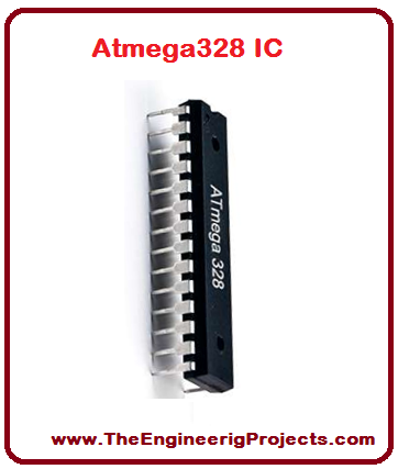
ATmega328 is an 8-bit, 28-Pin AVR Microcontroller, manufactured by Microchip, follows RISC Architecture and has a flash-type program memory of 32KB.
Atmega328 is the microcontroller, used in basic Arduino boards i.e Arduino UNO, Arduino Pro Mini and Arduino Nano.
It has an EEPROM memory of 1KB and its SRAM memory is 2KB.
It has 8 Pins for ADC operations, which all combine to form PortA ( PA0 - PA7 ).
It also has 3 built-in Timers, two of them are 8 Bit timers while the third one is 16-Bit Timer.
You must have heard of Arduino UNO, UNO is based on atmega328 Microcontroller. It's UNO's heart. :)
It operates ranging from 3.3V to 5.5V but normally we use 5V as a standard.
Its excellent features include cost-efficiency, low power dissipation, programming lock for security purposes, real timer counter with separate oscillator.
ATmega-328 is an AVR Microcontroller having twenty-eight (28) pins in total.
All of the pins in chronological order, are listed in the table shown in the figure given below.
Now let's have a look at the pinout of Atmega328 in detail:
ATmega328 Pinout
Through the pinout diagram, we can understand the configurations of the pins of any electronic device, so you are working on any Engineering Project then you must first read the components' pinout.
ATmega328 pinout diagram is shown in the figure given below:
ATmega328 Pins Description
Functions associated with the pins must be known in order to use the device appropriately.
ATmega-328 pins are divided into different ports which are given in detail below.
VCC is a digital voltage supply.
AVCC is a supply voltage pin for analog to digital converter.
GND denotes Ground and it has a 0V.
Port A consists of the pins from PA0 to PA7. These pins serve as an analog input to analog to digital converters. If analog to digital converter is not used, portA acts as an eight (8) bit bidirectional input/output port.
Port B consists of the pins from PB0 to PB7. This port is an 8 bit bidirectional port having an internal pull-up resistor.
Port C consists of the pins from PC0 to PC7. The output buffers of port C has symmetrical drive characteristics with source capability as well high sink.
Port D consists of the pins from PD0 to PD7. It is also an 8 bit input/output port having an internal pull-up resistor.
All of the AVR ports are shown in the figure given below.
AREF is an analog reference pin for analog to digital converter.
So this was the brief of all the pins in the ATmega328 AVR micro-controller.
ATmega328 Architecture
An architecture of a device presents information about the particular device.
ATmega-328 architecture is shown in the figure given below.
ATmega328 Memory
ATmega 328 has three types of memories, named:
Flash Memory: 32KB. It is a Programmable Read-Only Memory (ROM). It is a nonvolatile memory.
SRAM: 2KB. Stands for Static Random Access Memory. It is a volatile memory i.e. data will be removed after removing the power supply.
EEPROM: 1KB. Stands for Electrically Erasable Programmable Read-Only Memory.
AVR memory spaces are shown in the figure given below.
ATmega328 Registers
ATmega-328 has thirty-two (32) General Purpose (GP) registers.
These all of the registers are part of Static Random Access Memory (SRAM).
All the registers are given in the figure shown below.
ATmega328 Packages
The different versions of the same device are denoted by the different packages of that device.
Each package has different dimensions, in order to differentiate easily.
ATmega 328 packages are given in the table shown in the figure given below.
ATmega328 Block Diagram
The Block diagram shows the internal circuitry and the flow of the program of any device.
ATmega 328 block diagram is shown in the figure given below.
ATmega328 Features
To perform any task we can select a device on the basis of its features. i.e whether its features match to obtain the desired results or not.
Some of the main features of an AVR Microcontroller ATmega328 are shown in the table given in the figure below.
ATmega328 and Arduino
ATmega328 is the microcontroller used in the Arduino UNO board.
When we upload code in Arduino UNO, it's actually uploaded in the Atmega328 Microcontroller.
A software driver called bootloader is pre-installed in the flash memory of the Atmega328 microcontroller, which makes it compatible with Arduino IDE.
AVR Atmega328 attached on Arduino is shown in the figure given below:
ATmega328 and Arduino Pins
ATmega328 pins are connected to the corresponding pins of Arduino.
Their connectivity with each other is shown in the pinout diagram shown in the figure given below.
The encircled section analog pins consist of the Arduino pins which are connected to the corresponding AVR micro-controller ATmega-328 pins.
I have written both of the pins in front of each other, it will help to understand easily.
If you want to work on this Arduino board then you must try these Arduino Projects for Beginners, they will help to get your hands on Arduino.
Applications of Atmega328
A complete package including ATmega 328 and Arduino can be used in several different real-life applications.
Once you are confirmed that everything's correct then design its circuitry on Wero Board or PCB (Printed Circuit Board) and you have your project ready. :)
The tutorial Introduction to ATmega328 has the presented a detailed discussion on the basic use of ATmega 328. I have completely provided the entire necessary details about the use of an AVR micro-controller. If you have any problems, you can ask us in the comments anytime. Our team is always here to help you guys. I will share other amazing topics with all of you in my upcoming tutorials. So, till then take care :)
sir,
you have mentioned above that atmega328 have 4 port - portA, portB, portC, portD each have 8 pins which mean 8x4 = 32 but atmega328 has 28 pins. As clearly shown in the pinout diagram that there is no portA on the microcontroller.