
Variable 4 Way Traffic Light:
As you all already know the importance of traffic lights and their usage has solved a number of traffic problems, traffic is becoming denser on each road in the whole world by the hour. This leads us to consider traffic density at such roads as well. A number of different solutions have been developed in recent times to help with this problem such as roundabouts. This is done so to ensure the safety of vehicles on road and of people walking on pedestrian walks. With the world going towards automation and autonomous systems, this is the right time to switch traffic lights to an autonomous traffic light system too and make the system intelligent.
Software to Install:
We will be going through how to make an autonomous traffic system by using Arduino as a microcontroller. However, we’re not making an actual system rather we will be making a simulation of the said traffic system on a circuit simulating software Proteus. So make sure you already have the latest version of Proteus installed on your PCs and laptops. If not, you should first install the Proteus Software by following the embedded link. Proteus is open database software, meaning people can easily make their own circuit simulating libraries for the software and can easily integrate those libraries. This helps in making the software versatile and easy to use. You can easily add your own components or download libraries of components and place them within the software.
To start working with this project, you need to install and include the following libraries on your Proteus software:
- Arduino Library for Proteus: This library includes all the microcontroller-based programming boards made by the company Arduino.cc. This allows you to program on the Arduino software and after that, you can see the implementation of this code in Proteus simulation.
- LCD Library for Proteus: LCDs are displays that can be used to display text or values being used in a certain code. These LCDs come in two sizes, namely a 16x2 and 24x4. LCDs are controlled by the Arduino board.
- Ultrasonic Sensor Library for Proteus: Since we are using an ultrasonic sensor as well in this project for which Proteus does not have a built-in component, you would need to download its library as well.
Project Overview:
This is a smart 4-way traffic light system. The pedestrian lights work such that whenever a certain traffic light is green its opposite pedestrian lights turn on. An addition of ultrasonic sensors have been made in the traffic light sequence. One ultrasonic sensor is placed at each traffic light. Each ultrasonic sensor controls the time of their respective green traffic light. When the ultrasonic sensor output is high, the traffic light opens for one second, when the ultrasonic sensor output is intermediate the traffic light opens for two seconds and when the ultrasonic sensor output is low the traffic lights open for 3 seconds.
The main components and their use in this project is given below:
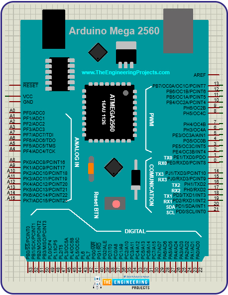
- Arduino Mega: We have used Arduino mega in this project and recommend using an Arduino mega as well. This is because there are about 40 digital pins required to perform communication between the microcontroller and only an Arduino Mega fulfills that requirement.
- Traffic Light Module: Proteus provides an in-built module for simulating traffic lights and we will use this instead of using RGB lights to create a better effect.
- Ultrasonic Module: This module is not built-in, but information to integrate this module with Proteus has been given above. This module has a test pin in order to simulate it and works just like real life.
- LCD: Liquid crystal display will be used to show the time in which the traffic light remains on.
Components Needed:
- Arduino Mega
- Traffic Lights
- Green and Red LEDs
- Variable resistors
- LCD
- Ultrasonic Sensor
Component Details:
We will go through the details of some of the important components being used in this project.
Arduino Mega:
Arduino is an open-source programmable board that serves as a microcontroller and processes information based upon inputs and gives information to actuators in terms of output. Arduino Mega is based upon the chip ATmegaGA2560 and has 53 digital I/O pins.
LCD:
Liquid Crystal Displays used in electronics are of two basic sizes, 16x2 and 24x2. These represent the number of columns and rows of the LCD. Each pixel can store one character in it. It is also known as a character LCD. It comes equipped with a backlight. The intensity or glow of the backlight can be controlled by attaching a potentiometer at specified pins.
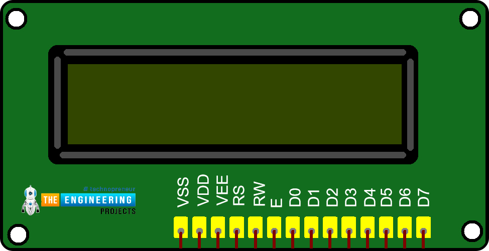
Figure 2: LCD display
Ultrasonic Sensor:
An ultrasonic sensor uses SONAR technology to identify objects. It is basically used to find the distance of objects from the sensor. The ultrasonic sensor works by sending out ultrasonic waves and when these waves or parts of waves hit an object, they are reflected backward and the time from their propagation to their return is then noted. This time is then converted into the distance because we already know the speed by which those waves are traveling.
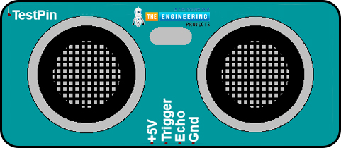
Figure 3: Ultrasonic Sensor
Proteus Simulation of Variable Traffic Lights:
In order to simulate this project on Proteus software, we will first make the circuit diagram on Proteus. After that, we will write our code on Arduino IDE software and integrate it with the circuit made in Proteus.
Open Proteus and open a new project. Import the following components in your Proteus worksheet.
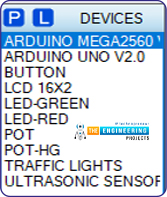
Place the component in your worksheet as illustrated in the figure below:
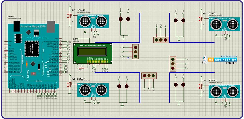
Figure 5: Placement of components
After placing the components, make the connections as follows:
- Connect 0,1 and 2 digital pins of Arduino to red, yellow and green of traffic light 1 respectively.
- Connect 3,4 and 5 digital pins of Arduino to red, yellow and green of traffic light 2 respectively.
- Connect 6,7 and 8 digital pins of Arduino to red, yellow and green of traffic light 3 respectively.
- Connect 9,10 and 11 digital pins of Arduino to red, yellow and green of traffic light 4 respectively.
- Connect 12and 13 digital pins of Arduino to red and green LEDs of pedestrian light 1 respectively.
- Connect 14 and 15 digital pins of Arduino to red and green LEDs of pedestrian light 2 respectively.
- Connect 16 and 17 digital pins of Arduino to red and green LEDs of pedestrian light 3 respectively.
- Connect 18 and 19 digital pins of Arduino to red and green LEDs of pedestrian light 4 respectively.
- Ground the negative terminals of all LEDs.
- Connect one end of a variable resistor to the Vss pin of LCD.
- Connect the other end of the variable resistor to the input.
- Connect the input pin of the variable resistor with the Vee pin of LCD.
- Ground the RW pin of LCD.
- Connect RS pin of LCD to 22 digital pin of Arduino.
- Connect E pin of LCD to 23 digital pin of Arduino.
- Connect D4, D5, D6 and D7 pin of LCD to 24, 25, 26 and 27 digital pins of LCD respectively.
- Connect the test pin of ultrasonic sensors to their respective potentiometers.
- Connect the trigger pin and echo pin of the ultrasonic sensor of traffic light 1 to 28 and 29 digital pins of Arduino respectively.
- Connect the trigger pin and echo pin of the ultrasonic sensor of traffic light 2 to 30 and 31 digital pins of Arduino respectively.
- Connect the trigger pin and echo pin of the ultrasonic sensor of traffic light 3 to 32 and 33 digital pins of Arduino respectively.
- Connect the trigger pin and echo pin of the ultrasonic sensor of traffic light 4 to 34 and 35 digital pins of Arduino respectively.
With this, your circuit connections are complete and we will now move on to the firmware setup of this circuit.
Arduino Code:
We have divided the Arduino code in 3 segments:
- Declaration Code
- Void setup
- Void loop
We will look at these sections separately now.
Declaration Code:
The first step in the code is the declaration of variables that we will utilize in our program. At first is the declaration of ultrasonic sensor pins and setting them up with their respective pins of Arduino board. The syntax of this code is as follows.
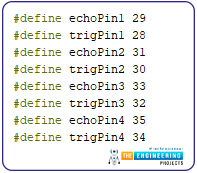
Figure 6: Ultrasonic declaration code
Now we will include the library of LCD into our Arduino program, you can download this library from within the software. After that we will declare the LCD by defining the LCD pins. The syntax for which is as follows:

In the next step, we will declare traffic light variables and define their Arduino pins.
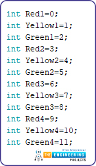
Figure 8: Traffic light variable declaration
Now, we will declare the variables of pedestrian LEDs and then allot them their Arduino pins being used in the circuit.
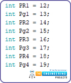
Figure 9: Declaration of pedestrian LEDs
Now, there are two variables being used for each ultrasonic sensor for the calculation of their distance and time duration. We will declare those variables now.
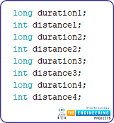
Figure 10: Declaration of variables being used for calculations
Void Setup:
Void setup is the part of Arduino program that only runs once, in this section the program that only needs to run once is put, such as declaring pins as output pins or input pins.
Only the echo pins of ultrasonic sensor are input pins while all other pins are going to be output pins for this project.
We will first set up ultrasonic pins as follows:
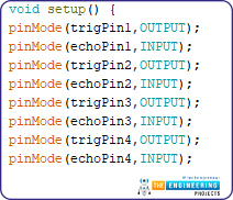
Now we will declare traffic light pins as output pins. The syntax for this is given as follows:
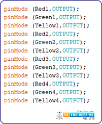
Figure 12: Setup of Traffic light Pins as Output
Now we will setup our pedestrian LEDs.
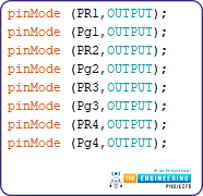
Figure 13: Setup of Pedestrian LEDs as Output
Now we will initialize our LCD, this basically tells the microcontroller to start the LCD and give power to it. The syntax is given below.

Figure 14: Initializing LCD
Void Loop:
This part of Arduino Program runs in a loop and consists of the main code of the program in which all the calculations are being done.
In the first part of the program, we will set the trigger pin of the first ultrasonic sensor to low and high. This would generate a pulse and send out a wave. After that we will read a pulse input from the echo pin. This will give us the duration in which the wave was propagated and returned. After that we will calculate the distance from the duration of the wave.
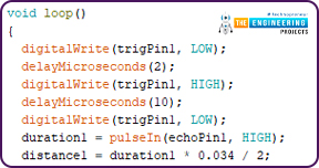
Figure 15: Syntax of 1st Ultrasonic Sensor
This distance calculation is for our first traffic light. Now we will use the if loop to check our distance value.

If the value falls between our set limit for the loop, the signal will turn green for three seconds. This will also be displayed on the LCD.
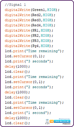
Figure 17: Arduino Code
After that in our if loop, the yellow lights 1 and 2 will turn on to indicate transition.
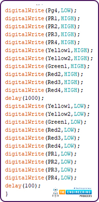
Figure 18: Arduino Code
Now we will use the if loop to check our distance value.
If the value falls between our set limit for the loop of intermediate traffic, the signal will turn green for two seconds. This will also be displayed on the LCD.
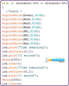
Figure 19: Arduino Code
After that in our if loop, the yellow lights 1 and 2 will turn on to indicate transition.
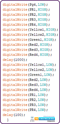
Now we will use the if loop to check our distance value again.
If the value falls between our set limit for the loop of low traffic, the signal will turn green for one second. This will also be displayed on the LCD.
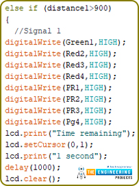
Figure 21: Arduino Code
After that in our if loop, the yellow lights 1 and 2 will turn on to indicate transition.
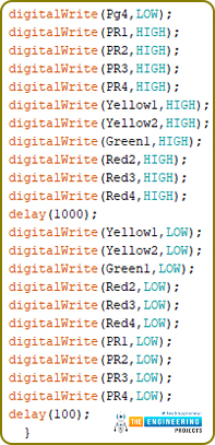
Figure 22: Arduino Code
Now we will set the trigger pin of the second ultrasonic sensor to low and high. This would generate a pulse and send out a wave. After that we will read a pulse input from the echo pin. This will give us the duration in which the wave was propagated and returned. After that we will calculate the distance from the duration of the wave.
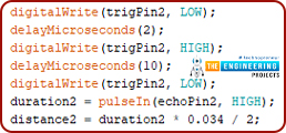
Figure 23: Arduino Code
This distance calculation is for our Second traffic light. Now we will use the if loop to check our distance value.

Figure 24: Arduino Code
If the value falls between our set limit for the loop, the signal will turn green for three seconds. This will also be displayed on the LCD.
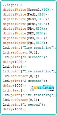
After that in our if loop, the yellow lights 2 and 3 will turn on to indicate transition.
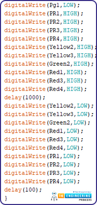
Figure 26: Arduino Code
Now we will use the if loop to check our distance value.
If the value falls between our set limit for the loop of intermediate traffic, the signal will turn green for two seconds. This will also be displayed on the LCD.
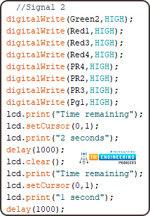
Figure 27: Arduino Code
After that in our if loop, the yellow lights 2 and 3 will turn on to indicate transition.
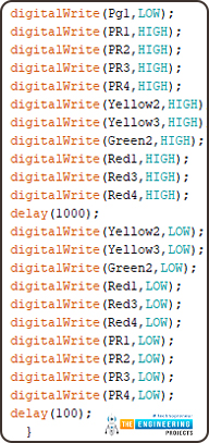
Figure 28: Arduino Code
Now we will use the if loop to check our distance value again.
If the value falls between our set limit for the loop of low traffic, the signal will turn green for one second. This will also be displayed on the LCD.
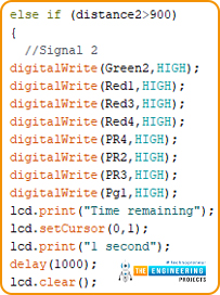
Figure 29: Arduino Code
After that in our if loop, the yellow lights 2 and 3 will turn on to indicate transition.
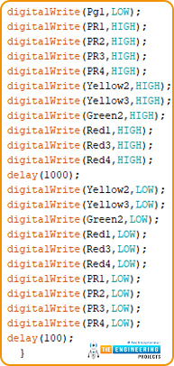
Now we will set the trigger pin of the third ultrasonic sensor to low and high. This would generate a pulse and send out a wave. After that, we will read a pulse input from the echo pin. This will give us the duration in which the wave was propagated and returned. After that we will calculate the distance from the duration of the wave.
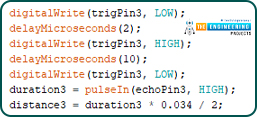
Figure 31: Arduino Code
This distance calculation is for our third traffic light. Now we will use the if loop to check our distance value.

Figure 32: Arduino Code
If the value falls between our set limit for the loop, the signal will turn green for three seconds. This will also be displayed on the LCD.
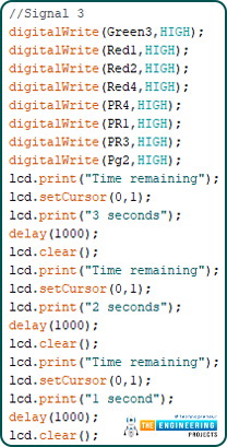
Figure 33: Arduino Code
After that in our if loop, the yellow lights 3 and 4 will turn on to indicate transition.
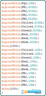
Figure 34: Arduino Code
Now we will use the if loop to check our distance value.
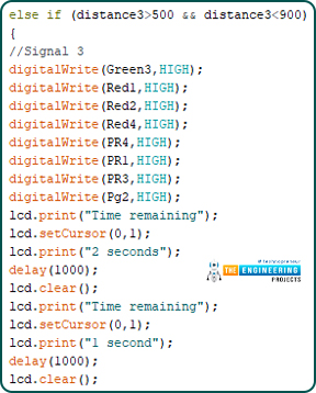
If the value falls between our set limit for the loop of intermediate traffic, the signal will turn green for two seconds. This will also be displayed on the LCD.
After that in our if loop, the yellow lights 3 and 4 will turn on to indicate transition.
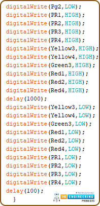
Figure 36: Arduino Code
Now we will use the if loop to check our distance value again.
If the value falls between our set limit for the loop of low traffic, the signal will turn green for one second. This will also be displayed on the LCD.
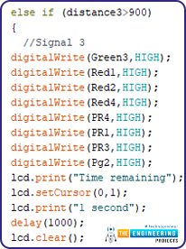
Figure 37: Arduino Code
After that in our if loop, the yellow lights 3 and 4 will turn on to indicate transition.

Figure 38: Arduino Code
Now we will set the trigger pin of the fourth ultrasonic sensor to low and high. This would generate a pulse and send out a wave. After that, we will read a pulse input from the echo pin. This will give us the duration in which the wave was propagated and returned. After that, we will calculate the distance from the duration of the wave.

Figure 39: Arduino Code
This distance calculation is for our fourth traffic light. Now we will use the if loop to check our distance value.

If the value falls between our set limit for the loop, the signal will turn green for three seconds. This will also be displayed on the LCD.

Figure 41: Arduino Code
After that in our if loop, the yellow lights 4 and 1 will turn on to indicate transition.

Figure 42: Arduino Code
Now we will use the if loop to check our distance value.
If the value falls between our set limit for the loop of intermediate traffic, the signal will turn green for two seconds. This will also be displayed on the LCD.

After that in our if loop, the yellow lights 4 and 1 will turn on to indicate transition.

Figure 44: Arduino Code
Now we will use the if loop to check our distance value again.
If the value falls between our set limit for the loop of low traffic, the signal will turn green for one second. This will also be displayed on the LCD.

Figure 45: Arduino Code
After that in our if loop, the yellow lights 4 and 1 will turn on to indicate transition.

Figure 46: Arduino Code
Results/Working:
At first, after writing the code, generate its hex file and put that hex file on the Arduino board on your Proteus software. After that, run the simulation. The results of the simulation are shown below thoroughly.
At first, when sensor one gives the output within 500 cm, the traffic light will turn on for one second only.

Figure 47: Simulation Results
However, if the sensor one value is between 500 and 900 cm, the traffic light 1 will be green for 2 seconds with the LCD displaying the remaining time.

Figure 48: Simulation Results
If the sensor values are above 900 cm, then the lights will be green for 3 seconds.

When the sensor two gives the output within 500 cm, traffic light 2 will turn on for one second only.

Figure 50: Simulation Results
However, if the sensor two value is between 500 and 900 cm, the traffic light 2 will be green for 2 seconds with the LCD displaying the remaining time.

Figure 51: Simulation Results
If the sensor values are above 900 cm, then the lights will be green for 3 seconds.

Figure 52: Simulation Results
When sensor three gives the output within 500 cm, traffic light 3 will turn on for one second only.

However, if the sensor three value is between 500 and 900 cm, the traffic light 3 will be green for 2 seconds with the LCD displaying the remaining time.

Figure 54: Simulation Results
If the sensor values are above 900 cm, then the lights will be green for 3 seconds.

Figure 55: Simulation Results
When sensor four gives the output within 500 cm, traffic light 4 will turn on for one second only.

Figure 56: Simulation Results
However, if the sensor four value is between 500 and 900 cm, the traffic light 4 will be green for 2 seconds with the LCD displaying the remaining time.

Figure 57: Simulation Results
If the sensor values are above 900 cm, then the lights will be green for 3 seconds.

Figure 58: Simulation Results
Phew! I know that this was an extremely long project, but that is a part of an engineer’s life. Multiple receptions and running recurring patterns smoothly requires skill and patience only an engineer can possess. I hope you guys made it through. Kudos to your nerves of steel. Thanks for reading.


 Arduino
 zoyebella
 1 Comments


 2.3k
2.3k
 953
953
 921
921
 2.1K
2.1K


