


How to Upload Bootloader in Atmega328


Hello friends! Today we will install the Arduino bootloader on an ATmega328P using a second Arduino Uno as the programmer. This is useful when replacing the socketed processor on a classic Uno or restoring a compatible target whose serial bootloader has been erased.
We will follow the original two-board arrangement: board B is the working programmer, and board A contains the target processor. Giving the boards separate roles helps prevent a common mistake, which is changing settings for one board while accidentally programming the other.
The title uses the familiar ATmega328 family name, but the standard classic Uno configuration targets the ATmega328P. Read the marking on your chip before starting. An ATmega328, ATmega328P and ATmega328PB are different device selections; a similar name is not sufficient reason to ignore a signature mismatch.
What Is an Arduino Bootloader?
A bootloader is a small program stored in part of the microcontroller's flash memory. On a classic Uno, it allows suitable firmware to be received through the serial interface and written into the application area.
It is not a Windows driver, and it does not translate Arduino source code inside the chip. The compiler on your computer still converts the sketch into machine code. The bootloader handles one method of transferring that compiled program to flash.
The Uno's USB interface is a separate part of the board. Burning the ATmega328P bootloader does not repair a broken USB connector or automatically reprogram the USB-to-serial controller. Keep the host connection and target-programming problems separate.
A microcontroller can run an application without a serial bootloader when programmed through a suitable external programmer. The bootloader is convenient for normal USB serial uploads, but it is not what makes the processor capable of executing Arduino-compiled code.
Bootloader Upload and Sketch Upload Are Different Operations
| Operation | Communication path | Main purpose |
|---|---|---|
| Normal Uno sketch upload | Computer, USB serial interface and existing bootloader | Replace the application sketch |
| Burn Bootloader | Computer, programmer and target ISP signals | Prepare target configuration and install its bootloader |
| Upload Using Programmer | Computer, programmer and target ISP signals | Program an application directly |
The Burn Bootloader operation is not simply an ordinary upload with a different filename. The board platform defines a programming sequence that includes relevant fuse and lock settings as well as the bootloader image. Treat it as an operation that erases the existing application.
If the target contains an important program or stored configuration, arrange an appropriate backup before changing it. Do not assume EEPROM will survive every erase workflow; preservation depends on the device configuration and programming operation.
Our Arduino HEX-file tutorial explains the compiled application output. A saved application HEX and an installed bootloader serve different purposes and should be identified separately in your project records.
Hardware and Software Requirements
- One working classic Uno to act as the programmer.
- One compatible target Uno board containing the intended ATmega328P.
- Short jumper wires for the ISP signals and power.
- A working USB data cable for the programmer.
- Arduino IDE with the Arduino AVR Boards platform installed.
- Optional reset-suppression capacitor if the programmer's automatic reset interferes.
This procedure concerns the classic AVR Uno, including the Uno R3. It is not a bootloader-recovery recipe for the Uno R4 or every board sold under the Arduino name. Those products can use different processors and programming interfaces.
If you are replacing a socketed DIP processor, disconnect all power first. Match the package notch and pin-one orientation to the socket, straighten pins carefully and check that none fold underneath the chip. A soldered surface-mount processor cannot be replaced by simply pulling it out.
The Microchip ATmega328P product page provides the device documentation. Use the datasheet for your actual package when working outside a complete Uno board; DIP pin numbers and board-header labels are different numbering systems.
Step 1: Turn Board B into the Programmer
Start with only board B connected to the computer. This keeps the first upload unambiguous and avoids powering the target through loose jumper wires while preparing the programmer.
- Open Arduino IDE and select the classic Arduino Uno board.
- Select the serial port belonging to board B.
- Open the ArduinoISP example from the examples menu.
- Upload it with the normal Upload button.
- Wait for a successful upload before connecting the target.
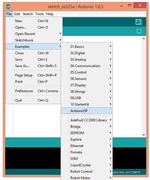
The example's menu location can vary slightly with the IDE version; it is commonly grouped under 11.ArduinoISP. The retained screenshot shows the older interface, but the purpose remains the same: put the programmer firmware onto the working board.
Do not use Burn Bootloader at this stage. We are uploading an ordinary sketch to board B through its existing bootloader. Once that sketch runs, it can accept programming commands from the computer and generate ISP transactions for board A.
Keep ArduinoISP installed on board B during the rest of the procedure. Accidentally uploading Blink or another example to it removes its programmer function until ArduinoISP is uploaded again.
Step 2: Wire the Programmer to the Target
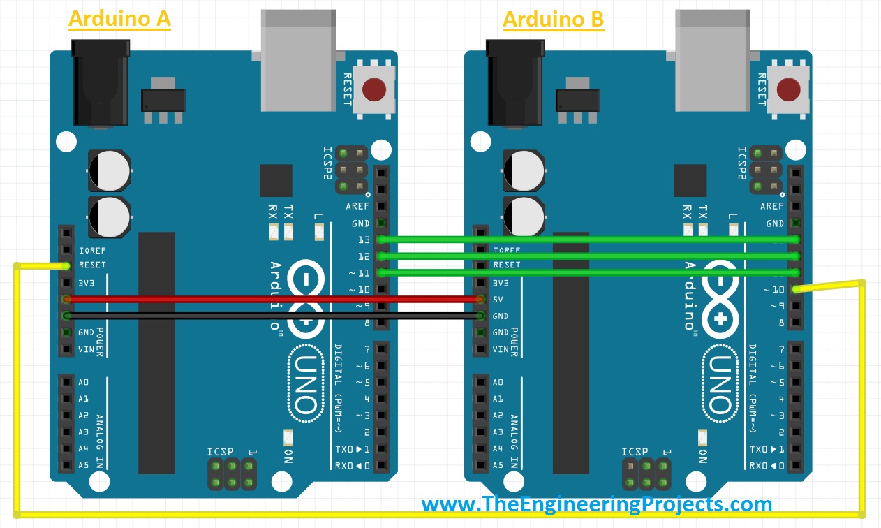
Disconnect board B's USB cable before making the connections. Remove shields or external circuits that could load the target's SPI or reset signals. Then connect the boards as follows.
| Programmer board B | Target board A | Purpose |
|---|---|---|
| D10 | RESET | Holds the target in programming mode |
| D11, MOSI/COPI | D11, MOSI/COPI | Programming data from programmer to target |
| D12, MISO/CIPO | D12, MISO/CIPO | Programming data from target to programmer |
| D13, SCK | D13, SCK | Programming clock |
| 5 V | 5 V | Target power in this two-Uno arrangement |
| GND | GND | Common electrical reference |
Unlike a UART connection, MOSI and MISO are not crossed between these two boards. The signal names already describe the controller's output and input roles. Connect the matching SPI functions.
The target's RESET must go to the programmer's D10, not the programmer's RESET pin. Board B needs to keep executing ArduinoISP while it controls board A's reset state.
For this simple arrangement, power the target from board B and leave the target USB and barrel supply disconnected. If your target is separately powered, design that arrangement explicitly: share the required ground, use compatible signal voltages and avoid connecting competing supply outputs together.
Arduino's bootloader installation guide also shows an ICSP-header connection method. When using those headers, identify their orientation carefully and still route the target RESET to the programmer's controlling pin.
A standard Uno R3 also has programming connections associated with its USB-interface microcontroller. Identify the ICSP header belonging to the ATmega328P rather than choosing whichever six-pin header is nearest the cable. Programming the USB-interface chip is a separate task with different firmware. When in doubt, the explicitly labelled D11, D12, D13 and RESET connections in the table make the target signal path easier to trace.
Step 3: Select the Target and Programmer Settings
Reconnect board B to the computer. The port remains board B's port, because the computer communicates with the programmer. The target does not need its own USB connection during the bootloader operation.
Now select the board definition that matches board A. In our example, both boards are classic Unos, so the visible board selection stays Arduino Uno. When using different programmer and target boards, the board choice must change to the target after ArduinoISP is uploaded.
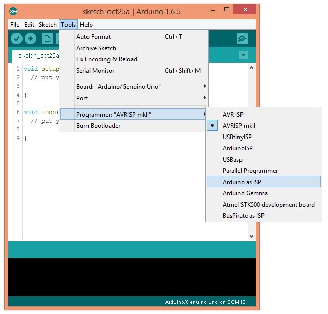
Select Arduino as ISP in the Programmer menu. Do not substitute a similarly named option such as ArduinoISP: the names can refer to different programmer protocols or products.
| Setting during Burn Bootloader | What it identifies |
|---|---|
| Board | The target processor configuration |
| Processor or clock options, when present | The intended target variant |
| Port | The working programmer board connected to the computer |
| Programmer | The protocol used to communicate with that programmer |
These settings describe different parts of the process. Writing them down before a difficult recovery is useful: it prevents a random sequence of menu changes from obscuring what was actually attempted.
Step 4: Burn the Bootloader
Enable verbose programming output if you want a detailed record, then choose Tools, Burn Bootloader. Leave the wires and power connections undisturbed until the IDE reports completion.
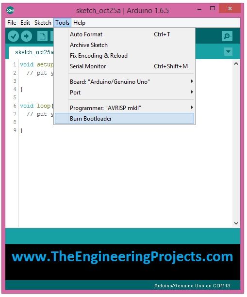
The exact progress display and completion message depend on the IDE version. Do not judge success only from flashing LEDs or from waiting a fixed number of seconds. Read the result, including any device-signature, erase, fuse or verification errors.
If the operation succeeds, disconnect power before removing the ISP wiring. The target is now ready for the next step: a normal sketch upload through its own USB connection.
If it fails, save the first meaningful error and the selected settings. Repeating the same operation without inspecting the cause can hide an intermittent wire fault, but it does not repair an incorrect target definition.
Understand the Clock and Fuse Configuration
Fuse bits configure hardware behavior such as the clock source, startup timing and bootloader arrangement. They are not the replaceable wire fuses used for overcurrent protection.
The standard Uno definition assumes an ATmega328P running at 16 MHz with the appropriate board clock circuit. The Arduino AVR board definitions identify the target processor, build frequency, bootloader file and associated settings.
A blank processor may initially use a slower internal clock. If you program Uno settings onto a bare chip that has no suitable external clock circuit, it may stop responding normally after those settings take effect. That is not necessarily a damaged chip; the selected clock source may simply be absent.
Using a complete compatible target Uno avoids having to assemble the clock and support circuitry in this beginner workflow. For a breadboard target, supply the correctly configured oscillator, decoupling, reset wiring and all required power pins before applying a board definition.
Do not copy fuse-byte values from an unrelated tutorial. Some settings can disable ordinary reset-based ISP access, and recovery may require a different programming method. Let a verified board definition configure the intended target rather than experimenting with arbitrary bytes.
How Much Flash Does the Bootloader Use?
The ATmega328P has 32 KiB of flash, which is 32768 bytes. The standard Uno platform configuration allows 32256 bytes for the application, leaving 512 bytes for its bootloader allocation.
The calculation is 32768 - 32256 = 512 bytes. This is a flash-memory allocation, not a deduction from the processor's 2048 bytes of SRAM. Different bootloaders or board definitions can reserve a different amount.
The Optiboot project documents the small bootloader family used in the classic Uno workflow. The exact bootloader supplied by your installed board package is the version that matters when reproducing a particular setup.
Record the board-package version along with the selected target. A successful burn under one configuration should not be described as proof that every bootloader build or clock setting will work on the same hardware.
Step 5: Upload a Normal Sketch to Board A
Remove the programming connections with power disconnected, then connect board A directly to the computer. Select the target Uno and its own serial port. Open Blink or another simple example and use the normal Upload button.
The Programmer menu does not need to be changed back to AVRISP for an ordinary classic Uno serial upload. Arduino's programmer-selection documentation distinguishes operations that use this setting from normal upload behavior.
A successful normal upload checks more than the bootloader-programming transaction alone: it also exercises the target's USB serial path and reset-to-bootloader behavior. Observe the sketch's expected output rather than assuming the installation is finished because the burn command completed.
If normal upload fails but ISP programming worked, investigate the target's USB interface, selected serial port, reset circuit and serial pins. These are different from the SPI wires used for burning the bootloader.
Troubleshooting Common Programming Errors
The programmer does not respond
Confirm that ArduinoISP is actually running on board B, the correct port is selected and another program is not holding that port open. Close a serial terminal that is using the programmer before starting the operation.
On some Uno programmer setups, opening the serial connection causes an unwanted automatic reset. A commonly used remedy is a 10 microfarad capacitor between the programmer's RESET and GND, positive lead to RESET, installed after uploading ArduinoISP. This is on board B, not across the target's reset-control signal. Remove it before attempting another normal sketch upload to the programmer.
The device signature is wrong
Check the target marking, power, common ground, RESET connection and SPI wiring. Repeated all-zero or all-one responses can indicate a communication failure rather than a useful chip identity.
A consistent signature for a different device deserves investigation. Do not use an override merely to make the error disappear. The programming tool uses the device selection to determine memory layout and programming operations.
A slow or blank target cannot be programmed
The ISP clock must suit the target's operating clock. Microchip's ISP programming guidance specifies a clock below one quarter of the target clock for the described AVR ISP operation.
For a 1 MHz target, that means an ISP clock below 250 kHz; a conservative 125 kHz setting leaves margin. The programmer firmware determines how to select that rate. Do not assume an arbitrary uploader option changes the clock of every ArduinoISP implementation.
Programming works only when wires are moved
Shorten the connections, inspect loose sockets and remove external loads from the programming pins. A successful attempt after touching a wire suggests an unreliable connection, not a stable recovery.
The target disappears after changing fuses
Review the intended clock source and reset/programming configuration. Restore the required clock hardware where appropriate and use a documented recovery procedure. Repeated normal USB uploads cannot fix a target whose selected clock is absent.
Review the Completed Setup
At the end of this process, board B should still contain ArduinoISP unless you deliberately replace it, while board A should contain its intended bootloader and subsequently uploaded test sketch. Label the programmer if you plan to keep using it.
For the project record, note the target chip, board definition, clock, board-package version and successful programming result. Keep the wiring diagram with the programmer so the D10-to-RESET connection is not forgotten next time.
You can then move on to our Arduino projects for beginners. The related Arduino Proteus library is useful for application simulation, but loading firmware into a simulated model is not the same operation as configuring a physical chip's bootloader and fuses.
Frequently Asked Questions
Do I need to burn the bootloader before every sketch?
No. Once the correct bootloader is installed, normal serial uploads can replace the application without repeating the ISP setup.
Can I use a chip marked ATmega328 without the P?
Use a supported definition for that exact device. Do not assume the standard Uno's ATmega328P selection accepts it or bypass the signature check.
Does burning the bootloader fix every upload error?
No. A faulty cable, wrong port, damaged USB bridge, missing clock or incorrect reset circuit can prevent uploading even with a valid bootloader.
Can I program the chip without any bootloader?
Yes, through an appropriate programmer and target configuration. Direct application programming can erase the serial bootloader, so choose that workflow deliberately.
Why is only one board connected to USB during the burn?
The computer talks to board B, and board B programs board A. In this tutorial, board B also provides the target supply, avoiding an unnecessary second power connection.

Tags


I found the below message. pls solve me
Arduino: 1.8.3 (Windows 10), Board: "Arduino/Genuino Uno"
avrdude: Yikes! Invalid device signature.
Double check connections and try again, or use -F to override
this check.
Error while burning bootloader.
This report would have more information with
"Show verbose output during compilation"
option enabled in File -> Preferences.
THANK YOU SOOOOO MUCH!!!! I've been trying to figure this out for years!! It finally worked!!! Now. On to build a robot with my children! :) You are AWESOME!!
It works obly with ATMEGA328P and not ATMEGA328.
You must change all atmega328 from this post to atmega328P since arduino IDE does not support plain and simple atmega328 - PU, it supports atmega328P - PU or just atmega328P.
Just for clarification:
The ATMega328 is a microcontroller chip, the theoretical reference design.
ATMega328-PU is the microcontroller in a DIP package.
ATMega328 SMD is the other, surface mount version of the 328, with 2 extra analogs.
ATMega328P is the ATMega reference design with the picoPower low voltage running capability, available in PU and SMD versions
ATMega328P-PU is the most common ATMega found on Arduino UNOs and other boards. This is possibly the easiest to work with when making your own duino.
ATMega328P SMD is the chip found on Lilypad and Nano boards and boasts two extra analogs.
I hope this helps to make your post better
avrdude: Expected signature for ATmega328P is 1E 95 0F
Double check chip, or use -F to override this check.
Error while burning bootloader.
how to fix this problem sir . i am a student of E&TC , please help me.
Comments
4