


Arduino 74HC165 Interfacing: Increase Input Pins


Arduino 74HC165 Interfacing
- I will design a Proteus Simulation of Arduino 74HC165 Interfacing, I have given the files for download at the end of this tutorial, but I would recommend you to design it so that you could learn.
- I will connect simple Logic buttons with this shift register and will read their status on the Serial Port.
- So, first of all design a simple Proteus Simulation as shown in below figure.
- I have used Arduino UNO and have connected Virtual Terminal so that we could have a look at Serial data.
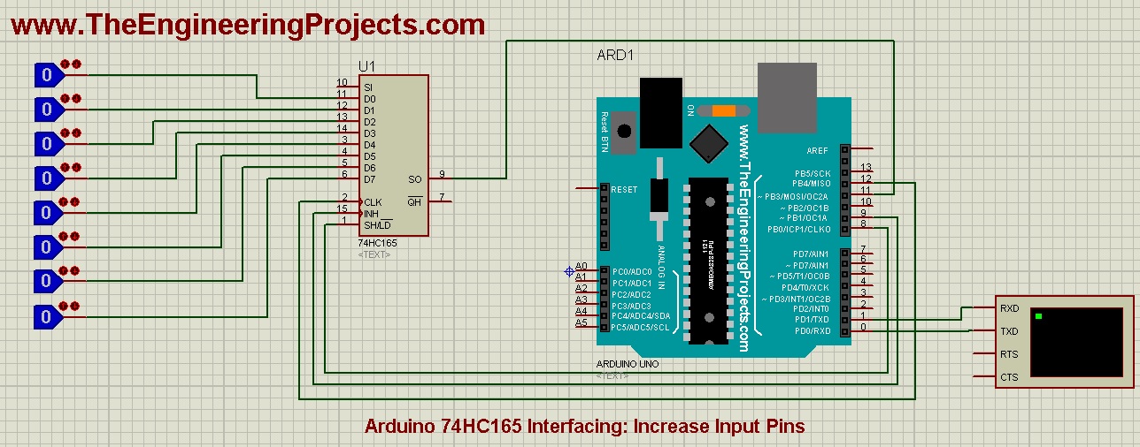
- As you can see in the above figure that I have connected four pins between Arduino and 74HC165, which are:
- Pin # 8 of Arduino ==> Shift (SH) of shift register.
- Pin # 9 of Arduino ==> Clock Enable (CE) of shift register.
- Pin # 11 of Arduino ==> Serial OUT (SO) of shift register.
- Pin # 12 of Arduino ==> Clock (CLK) of shift register.
- Now open you Arduino software and copy paste the below code in it:
#define NUMBER_OF_SHIFT_CHIPS   1
#define DATA_WIDTH   NUMBER_OF_SHIFT_CHIPS * 8

int LoadPin    = 8;
int EnablePin  = 9;
int DataPin    = 11;
int ClockPin   = 12;

unsigned long pinValues;
unsigned long oldPinValues;

void setup()
{
    Serial.begin(9600);

    pinMode(LoadPin, OUTPUT);
    pinMode(EnablePin, OUTPUT);
    pinMode(ClockPin, OUTPUT);
    pinMode(DataPin, INPUT);

    digitalWrite(ClockPin, LOW);
    digitalWrite(LoadPin, HIGH);

    pinValues = read_shift_regs();
    print_byte();
    oldPinValues = pinValues;
}

void loop()
{
    pinValues = read_shift_regs();

    if(pinValues != oldPinValues)
    {
        print_byte();
        oldPinValues = pinValues;
    }

}

unsigned long read_shift_regs()
{
    long bitVal;
    unsigned long bytesVal = 0;

    digitalWrite(EnablePin, HIGH);
    digitalWrite(LoadPin, LOW);
    delayMicroseconds(5);
    digitalWrite(LoadPin, HIGH);
    digitalWrite(EnablePin, LOW);

    for(int i = 0; i < DATA_WIDTH; i++)
    {
        bitVal = digitalRead(DataPin);
        bytesVal |= (bitVal << ((DATA_WIDTH-1) - i));

        digitalWrite(ClockPin, HIGH);
        delayMicroseconds(5);
        digitalWrite(ClockPin, LOW);
    }

    return(bytesVal);
}

void print_byte() {
  byte i;

  Serial.println("*Shift Register Values:*\r\n");

  for(byte i=0; i<=DATA_WIDTH-1; i++)
  {
    Serial.print("P");
    Serial.print(i+1);
    Serial.print(" ");
  }
  Serial.println();
  for(byte i=0; i<=DATA_WIDTH-1; i++)
  {
    Serial.print(pinValues >> i & 1, BIN);

    if(i>8){Serial.print(" ");}
    Serial.print("  ");

  }

  Serial.print("\n");
  Serial.println();Serial.println();

}
- The code is quite simple but let me give you a quick explanation of it.
- First of all, I have assigned names to all 4 pins of 74HC165 connected with Arduino.
- Function read_shift_regs() is used to read the eight input pins of 74HC165 and print_byte() function is used to display that data on Serial Monitor.
- So get your hex file from Arduino software and upload it in Proteus software.
- Run your Proteus simulation and if everything goes fine then you will get results as shown in below figure:
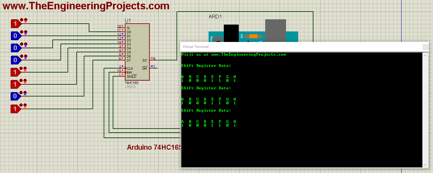
- If you change any input of your shift register then you will get the new value on your Virtual Terminal.
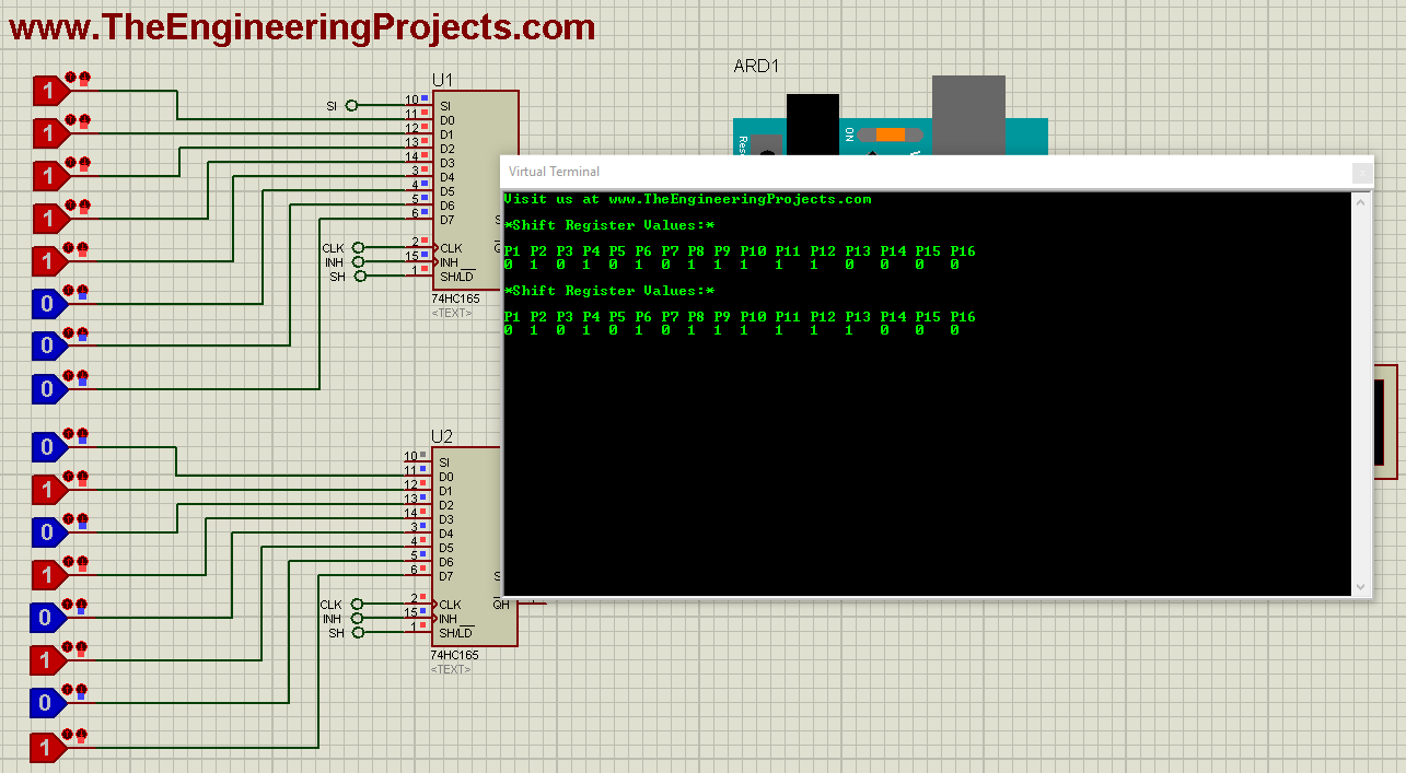
- Now let's add another 74HC165 and increase our input pins by 16.
- So, design a simple circuit as shown in below figure:
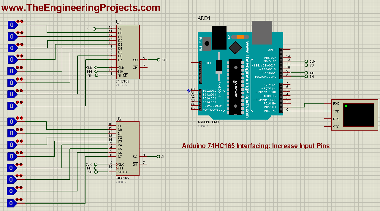
- Now, in the above code, simply change the first line and make #define NUMBER_OF_SHIFT_CHIPS 2.
- Simply changes 1 to 2, as we are using 2 shift registers now.
- Now get your hex file and run the Proteus simulation.
- Here's the output of our 16 increased inputs:
- That's how you can easily interface multiple 74HC165 chips with your Arduino board and can increase the input options.
- You can download these Proteus simulations and code for Arduino 74HC165 Interfacing by clicking the below button:
[dt_default_button link="https://www.theengineeringprojects.com/ArduinoProjects/Arduino 74HC165 Interfacing.rar" button_alignment="default" animation="fadeIn" size="medium" default_btn_bg_color="" bg_hover_color="" text_color="" text_hover_color="" icon="fa fa-chevron-circle-right" icon_align="left"]Download Proteus Simulation & Code[/dt_default_button]
- You should also have a look at this video in which I have shown How to run these simulations:

Just wanted to point out that the Serial in pin should be connected to ground, unless it's being used, to prevent unwanted behavior and also to protect the circuit against ESD. Usually older type of TTL circuits aren't that sensitive to ESD, but the AC(T), HC(T) families are since they're members of the CMOS family. Even they do have some ESD protection already built-in, you can never be too careful, especially if you're soldering one of these circuits without sockets, and it can also be very difficult to detect once mounted. It's common practice to never leave open pins, inputs in particular, unless otherwise specified in the datasheet of a circuit.
Comments
3