


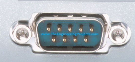
What is Serial Port


Hello friends! Today we will learn what a serial port is, how it transfers information and how to connect serial devices without confusing their electrical interfaces. We will begin with bits and bytes, then examine UART framing, the familiar nine-pin RS-232 connector and the settings needed for a useful conversation between two devices.
You may encounter a serial port as a connector on an instrument, a small header on a microcontroller board or a COM port that appears when a USB adapter is plugged into a computer. These can provide similar software interfaces while using very different voltages and wiring. Understanding that distinction is the first step toward a reliable connection.
The original article introduced the connector and its applications. This revised tutorial keeps that progression while correcting an important misconception: serial communication sends bits in sequence, not necessarily one bit per second. We will calculate the actual payload rate and finish with a small local loopback experiment you can use to investigate a suitable adapter.
What Is a Serial Port?
A serial port is an interface through which data is transmitted as a sequence of bits. In ordinary embedded-system discussions, the term often refers to an asynchronous UART connection or a computer interface built around it. A UART is a universal asynchronous receiver-transmitter. It converts parallel bytes inside a processor into timed serial frames and reconstructs received frames into bytes.
Serial describes an ordering of information, not a particular connector. USB, SPI and I2C also transfer serial information, but their signaling and protocols differ from an asynchronous UART link. You cannot connect two devices merely because both are described as serial.
A computer's COM port name is a software identifier. COM7 does not tell us whether the external connection is RS-232, logic-level UART or a USB device implementing a virtual serial interface. Likewise, a Linux device path identifies an operating-system endpoint, not the voltage safe to apply to its connector.
Separate the Four Layers of a Connection
| Layer | Question to answer | Example |
|---|---|---|
| Physical connection | Which pins carry which signals? | DE-9 connector or labeled board header |
| Electrical interface | What voltages and drivers are used? | 3.3 V UART, RS-232 or differential RS-485 |
| Character framing | How is each byte timed and framed? | 9600 bit/s with eight data bits and one stop bit |
| Application protocol | What do the bytes mean? | A newline-terminated temperature reading |
This separation makes troubleshooting much easier. A correct command string cannot repair reversed wiring, and a correctly wired link cannot interpret an unsupported command. Verify each layer before moving to the next.
How a UART Sends a Byte
An asynchronous UART normally has a transmit signal, TX, and a receive signal, RX. Asynchronous means that the two endpoints do not share a separate bit-clock wire. Each endpoint uses its own timing source and agrees in advance on the nominal transmission rate and frame format.
For a common 8N1 format, a frame contains one start bit, eight data bits, no parity bit and one stop bit. The start transition lets the receiver establish timing for that character. Data bits commonly travel least significant bit first. The stop interval returns the line to its idle condition before another character begins.
At logic-level UART pins, idle is normally HIGH and the start bit is LOW. RS-232 line drivers translate and invert these electrical levels. This is why a waveform viewed at the microcontroller pin looks different from the corresponding waveform on an RS-232 cable.
Baud Rate and Useful Data Rate
Baud is the number of signaling symbols per second. With ordinary binary UART signaling, one symbol carries one bit, so the numerical baud rate and bit rate are equal. That equality should not be generalized to every modulation system.
For 8N1, each eight-bit payload byte occupies ten bit periods. The ideal maximum character rate is therefore:
Payload bytes per second = bit rate / (1 start + 8 data + 1 stop).
At 9600 bit/s, the upper limit is 960 bytes per second. At 115200 bit/s, it is 11,520 bytes per second. A 32-byte message at 9600 bit/s takes at least 32 × 10 / 9600 = 0.0333 seconds on the wire. Software delays, acknowledgments and gaps between messages increase the complete transaction time.
Adding an even-parity bit changes 8N1 to 8E1 and requires eleven bit periods per byte. For a 100-byte message at 9600 bit/s, the minimum wire time becomes about 114.6 ms instead of 104.2 ms. These calculations help you choose a sensible response timeout instead of guessing a value that is shorter than the transfer itself.
Parity Detects Some Errors, Not Every Error
Even parity chooses a parity bit so the total number of ones in the protected data and parity bit is even. Odd parity makes that total odd. A parity mismatch can reveal some transmission errors, but parity does not reliably detect every multi-bit corruption and does not repair a damaged message.
A packet protocol can add a checksum or CRC, length field and sequence number. Those mechanisms address different problems: corruption, message boundaries and duplicate or missing transactions. They are not automatically supplied simply because a UART is present.
UART Voltage Levels and RS-232
A microcontroller UART often uses logic levels related to its supply, such as 0 V and 3.3 V. A traditional RS-232 interface uses positive and negative line voltages. For data signals, a valid negative voltage represents the mark or logical-one state, while a valid positive voltage represents space or logical zero. The region near zero is not a valid guaranteed data state.
Do not connect an RS-232 transmitter directly to an Arduino input. An appropriate transceiver is needed between the cable and the logic pins. Devices in the MAX232 and MAX3232 families perform that conversion, but their supply ranges and required external components differ. Follow the exact part's datasheet; TI provides the MAX3232 electrical specifications and typical circuit.
A USB-to-UART adapter with TXD, RXD and GND pins usually does not provide RS-232 voltage levels. Conversely, a USB-to-RS-232 adapter with a nine-pin connector should not be treated as a bare logic-level adapter. Read the product specification rather than deciding from the cable color or the COM-port name.
What About RS-485?
RS-485 uses differential signaling between a pair of conductors and can support a shared bus with suitable transceivers and protocol control. It is an electrical interface rather than a complete command language. A UART can supply the characters that an RS-485 transceiver sends, but bus direction, termination and device addressing still need attention.
Do not substitute an RS-485 adapter into an RS-232 connection without redesigning the interface. Even differential terminal labels can differ between manufacturers, so consult the documentation at both ends. The correct question is which conductor must be more positive for a defined receiver state, not whether two products happen to print the same letter.
The Nine-Pin RS-232 Connector
The common nine-pin connector is technically a DE-9, although DB9 is widely used as a product label. It contains nine contacts, not eight. A standard PC-style data terminal equipment connection uses the following assignments. Always check whether you are looking into the mating face or at the wiring side, since the apparent layout is mirrored.
| Pin | Signal | Direction at a conventional DTE port | Purpose |
|---|---|---|---|
| 1 | DCD | Input | Data carrier indication from communication equipment |
| 2 | RXD | Input | Received serial data |
| 3 | TXD | Output | Transmitted serial data |
| 4 | DTR | Output | Terminal-ready indication |
| 5 | Signal ground | Reference | Signal voltage reference |
| 6 | DSR | Input | Equipment-ready indication |
| 7 | RTS | Output | Request-to-send or flow-control function |
| 8 | CTS | Input | Clear-to-send flow-control indication |
| 9 | RI | Input | Ring indication on modem-style equipment |
NI's serial connector reference lists the corresponding connector assignments. These names do not mean that every instrument uses every signal. A simple device may communicate with TXD, RXD and signal ground while leaving the modem-control functions unused.
CTS does not carry the payload data, and DSR does not select the baud rate. Payload travels on the data lines. Control signals communicate readiness or other defined conditions according to the device and driver configuration.
DTE, DCE and Null-Modem Cables
Data terminal equipment and data communication equipment have complementary signal roles. A suitable straight-through cable can connect the expected DTE and DCE pair. Two DTE ports generally require a null-modem arrangement that crosses transmit and receive, with any necessary control-signal wiring determined by the equipment.
For two compatible logic-level UART devices, the usual arrangement is the first device's TX connected to the second device's RX, the second TX connected to the first RX, and a common ground. That statement assumes compatible voltage levels and non-isolated interfaces. Do not connect two actively driven TX outputs together.
A three-wire cable can be sufficient when hardware flow control is disabled at both ends and the receiving software can keep up. If a device requires RTS/CTS, omitting those conductors can leave transmission paused. Randomly shorting control pins may hide a configuration error rather than providing a reliable interface.
Configure Both Endpoints Consistently
Start with the receiving device's manual. Record the bit rate, data-bit count, parity, stop bits and flow-control setting. A terminal configured for 9600 8N1 cannot be expected to interpret a device sending 19200 7E1 correctly.
Hardware flow control uses dedicated signals to manage data movement. Software flow control commonly reserves XON and XOFF control bytes. If those byte values are valid binary payload, enabling software flow control without considering the protocol can cause unexpected pauses or lost information.
Line endings are a separate application setting. One instrument might expect a carriage return, another a line feed, and another the two-byte CRLF sequence. A perfectly received command can be ignored if its terminator is wrong. Check whether the software adds a terminator automatically before adding another one yourself.
Text and Binary Are Not Interchangeable
The decimal number 65 can be represented as a single binary byte with value 65, or as the two text characters '6' and '5'. In ASCII, byte value 65 represents the letter A. A receiver must know which representation the sender intends.
For example, an Arduino binary write of one byte differs from printing a decimal value. Printing a line also adds a line ending. See Arduino's Serial.write reference and Serial.println reference when choosing an encoding.
For multi-byte binary values, also define byte order, signedness and units. A two-byte field representing 250 could mean 250 degrees, 25.0 degrees or a raw ADC count. The UART moves bytes; the application protocol gives those bytes meaning.
Try a Local Loopback Test
A loopback test sends data back into the same adapter's receiver. It can help establish that the computer, driver and adapter data path work before another device is introduced. It does not prove that the eventual remote device, cable length or application protocol is correct.
- Disconnect the adapter from the external instrument.
- Identify its electrical interface from its documentation.
- For a standard DTE RS-232 DE-9 port, connect TXD pin 3 to RXD pin 2. For a suitable logic-level UART adapter, connect its labeled TXD to RXD instead.
- Leave power pins and unrelated contacts alone. Check the adapter's documented loopback procedure if it requires additional signals.
- Open the correct port with flow control disabled and local echo disabled.
- Send a recognizable text pattern and check that the received bytes match.
NI describes this diagnostic approach in its serial loopback guide. Local echo must be disabled because a terminal can otherwise display your typing even when nothing has returned from the adapter.
A Bounded Python Example
Install the pySerial package in your chosen Python environment and replace COM7 with your adapter's actual port. This example is specifically for the isolated loopback arrangement, not a command to send to an unknown machine. It limits the read duration and compares bytes exactly.
import time
import serial

port_name = "COM7"
payload = b"Serial loopback 0123456789\r\n"

with serial.Serial(port_name, 9600, timeout=0.1,
                   write_timeout=1, rtscts=False,
                   xonxoff=False, dsrdtr=False) as port:
    port.reset_input_buffer()
    count = port.write(payload)
    received = bytearray()
    deadline = time.monotonic() + 2.0
    while len(received) < len(payload) and time.monotonic() < deadline:
        received.extend(port.read(len(payload) - len(received)))
    print("Written:", count)
    print("Received:", bytes(received))
    print("Exact match:", bytes(received) == payload)
The context manager closes the port when the block finishes. The timeout prevents a missing response from causing an endless wait. The pySerial introduction explains port opening, timeouts and byte-oriented reads. The code is a reader-run diagnostic example; no physical loopback result is claimed here.
Troubleshooting a Serial Connection
| Symptom | Likely area to investigate | Useful next step |
|---|---|---|
| Port cannot open | Wrong name, permissions or another program holding it | Close competing terminals and identify the connected adapter |
| Unreadable characters | Framing mismatch or electrical problem | Confirm settings and observe the actual signal |
| No transmitted data | Flow control or application behavior | Check CTS requirements and whether bytes are actually queued |
| Valid text but no response | Command syntax or terminator | Compare exact transmitted bytes with the device manual |
| Occasional missing messages | Buffer overrun, scheduling or wiring noise | Reduce rate and log sequence numbers and errors |
Read operations may return only part of a message. Keep a receive buffer until the defined delimiter or complete length arrives, with a maximum permitted size and a timeout. A successful write generally confirms that software accepted data for transmission; it does not prove that the remote application acted on it.
If retries can repeat an action, design them carefully. Requesting a temperature again is different from issuing a second motor movement. Sequence numbers and explicit acknowledgments let an application distinguish a repeated command from a new one. This is a protocol design problem rather than a baud-rate setting.
Applications and Practical Review
Keep a connection record containing the adapter model, connector view, wiring map, electrical levels, frame format and a known working request and response. Save a byte dump as well as the readable text. That record makes it possible to reproduce a result after a cable or computer is replaced, without relying on remembered terminal settings.
Serial interfaces remain useful in test instruments, industrial controllers, embedded debugging, navigation receivers and equipment configuration. Some machines use legacy connectors, while newer products expose a USB virtual port. A standard computer monitor normally uses a video interface, so do not assume that an ordinary RS-232 port provides display video.
The strengths of UART-style communication are modest hardware requirements and easy inspection of a simple byte stream. Its limitations include electrical compatibility requirements, limited buffering and the need to define application-level framing. For a reliable design, document the entire connection instead of writing only “connect serial.”
Frequently Asked Questions
Does serial mean one bit per second?
No. Bits are transferred sequentially, but the rate can be thousands or millions of bits per second depending on the supported hardware and configuration. Framing overhead reduces the useful payload rate.
Is every USB port a COM port?
No. USB supports many device classes and protocols. A COM port appears only when the operating system exposes a suitable serial interface through its driver.
Can I connect RS-232 directly to Arduino TX and RX?
No. Use a suitable RS-232 transceiver or an adapter that already provides compatible logic-level signals. Check voltage requirements before connecting anything.
Why do characters appear twice in a terminal?
Local echo and a returned echo can both be enabled. Disable local echo and determine whether the remote endpoint intentionally echoes received data before changing the wiring.
Does an acknowledgment prove a command was completed?
Only if the protocol defines it that way. An acknowledgment may mean received, queued or completed. Read the device's definition and use a separate completion response when required.

Comments
0