Hello friends, I hope you all are doing well. In today's tutorial, we are going to design a Home Security System using Arduino UNO in Proteus software. It's the most commonly designed engineering project, especially in electrical, electronics and mechatronics engineering. Normally engineering students design it as a semester project during their engineering course.
So, today we will design a home security system from scratch in Proteus software. I have given the complete project below to download but I would suggest you to design it on your own so that you could understand it better. So, let's get started:
Home Security System: Project Description
Before going into the detail, let's first download the complete Proteus Simulation with Arduino Code, by clicking the below button:
Let me first give you a detailed project description i.e. what we actually want to design? We want to build a Home Security Project, which should follow these security protocols:
Fire alarm: It should be able to detect the fire and sound an alarm to alert everyone at home.
Smoke alarm: It should detect the gas(smoke) and turn on the alarm(if detected).
The above-mentioned security protocols will be followed 24/7. Moreover, there will be two security modes in the project, named:
Secure Mode.
Normal Mode.
Let's have a look at both of these modes, one by one:
1. Secure Mode
This mode should be selected, when owners want to completely secure their home i.e. they are leaving home or while sleeping at night.
If the Secure Mode is selected, the project should follow the following security protocols:
Intruder Detection Alarm: It should detect the presence of any human being in the occupied premises.
Windows Security Alarm: If someone tries to break through the windows, the project should sound an alarm.
Door Security Alarm: If any intruder tries to break through the main door, it should again sound the alarm to alert everyone.
2. Normal Mode
This mode should be selected, when owners are at home and just want to take the basic security measures.
In this mode, only the Fire Alarm & Gas Alarm will work, while all other alarms will remain on standby.
Other Features
There should be an LCD, to display values of all parameters.
It should have a buzzer to generate an alarm, in case of emergency.
There should a Push Button to make switches between these security modes.
Here's the final simulation, which we are going to design in today's lecture:
So, these are our requirements, which we want to achieve in this Home Security Project. Now let's have a look at the components selected for this project:
Home Security System: Components Selected
Now let's have a look at the list of components, which I have selected for this Home Security Project. I will also briefly explain the purpose of using each component.
1. Arduino UNO
As clearly it's an Embedded Systems Project, so first of all we need to select a Microcontroller for our project.
As I have mentioned earlier, we will use the Arduino UNO Microcontroller board for designing this project.
Arduino UNO will act as the brain of the project and will control all sensors and modules.
2. Flame Sensor:
A flame sensor is used to detects the presence of fire.
The sensor basically consists of a photo-diode that detects the Infrared rays that emit from the fire. When it detects a fire, its output goes HIGH.
3. Gas Sensor (MQ-6)
MQ-6 Gas Sensor is used to detect the concentration of gases in the environment.
The sensor produces a potential difference proportional to the concentration of the particular gases.
The type of gas that it detects depends upon the material used in the sensor.
There are many gas sensors available in the market i.e. MQ-2, MQ-3, MQ-4 etc.
These sensors are available as ready-made modules for easy interfacing with the microcontroller.
4. PIR Sensor(HC-SR501)
HC-SR501 PIR sensor is used to detect any human being(intruder) in the Secure Mode.
It detects the IR radiations from the human movement & generates a pulse on its output.
The time period of the pulse could be varied by using the potentiometer on the sensor.
5. Vibration sensor(SW-420)
The SW-420 vibration sensor is used to detect any forced entry through windows.
In Secure Mode, if someone tries to open the window, the sensor will detect vibrations and will send a HIGH signal to the microcontroller.
6. Infrared Sensor
An infrared sensor will be placed at the door and someone tried to enter through that door, the sensor will detect it.
It consists of an IR transmitter and a photo-diode that are placed close to each other.
If any object movement occurs in front of the sensor, the IR rays hit the object and return back with a particular angle called incident angle.
This pulls the comparator output to ground or logic LOW.
7. LCD 20x4
LCD 20x4 will be used for displaying the values of all these sensors.
It will also display useful information i.e. which mode is selected.
8. Buzzer
A small 5V Buzzer is used to sound the alarm.
9. LM7805
LM7805 is a voltage regulator and is used to convert voltage from 12V to 5V.
Power sources(i.e. battery, adapter etc.) available are normally 12V, as it has become a standard.
Moreover, many components also operate at 12V like a buzzer or DC motor.
While microcontrollers and sensors work on 5V, so in Embedded projects, it's quite necessary to design a voltage regulator from 12V to 5V and in some cases 3.3V.
I normally prefer LM7805 for converting voltage from 12V to 5V.
10. Resistances(1kohm)
We need to use a few resistances of 1kohm.
11. Small LED
We will also use a small LED for power indication.
12. Capacitors(100uF)
We will also use few capacitors of 100uF, as it removes any noise/ripples.
So, these are the components, we are going to use for designing Home Security System. Now let's get started with designing the Proteus Simulation:
Proteus Simulation of Home Security System
As I have told you earlier, I am going to use Proteus software for designing this project. Proteus is an excellent simulation tool, where we will not only design the circuit of this project but will also test its output. I always design my programming algorithms on simulations as working on real hardware is too time-consuming. You should remove all your programming bugs in simulation and once confirmed then design your project in real hardware. So, let's start:
Install Proteus Libraries
Arduino boards & sensors' modules are not available in the Proteus components list.
So, first of all, we need to install these Proteus libraries:
Once you added all the libraries, now open your Proteus software.
Designing Circuit Diagram in Proteus
Now we need to design a circuit for our project, so select these components from Proteus Components Search Box.
First of all, let's design the voltage regulator circuit using LM7805, which will be simply converting the voltage from 12V to 5V.
As you can see in the above figure, I have used 12V Battery, while the output of LM7805 is showing 5V and I have also placed an LED for power indication.
LCD Interfacing with Arduino:
Next, we need to interface 20x4 LCD with Arduino UNO, so design the circuit as shown in the below figure:
Next, we need to interface five sensors with Arduino UNO, so let's add them to our Proteus simulation:
Sensors Interfacing with Arduino:
These are simple digital & analog sensors and are all powered up at 5V.
So, simply connect them as shown in the below figure:
The Flame Sensor is connected to pin A0 of Arduino UNO.
Gas Sensor is connected to pin A1 of Arduino UNO.
PIR Sensor is connected to pin A2 of Arduino UNO.
The Vibration Sensor is connected to pin A3 of Arduino UNO.
The Infrared Sensor is connected to pin A4 of Arduino UNO.
For simulation, ensure all hex files are uploaded to each sensor for proper working. You can upload the source code hex file to the Arduino, by pressing Ctrl+E or by right click --> Edit properties.
Buzzer & Push Button:
Finally, we need to add the Buzzer to sound the alarm in emergency cases, I have connected it to Pin A5 of Arduino UNO.
I have also connected a push-button for switching the modes, connected to Pin 7 of Arduino UNO, as shown in the below figure:
Here's the image of the complete Proteus Simulation for Home Security System:
Now let's design the Arduino programming code for Home Security Project:
Arduino Code for Home Security System
In the previous section, we have designed the Proteus simulation of the project, now let's design its Arduino Code to make it alive. Let's get started:
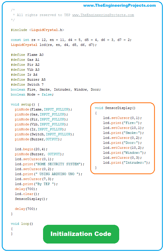
Initialization LCD Arduino Code
First of all, we need to define all our variables, as you can see in the code shown in the right figure.
I have included the Liquid Crystal Library, which is used to operate LCD.
Next, I have defined all my sensors to the respective pins and then initialized boolean variables for storing the output of sensors.
In the Setup loop, I have made the sensors' pins input pullup using the pinMode Arduino command.
Finally, displayed an initialization message on the LCD screen i.e. "Home Security System using Arduino UNO By TEP".
The message will display for around 1 second and then LCD will be cleared and the SensorDisplay function will be called, which will simply write sensors' names on the LCD screen.
Now compile your code and add the hex file in Arduino UNO and run your PRoteus simulation.
If everything goes fine, you will get results as shown in the below figure:
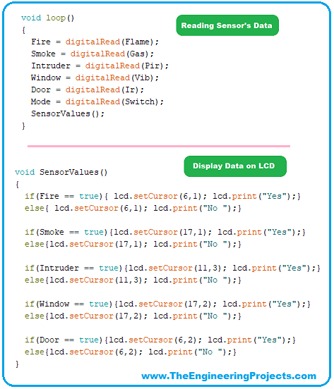
So far, we have just displayed the sensor's names, now let's read the sensors' data in the loop section:
Reading Sensors' Data
In the loop section, first of all, we need to read the sensors' data using the digitalRead command, as shown in the code.
After reading the sensor's data, I have called the SensorValues function, in which I have placed a check on each sensor's value and updated it on LCD.
It's quite straightforward code, if the sensor is giving HIGH output, I am displaying Yes on LCD and if it's LOW, I am simply printing No.
We haven't yet defined the modes, so the project will keep on reading the sensors and will display their respective value in the LCD.
As you can see in the below figure, if the TestPin of the sensor is HIGH, its respective value on LCD is showing "Yes" and if it's LOW then "No" is written.
Now, if you change any sensor's value, its respective value on LCD will be updated.
So, we have successfully interfaced our sensors with Arduino UNO and now it's time to add operational modes to our project.
Two Operational Modes
As I mentioned earlier, we need to add two operational modes in our project, and the push button will be used for conversion from one mode to another.
So, I have simply added an If loop in my code, as shown in the figure on the right side.
In normal mode, I have simply displayed the name of the mode at the first line of LCD.
While in secure mode, I am checking if either of the sensors goes HIGH, simply turn ON the Buzzer.
Although, you won't be able to hear the Buzzer sound in the below figure, but you can see Buzzer's Pin is HIGH because two of the sensors are giving a response. Check the video for Buzzer working.
We normally need to use an optocoupler or relay driver in between the buzzer and microcontroller as buzzers normally operate at 12V, but 5V buzzers are also available.
Embedded has taken over the whole world because of its user-friendliness and low cost.
Instead of hiring security guards(which is quite expensive), now smart homes in modern societies are equipped with such home security systems.
Modern Home Security systems are even linked with local police or security agencies for emergency help.
Moreover, these security systems are not bound to homes only, nowadays offices, banks, shopping malls etc. are all equipped with such smart security systems.
Future Work on Home Security System
Today, we have designed a very simple Home Security System, where we interfaced few sensors and have only placed a Buzzer.
We will continue this project and will add smart features to it.
Let's have a look at few features, which we can add to this project:
We can interface the GSM module to send messages, in case of emergency.
We can add more sensors i.e. ultrasonic sensors, different types of Gas sensors in it.
We can also improve our code by using interrupts instead of polling.
We can also add a camera for facial recognition.
To improve the security, we can add a keypad and only authorized persons will have the access to enter.
The fingerprint sensor can also be used for identification purposes.
No matter what happens, you should put safety first. Even a great security system won’t ensure full protection, which is why you might want to consider secondary measures. Hiring fire watch security will assist you on a daily basis, performing tasks that machines cannot. These veterans will protect your home or office, addressing potential hazards as they appear.
So, that was all for today. I hope you guys have enjoyed today's project. If you have any questions/queries, please ask in the comments and I will try my best to resolve them asap. Thanks for reading, take care. Bye :)