


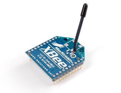
XBee Arduino Interfacing


Hello friends! We have already covered the Introduction to XBee Module and Interfacing of XBee with Computer. In this tutorial, we will connect our configured radios to two Arduino UNO Rev3 boards and use a pushbutton on one board to control the built-in LED on the other.
We will build the project in stages. First, we will establish the power and serial connections. Next, we will define the messages sent between the boards. Finally, we will write separate sender and receiver sketches and examine how they handle button bounce, incomplete messages, and a lost wireless connection.
The example assumes two compatible radios already configured for transparent serial communication at 9600 baud. The address values carried forward from the previous lesson apply to classic S1 802.15.4 firmware. Radios using another supported protocol can carry the same application messages after you configure their network using the correct product instructions.
What the Project Will Do
Arduino A reads a pushbutton. When you hold the button down, it asks Arduino B to turn its built-in LED on. Releasing the button asks B to turn the LED off. The sender also repeats the current state once per second, allowing the receiver to recover when an individual message is missed.
Arduino B accepts only two complete commands: LED,1 and LED,0, each terminated by a newline. After applying a valid command, it sends an acknowledgement. If no valid command arrives for three seconds, it turns the LED off.
This is a state-control example. Repeating LED,1 leaves the output on; it does not toggle the output repeatedly. That distinction matters on a wireless link, where a message may be retried or repeated deliberately.
Components Required
| Component | Quantity | Notes |
|---|---|---|
| Arduino UNO Rev3 | 2 | The sketches use the classic AVR UNO pin arrangement |
| Compatible XBee radios | 2 | Configured and able to communicate before installation |
| XBee breakouts or shields | 2 | Check their regulation and logic-translation features |
| Suitable regulated radio supplies | 1 per endpoint | Required unless provided by the chosen interface board |
| UART-compatible logic translation | As required at both endpoints | Match 5 V controller signals to the radio's interface |
| Normally open pushbutton | 1 | Connect between sender D4 and ground |
| USB cables, breadboards, and jumper wires | As required | For programming, power, and local connections |
The receiver uses its onboard LED, so an external LED and resistor are not required for the first exercise. Keep the first circuit small. Extra sensors and actuators make it harder to identify whether an early fault belongs to the radio link or the application.
Power and Logic Levels Come First
The classic UNO Rev3 operates with 5 V logic. A bare legacy XBee S1 uses a lower-voltage supply and UART interface. Regulating the radio's power does not automatically translate the signal coming from an Arduino output.
Use an interface board designed for your exact combination, or provide a suitable radio regulator and logic translation. For each signal direction, compare the source's guaranteed output levels with the destination's input thresholds and maximum ratings. A reliable interface needs compatible limits, not merely a nominal voltage that looks close.
Arduino lists a 50 mA limit for the UNO Rev3's 3.3 V output. That is little margin for a standard legacy S1, and insufficient for higher-current S1 PRO transmission. Consult the UNO Rev3 specifications and the matching Digi module specifications when selecting the supply.
Example Power Budget
Suppose the chosen radio requires up to 60 mA for the operating conditions you intend to support, and the breakout circuitry adds another 5 mA. Using an illustrative 30% current margin gives:
Idesign = (60 + 5) × 1.30 = 84.5 mA
Those assumed values describe the calculation method, not every XBee. Select the actual parts using the relevant maximum and transient requirements. A regulator must also remain stable with its required capacitors and dissipate the heat produced by its input-to-output voltage drop.
At each endpoint, connect the Arduino, level translator, radio, and local power supply to a common ground. There is no requirement for a ground wire between the two remote endpoints; the radio carries data across that separation.
Wiring the XBee to Arduino UNO
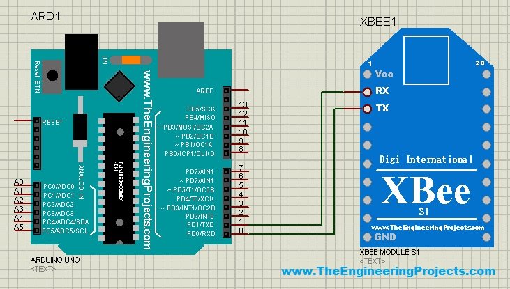
The original tutorial connected the radio to the UNO's main serial pins. We will use a separate software serial interface on D2 and D3 so that the USB Serial Monitor remains available for messages and diagnostics. The original illustration is retained for context below; use the updated connection table for the sketches in this lesson.
| Connection | Destination | Interface requirement |
|---|---|---|
| Arduino D3, software TX | XBee DIN, pin 3 on classic S1 | Translate the UNO's 5 V output to the radio's input level |
| XBee DOUT, pin 2 on classic S1 | Arduino D2, software RX | Use translation where required to meet guaranteed input thresholds |
| Regulated radio supply | XBee VCC, pin 1 on classic S1 | Use the voltage and current rating for the selected module |
| Local common ground | XBee GND, pin 10 on classic S1 | Join to Arduino and translator ground |
Connect the sender's pushbutton between D4 and ground. The sketch enables the internal pull-up, so an unpressed button reads HIGH and a pressed button reads LOW. A four-terminal tactile switch usually contains two internally connected pairs; identify the pairs so pressing it actually changes the connection.
Leave UNO pins D0 and D1 free for this version. If your shield routes the radio permanently to D0/D1, use its jumpers to select the intended pins or adapt the program and upload procedure deliberately. Changing a wire without changing the corresponding serial object in the sketch will not move the serial interface.
Confirm the Radio Configuration
Configure the radios using the computer lesson before installing them on the Arduino boards. For its S1 exercise, A uses MY=1111 and DL=2222; B uses MY=2222 and DL=1111, with DH=0. Both use the same channel and PAN identifier.
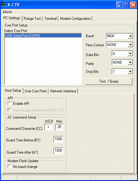
The preserved XCTU image belongs to the original configuration walkthrough. The application sketches below expect transparent mode, an awake radio, and a 9600-baud local UART. They do not enter AT command mode during normal operation.
That separation is useful: XCTU handles initial radio configuration, while the Arduino handles the button and LED messages. Repeatedly sending +++ inside the control loop can interrupt payload transmission and introduces guard-time requirements that this application does not need.
Define the Messages Before Writing Code
| Message | Direction | Meaning |
|---|---|---|
LED,1\n | A to B | Set the LED on |
LED,0\n | A to B | Set the LED off |
ACK,1\n | B to A | A valid on command was applied |
ACK,0\n | B to A | A valid off command was applied |
Here \n represents one newline byte, not a backslash followed by the letter n. In the Arduino string literals, the compiler converts that escape sequence into the correct byte.
The receiver may obtain a message in several pieces, so it collects bytes until the newline. It uses a bounded buffer and discards an overlong line. This prevents an incomplete or unexpectedly long input from writing beyond the available storage.
Sender Code: Read the Button and Transmit Its State
Create a new sketch for Arduino A. In SoftwareSerial xbee(2, 3), the receive pin comes first and the transmit pin comes second. This ordering is defined in Arduino's SoftwareSerial interface.
#include <SoftwareSerial.h>

SoftwareSerial xbee(2, 3); // Arduino RX, Arduino TX

const byte BUTTON_PIN = 4;
const unsigned long DEBOUNCE_MS = 30;
const unsigned long REPORT_MS = 1000;

int lastReading = HIGH;
int stableState = HIGH;
unsigned long lastChange = 0;
unsigned long lastReport = 0;

void sendState() {
  if (stableState == LOW) {
    xbee.print("LED,1\n");
    Serial.println(F("Sent: LED,1"));
  } else {
    xbee.print("LED,0\n");
    Serial.println(F("Sent: LED,0"));
  }
  lastReport = millis();
}

void setup() {
  pinMode(BUTTON_PIN, INPUT_PULLUP);
  Serial.begin(9600);
  xbee.begin(9600);
  lastReading = digitalRead(BUTTON_PIN);
  lastChange = millis();
  sendState();
}

void loop() {
  unsigned long now = millis();
  int reading = digitalRead(BUTTON_PIN);

  if (reading != lastReading) {
    lastReading = reading;
    lastChange = now;
  }

  if (now - lastChange >= DEBOUNCE_MS &&
      reading != stableState) {
    stableState = reading;
    sendState();
  }

  if (millis() - lastReport >= REPORT_MS) {
    sendState();
  }

  while (xbee.available() > 0) {
    Serial.write(xbee.read());
  }
}
How the Sender Handles Button Bounce
A mechanical contact can open and close several times during one physical press. The program records the most recent raw transition and accepts a new stable state only after the input remains unchanged for 30 ms.
The debounce interval is a starting value for this example. Different switches and wiring conditions can require adjustment. Arduino's official debounce example explains the same underlying timing problem.
The sender reports immediately after accepting a state change and repeats the state every second. It does not use a long delay() to wait for the next report, so it can continue reading the button and collecting acknowledgement bytes.
Elapsed time is calculated by subtracting unsigned timestamps. On the classic AVR core, millis() uses an unsigned long counter; this subtraction pattern handles its rollover for these short intervals. The implementation is available in Arduino's timer source.
Receiver Code: Parse Commands and Control the LED
Create a separate sketch for Arduino B. The radio wiring is identical, but this board does not need the pushbutton. Its built-in LED starts off, and only an exact valid command changes its state.
#include <SoftwareSerial.h>
#include <string.h>

SoftwareSerial xbee(2, 3); // Arduino RX, Arduino TX

const unsigned long LINK_TIMEOUT_MS = 3000;
char line[16];
byte used = 0;
bool droppingLine = false;
bool linkActive = false;
unsigned long lastCommand = 0;

void applyCommand() {
  bool ledOn;

  if (strcmp(line, "LED,1") == 0) {
    ledOn = true;
  } else if (strcmp(line, "LED,0") == 0) {
    ledOn = false;
  } else {
    Serial.println(F("Ignored unknown command"));
    return;
  }

  digitalWrite(LED_BUILTIN, ledOn ? HIGH : LOW);
  lastCommand = millis();
  linkActive = true;

  if (ledOn) {
    xbee.print("ACK,1\n");
    Serial.println(F("LED on"));
  } else {
    xbee.print("ACK,0\n");
    Serial.println(F("LED off"));
  }
}

void setup() {
  pinMode(LED_BUILTIN, OUTPUT);
  digitalWrite(LED_BUILTIN, LOW);
  Serial.begin(9600);
  xbee.begin(9600);
  Serial.println(F("Receiver ready"));
}

void loop() {
  while (xbee.available() > 0) {
    char c = (char)xbee.read();

    if (c == '\n') {
      if (!droppingLine && used > 0) {
        line[used] = '\0';
        applyCommand();
      }
      used = 0;
      droppingLine = false;
    } else if (c == '\r') {
      // Accept terminals that add carriage return before newline.
    } else if (!droppingLine) {
      if (c < 32 || c > 126) {
        droppingLine = true;
      } else if (used < sizeof(line) - 1) {
        line[used++] = c;
      } else {
        droppingLine = true;
        Serial.println(F("Ignored overlong command"));
      }
    }
  }

  if (linkActive &&
      millis() - lastCommand >= LINK_TIMEOUT_MS) {
    digitalWrite(LED_BUILTIN, LOW);
    linkActive = false;
    used = 0;
    droppingLine = false;
    Serial.println(F("No valid command for 3 s; LED off"));
  }
}
Why the Receiver Waits for a Complete Line
A call to available() tells us that bytes are waiting; it does not promise that an entire command has arrived. The receiver therefore maintains its buffer between iterations of loop(). The newline is the application-level boundary.
The 16-byte array reserves one byte for the terminating null character used by strcmp(). An overlong line is discarded until its newline arrives, preventing a suffix of the bad line from being mistaken for a new command.
Only a recognized command refreshes the communication timer. Random characters cannot keep the LED on indefinitely. Once a valid message returns, the receiver accepts the requested state again.
What the Acknowledgement Means
The receiver sends its acknowledgement after processing the command. The sender displays those reply bytes on the USB Serial Monitor. This is more informative than printing only the outgoing request.
The demonstration does not match acknowledgements to numbered transactions or implement a retry queue. Instead, it periodically reports the desired state. For operations where repeated execution matters, introduce sequence numbers and a clearly defined acknowledgement policy before extending the protocol.
Upload the Sketches and Run the Exercise
- Disconnect power while assembling each radio interface, then inspect the connections against the table.
- Connect Arduino A by USB, select its board and port, and upload the sender sketch.
- Connect Arduino B, select its port, and upload the receiver sketch.
- Open a 9600-baud Serial Monitor for each board using separate IDE windows or suitable terminals.
- Power the radios with their configured settings and keep their antennas separated on the bench.
- Press and hold A's button, then release it while observing B's LED and both serial displays.
The expected behavior is that the LED follows the debounced button state. You should see a sent-state message on A and an applied-state message on B, followed by an acknowledgement at A. Periodic reports continue even when the button is untouched.
With the LED on, remove power from the sender radio. B should turn its LED off after approximately three seconds without a valid command. Restoring the link allows the next periodic report to restore the requested state. This is an expected-behavior exercise; the timing on your hardware includes communication and processing delays.
Opening a Serial Monitor can reset an UNO through its USB interface. A startup message or a brief off state following that action is therefore different from an unexplained radio failure. Observe the startup behavior deliberately so that it does not confuse later diagnosis.
Calculate the Message Load and Response Time
The message LED,1\n contains six bytes: three letters, a comma, a digit, and a newline. With 8N1 UART framing, it occupies:
tUART = 6 × 10 / 9600 = 0.00625 s = 6.25 ms
The acknowledgement also contains six bytes. One state report and one acknowledgement each second therefore carry twelve application bytes per second across the two directions. That is a very small load for the local 9600-baud interfaces, although it excludes RF and any lower-layer overhead.
Button response includes several contributions: the debounce interval, sender UART serialization, radio packetization and transfer, receiver UART output, and receiver processing. Do not interpret the 6.25 ms calculation as the total time between pressing the button and seeing the LED.
For a 30 ms debounce interval, the intentionally added input filtering is already larger than one six-byte UART serialization time. Increasing the baud rate would therefore have limited benefit if the visible delay mainly came from debounce or radio configuration. Measure the complete system before optimizing one part.
Understanding SoftwareSerial's Limits
SoftwareSerial is convenient here because it leaves the UNO's USB serial channel available and our messages are short and infrequent. It relies on processor timing and interrupts, so it is a poor substitute for an additional hardware UART in a demanding communication design.
Keep this example to one software serial receiver. If you add another serial sensor, lengthy interrupt handlers, or sustained traffic, reassess the architecture. Boards with additional hardware UARTs can provide separate radio and debug channels without the same software-timing constraints.
Radio receive buffers and Arduino serial buffers are finite. A program that spends long periods performing other work can lose incoming data even when the wireless link is excellent. Short messages, bounded processing, and suitable flow control are part of the communication design.
Troubleshooting the Arduino Connection
| Observation | Possible cause | What to inspect |
|---|---|---|
| No sender messages on USB | Wrong sketch, port, or Serial Monitor speed | Select the sender board and 9600 baud |
| Sender always reports the button pressed | D4 held low | Check switch terminals and ground wiring |
| A reports commands but B receives nothing | UART wiring, radio configuration, power, or mode | Check D3 to DIN and DOUT to D2 at both ends |
| B changes the LED but A sees no reply | Return address or reverse UART path | Check B's destination and A's receive connection |
| B ignores typed commands | Wrong case or missing newline | Send exactly LED,1 or LED,0 followed by newline |
| LED goes off periodically while the button is held | Valid reports stop reaching B | Inspect supply interruptions, packet loss, and blocked serial handling |
| Upload fails with a shield installed | Shield shares the upload UART | Check its D0/D1 routing and programming jumpers |
If the application fails, return the radios to the computer adapters and repeat the known terminal exchange. That separates radio configuration from Arduino wiring and code. Reintroduce one Arduino endpoint at a time when locating the fault.
Practical Review and Next Improvements
This project retains the original tutorial's purpose: use an Arduino input to send a wireless instruction that another controller can act on. The separate sketches make the sender and receiver responsibilities explicit, and the text messages make the traffic readable during development.
The receiver's timeout is a simple response appropriate to this LED demonstration. It is not a complete safety design for a motor, heater, or mains appliance. Any extension needs an output stage suited to its load and behavior chosen for the consequences of communication failure.
Useful next steps include adding sequence numbers, recording acknowledgement time, including an application checksum, or moving to XBee API mode when source addresses and transmit status are required. Add one feature at a time so you can explain how it changes the protocol.
For related material, see Home Automation Project using XBee and Arduino and the XBee Library for Proteus. A simulation can help examine supported program behavior, while real hardware is needed to establish supply stability, timing, and radio performance.
Frequently Asked Questions
Do I need an XBee library in the Arduino sketch?
For this transparent serial example, no dedicated XBee API library is required. The sketches send and receive ordinary serial payload. SoftwareSerial supplies the additional UART-like connection on the classic UNO.
Why are D2 and D3 used instead of D0 and D1?
This leaves the UNO's primary serial connection available for USB uploading and diagnostics. D2 is the software receive input, and D3 is the software transmit output in both sketches.
Can I upload the same sketch to both boards?
Not for this exercise. One sketch reads the button and sends state requests; the other parses those requests and controls its LED. Upload the appropriate role to each board.
Why repeat the command when the button has not changed?
A missed transition should not leave the receiver permanently in the wrong state. Periodically reporting the desired state allows recovery and provides the valid-message activity used by the receiver's timeout.
Can this code operate a relay?
The message-processing idea can be extended, but a relay requires an appropriate driver and power arrangement. Choose a communication-loss state for the actual load and develop the additional protection and authorization that application needs.
Will this exact pin arrangement work on every Arduino?
No. SoftwareSerial support, receive-capable pins, UART names, and logic voltages depend on the board and core. For another board, check its documentation and adapt the serial interface and electrical connections together.

I am bit confused about Tx of xbee should be connected to Tx or Rx of arduino and similarly, Rx of xbee as well. Plz do help me as soon as possible
Thanks in advance.
1 reply
Hi bro,
don't get confused .... if you are using Arduino UNO then simply connect pin # 2 of UNO Board with pin # 2 of XBee .... and pin # 3 of UNO Board with pin # 3 of XBee and you are on go ...
aoa.
ZAIN bhai.....i want to puchase xbee S1 module...if it is availbel on your garage kindly inform us asap.
we need it urgently..send me your cntact nbr.(0302-7437038).
I wish to interface xbee and pic18f4520 so that heart beat readings from a heart sensor can be gotten on a pc wirelessly.how do i program the pic to send values to xbee
1 reply
Hi,
XBee works at TX / RX so use the same way as described above but as you are using PIC instead of Arduino so in order to send the reading you have to use serial pins of PIC microcontroller , If you want we can also provide you the complete coding, send us a message on Skype or help@theengineeringprojects.com.
Thanks.
i am working on arduino mega-2560 to interface the vibration and distance sensor.i used a router AT and coordinator AT for Tx and Rx respectively. i have picked the sensor values but i am failed to transmit this data via xbee to another remote xbee( i am using a series 2 xbee). i tried many a times but can't recieve the data on Rx side. i need your help. can you provide me the Rx and Tx code for this.
i want to make a temperature monitoring sysytem using zigbee and pic 16f877a can u please tell me the interfacing for the same .
1 reply
The logic will be exactly the same, zigbee works on Serial protocol so you simply need to connect the TX/RX pins of XBee to RX/TX pins of PIC respectively and you will be able to send or receive the data.
Salam sir,
We are planning to use Xbee for our final year project which is to design an automated guided vehicle based on wireless communication to accurately pick and place objects on respective loading and unloading stations.The issue is I just read your tutorial and Now I am confused , because we wanted one Xbee (transmitter) to be conncetd with PC/laptop and by using that Xbee we could communicate with Xbee (receiver) interfaced with arduino ,The information that we wanted to communicate is the location of object placed at shelves at loading station.But according to what you wrote we might be needing two ARDUINO UNO boards .Kindly let me know is it possible to interface one xbee(tranmitter) with pc/laptop and xbee(receiver) with arduino and they will communicate??
1 reply
Wsalam,
Yeah you can communicate between two xbees without using arduino, as in your case one xbee is connected with arduino and the other one directly to computer , it will work fine. Moreover you need to use usb explorer on pc side.
Thanks.
Thank-you very much sir for your kind reply , Would you please enlighten me a little bit on what is Xbee explorer and and what is Xbee regulated?? Moreover we want to buy XBee module.Your guidance is required as to what components are necessary .
1 reply
You can xbee from us and xbee explorer is a usb module in which you plug xbee and then connect it to your computer via usb. For components details you can call me and will let you know the details. Check the contact us page.
Thanks.
Hi, i'm using xbee series 2 and arduino uno board for both transmitter and receiver.
I configured both of the xbees to AT mode. I've connected pin 2 to transmitter and pin 3 to receiver for both.
However, i still could not received data from one to another.
Hello sir,
Can u please provide me with the code for interfacing Xbee with atmel8 microcontroller
Hello Sir
can you provide for us a rf module library. and i would like to know if i can create a remote control using the xbee interface with arduino nano how should i connect them. i want one xbee connect to the arduino and the other without the arduino is it possible? please help Sir urgent
1 reply
Kindly add me on Skype and we will discuss it out. My Skype id is theenggprojects. Moreover, XBee Library for Proteus is given on the blog. Make a search.
Thanks.
. Sir i have done my Fyp by using Aurdino with Xbee . Now I want to use 8051 instead of Aurdino. But i am confused by reading your artcules. Sir it is right that Vcc pin of Xbee should be connect with 3.3v supply But plz sir tell me that why i can not connect Rx or Tx pin of 8051 directly to XBee .As i have checked the Tx pin of Aurdino Uno by multimeter it was 5v and i have directly connected to the Rx pin of Xbee and works properly.
Hello sir!
Do we really need Xbee shield to interface with any micro-controller ?
Is Xbee S1 and S2 model are serial compatible with for all microcontrollers having 5V operating vltg.??
Please tell me If you knw what I mean!! Thank you!
Shriniwas K.
Hello sir,
Can u please provide me with the c code for interfacing Xbee with atmel16 microcontroller
xbee interfacing with Atmega16 c code
if I have several Xbees connected to sensors or appliances.
and I need to control them through a control unit that comprises an arduino and Xbee as a coordinator ….I just have no clue how to write the code???…I used to specify the pin number in case I was connecting, for instance, a LED to the arduino….I don’t know what I have to do now
i want you to help me with simple serial receiving code thats needed on the second arduino.
I am working on the Xbee Arduino communication in Proteus.
i need some help in that, as im not able to connect xbee to arduino.
i connect Tx od xbee with tx of arduino but whenever i run simulation xbee node get disappear.
Comments
23