


Simple Arduino Calculator


We all use calculators in our daily life, whether you are working in an office or counting money at the bank, you are buying your daily grocery or doing shopping online, you will find calculators in different forms everywhere. In fact, the computer was initially considered a giant calculator. So if it is that common, why do we not make our own calculator?
Before going into the details of the project, it is good to know some history of that, let’s know some facts about the calculator. So the first known device for calculation is Abacus. And the first digital calculator was made by Texas Instruments in 1967 before that all calculators were mostly mechanical and they did not need any electronic circuits. The first all-transistor calculator was made by IBM and it is claimed that the calculator performed all the four basic operations such as addition, subtraction, multiplication, and division.
Software to Install :
In this, we will be going to use the Proteus simulation tool and we will make our whole project using this software only. But no need to worry while using the actual components because if our project works perfectly with simulation, it will definitely work with actual hardware implementation. And the best part of the simulation is, here we will not damage any components by making any inappropriate connections.
If you don’t have an idea about Proteus, Proteus is a software for the simulation of electronic circuits and here we can use different types of microcontrollers and run our applications on them.
So for this project, we need to install this software. This software has a big database for all electronics components but still, it lacks some, therefore we have to install some libraries for modules which we are going to use in this project.
- First, install the Proteus Library for Arduino UNO.
- Next, install the Proteus library for LCD module.
Project overview :
In this project, we will take input from the user using a keypad and perform the operation using Arduino UNO and display the result on an LCD display.
- Arduino UNO - It is used for performing calculation-related operations, other user-related operations like interfacing with keypad module and LCD module.
- 16x4 LCD module- It is used to display user-related messages such as input digits and selected arithmetical operations and calculated results.
- 4x4 Keypad- It is used for user input. From this module, the user can enter the numerical values and arithmetic operations.
Our project will work the same as a normal digital calculator such that the user will enter two numerical values and select arithmetic operations which she/he wants to perform on the given values. Once the user clicks on the equal button, thereafter Arduino UNO will calculate the output and display the result on the LCD module.
Components required :
- Arduino UNO
- 16x2 LCD module
- 4x4 Keypad module
Components details:
-
Arduino UNO
- Arduino UNO is an open-source development board that we have used in this project.
- It works on the ATMega328P microcontroller developed by Atmel.
- It has an 8-bit RISC based processing core and up to 32 KB of flash memory
- It has 14 digital input/output pins from D0 - D13 with a resolution of 8 bits, these pins can be used for taking any digital input or can be used as output pins for controlling peripherals.
- In the 14 digital pins, there are 6 PWM pins.
- It is suggested that you do not use the D0 and D1 pins of Arduino UNO for digital read or write purposes because they have an extra functionality of UART communication.
- Arduino UNO has 6 analog input/output pins from A0-A5, which can be used to read analog values.
- Analog pins have 10 bits of ADC (Analog to Digital convertor) resolution ranging values from 0 - 1023.
- Arduino UNO has one hardware UART peripheral (D0, D1), one I2C peripheral, and one SPI peripheral.
- We can use the power supply from 7 to 12 volts to power the Arduino UNO, but it is suggested to use a voltage supply of less than or equal to 9 volts but not below 5 volts.
- We will use the Arduino IDE for writing and uploading the code on Arduino UNO. It is an open-source software developed by Arduino.
-
LCD Module
- LCD stands for Liquid Crystal Display, and this display is made using liquid crystal technology.
- For more knowledge of how LCD works, prefer this link Working of LCD display.
- In this project, we have a 16x2 LCD display which means we can display a max of 32 ASCII characters on this at a time.
- The LCD module has 16 pins but we will not use all the pins in this project.
- The LCD module can be used in two different modes, the first is 4-bit mode and the second is 8-bit mode.
- We will use the 4-bit mode in this project, therefore, we have to connect only 4 data pins of the LCD module.
- The major difference between 8-bit mode and 4-bit mode is, an ASCII character is 8 bit long so when we use 8-bit mode, LCD will process the data in single instruction but in 4- bit mode, microcontroller will send 2 chunks of 4 bits and the LCD will process that in two instructions.
- To read more about the difference between 8-bit mode and 4-bit mode refer to this link Different modes of the LCD module
- There are two registers in the LCD module: The Data register and the Command register.
- When the RS(Register Select) pin is set to logic high, the data register mode is selected, and when it is set to logic low, the command register mode is selected.
- The RS pin will be set to logic high to display the data on the LCD.
- The operating power supply will be 5 volts for the LCD module.
-
4x4 Keypad
- It is a membrane-based push keypad.
- We have used a 4x4 keyboard which means it has 4 rows and 4 columns.
- It has 0-9 numbers and basic arithmetic operations like addition, subtraction, multiplication, and division.
- It has four pins for each row and 4 pins for each column.
- The switch between a column and a row trace is closed, when a button is pressed, which completes the circuit and allows current to pass between a column pin and a row pin.

Circuit diagram and working:
Now, let’s start designing our circuit diagram for the calculator.
- Make sure we have the correct and updated version of the Proteus software.
- And make sure we have all the required libraries for the modules which we will be using in this project.
- Now click on the new project (Ctrl+N) to start a new project of the Arduino calculator.
- Import all the required components in the workspace.

Now we have all the required components in the workplace as follows.

Let's start connecting them.
- First, we will connect the LCD module with the Arduino UNO module.
- As we are using the LCD module in the 4-bit mode, therefore, we will have 4 pins for data, 1 pin for enable pin, and 1 pin for register status pin.
- For data pins, connect the D4, D5, D6, and D7 pins of the LCD module to the D2, D3, D4, and D5 pins of Arduino UNO respectively. And connect the RS pin with D0 and Enable with D1 pin.
- To use the LCD module in write mode, the R/W pin must be connected to the ground.
- Now connect the keypad with the Arduino UNO board. As it is a 4x4 keypad, it will use 8 pins of the Arduino UNO board.
- For row lines, we will use D13, D12, D11, and D10 pins and for column lines, we will use D9, D8, D7, D6 pins respectively.

That is all for connection. Make sure all the connections are correct, especially for keypad’s row and column connections otherwise we will get the wrong values from the keypad input.
And while working on the actual components, power the backlight of the LCD module and set the appropriate contrast, else nothing will be visible even if that has been displayed.
Arduino code for calculator:
Downloading and including libraries
- Before going to write application code, we need libraries for the 16x2 LCD module and 4x4 keypad module.
- We can download the library for the LCD module using this link LCD module library.
- And use this link Keypad module library for keypad module.
- Most of the Arduino related libraries are available on the Arduino official website.
- We can add libraries in the Arduino using zip file or the manage libraries option.
- If you have downloaded the libraries from the link then we have to click the option of “Add Zip Library” otherwise click on the manage libraries option and search for the required library.

- After adding all the required libraries, include them in our application code.

Code declaration
- We will declare the pins in the code as per we have connected them in the circuit diagram.
- So first create the object for the LCD module and enter the pins we have used for LCD module connections.
- While entering the pins in the LCD module object parameters, maintain the sequence as follows:

In the above-mentioned image, the first argument for RS pin, second for Enable pin, and rest four for data pins.
- Now declare the variables for the Keypad module. We will use a 2D char array for storing keypad values, 2 arrays for storing pins used for rows and columns. And declare a ‘mykeypad’ name object for keypad class.

- After that, declare some general variables which we will use to store the values like user input, output of calculation and operation.

- After declaring and initialising all the variables and objects, we will start writing in the “void setup()” function.
Void setup function
- This is one of the most important functions of Arduino programming.
- As per the structure of Arduino programming, we can not remove this function from our code.
- It will execute only once when the controller starts the execution.
- Here, we will declare the modes of pins which we are going to use and setup functions related to the LCD module.
- Display the welcome message on boot up of our calculator.

- Here, we will begin the LCD module and set the cursor at 0,0 position and print the welcome message “The Engineering Projects Presents Arduino Calculator”.
- As this message is written in the setup function, it will run every time once when the controller reboots and after 5 second delay, the LCD display will be cleared.
Void loop function
- This is the second most important function of Arduino coding.
- As per the structure of Arduino code, it must be in the code otherwise it will raise errors.
- We will write our main application code here which we want to run in a continuous loop.
- First, we will get the pressed key from the user, using the “myKeypad.getKey()” function and store that value in the variable named ‘key’.

- And if the ‘key’ variable is one of the numbers, we will store that in the first number variable “num1”. And display that on the LCD display.

- Now there can be two conditions, first if the user wants to perform the operation on a single digit number, in that case enter the operation which the user wants to perform. Then ‘key’ will be equal to ‘+’, ‘-’, ‘/’, ‘*’.

And required operation will be stored in the ‘op’ variable and a flag will be set for taking the second number.
- Now the loop runs and control reaches to where ‘key’ is equal to number but this time it will go in the else condition of ‘presentValue’ variable because this variable is set ‘true’ from the operation condition.

- And in this condition, the value will be stored in the ’num2’ variable. And here we will set the flag ‘final’.
- Now the user will click the equal button to get the result. And the control reaches that condition and performs the operation on the values entered by the user and the same is stored in the ‘op’ variable.
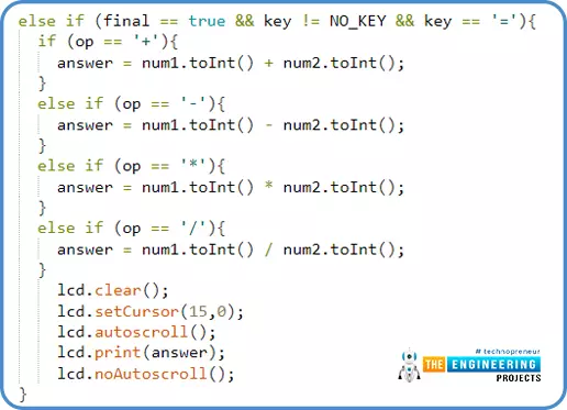
- Hence, the answer will be displayed on the LCD display.
- After that, to clear the display, click the ‘C’ button. It will clear the LCD display and reset all the variables to their initial value.

- Above mentioned condition is the first condition but in the second condition, when the user will enter more than one digits, then we shift the LCD cursor as per the length of the number entered.
- To handle that situation, we will get the length of the entered digits and shift the LCD display cursor accordingly.

That is all the code, we need to run an Arduino Calculator.
Results/Working
Now, we have completed the coding and circuit part, it is time to run the simulation in the Proteus.
- The first step to start the simulation, to add the hex file of our application code in the Proteus simulation.
- To add the hex file, click on the Arduino UNO module and a new window will pop up then click on the Program Files option. Afterwards, browse to the folder of application code.

- Now it is ready to start the simulation, click on the ‘Play’ button.
- When simulation starts, the LCD display will show the welcome message.

- Let’s suppose, we want to add two numbers 7 and 5. So click the same on the keypad.
- After entering the values, click on the “=” button, it will display the result.

- This is the same way we can operate different calculations using this calculator.

- After that, click on this button which will clear the LCD display.
I hope we have covered everything related to Arduino calculator i.e. Simulation, Code, Working etc. but still if you find anything confusing, ask in the comments.
Thanks for reading this project out. All the best for your projects!


