line following robot, line following robotic waiter, line following robot arduino, arduino line following code, line following robotic waiter
TEP , The Engineering Projects , Boxes

Line Following Robotic Waiter using Arduino

Shares 2.5K Views
Reaction 40
Reaction 700
Reaction 60
Reaction 25
Reaction 60
Shares: 691
TEP , The Engineering Projects , PCBWAY

line following robot, line following robotic waiter, line following robot arduino, arduino line following code, line following robotic waiter
Hello friends, I hope you all are fine and having fun with your lives. Today, I am going to share a new project which is Line Following Robotic Waiter. I hope you guys are gonna enjoy it. I have shared all the details below so that if you wanna design it then you can easily do it. I have designed this project for a client and it worked quite perfectly so I thought to share it with you guys as well.

I have designed this Line Following Robotic Waiter using Arduino UNO board. I have also shared the code below and have given all the instructions but still if you got into any problem then ask in comments and I will solve your problems. I have also shared a video below which will show you the working of Line Following robotic Waiter. So, let's get started with it:

Line Following Robotic Waiter

First of all, let's have an overview of this Line Following Robotic Waiter:

Overview
  • In this project, I have designed an arena which has four tables on it as shown in below figure:
line following robot, line following robotic waiter, line following robot arduino, arduino line following code, line following robotic waiter
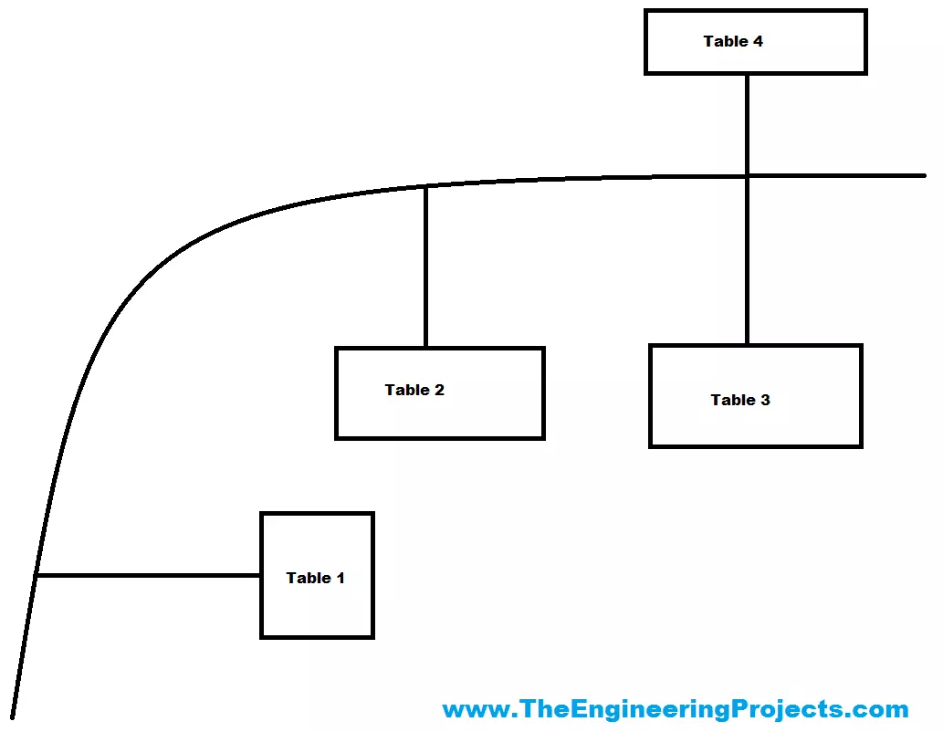
  • The robot will start from the Table 1 side and whenever someone call it from any table then it will reach that table and take the order.
  • After taking the order it will move back and will reach to the starting point again and wait for the next table call.
  • Now let's have a look at the components required to design thi Line Following Robotic Waiter:
Components
  • Let's have a look at the components list, which is required for designing this Robot. Here it is:
  • Arduino UNO
  • DC Motors
  • RF Module
  • 2 Relay Board
  • IR Sensors
  • These are the components required in order to design this Line following robotic waiter.
Mechanical Design
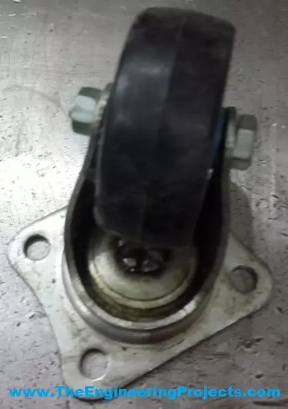
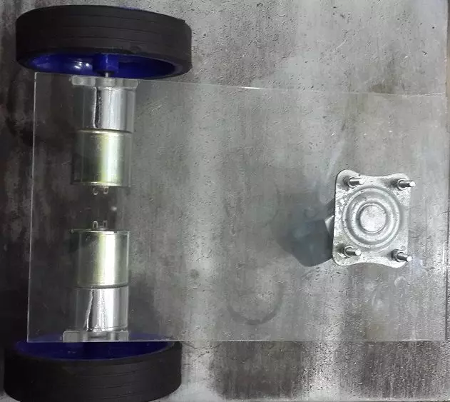
  • I have designed a three wheeler robot in which there were two wheels at the front side with DC motors while a free caster wheel at the back side.
  • I have used Acrylic Sheet as the body of the robot.
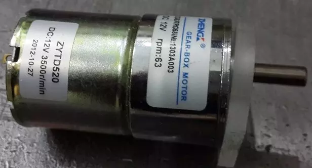
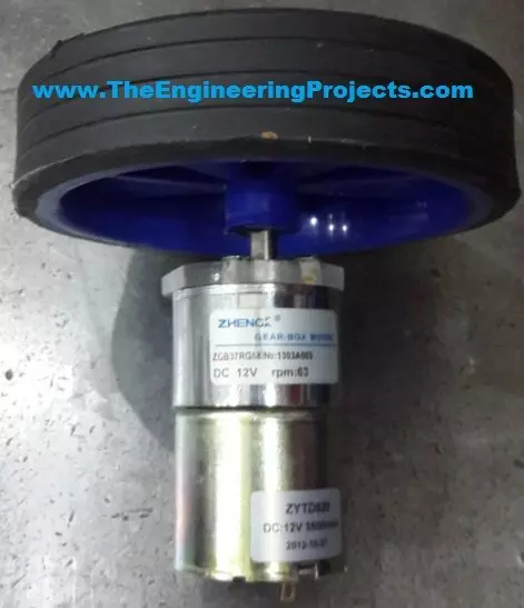
  • The DC Motor I have used for designing this project is shown in the below figure:
line following robot, line following robotic waiter, line following robot arduino, arduino line following code, line following robotic waiter
  • The caster wheel used is shown in below figure:
Line following Robotic Waiter 4
  • The coupled DC gear Motor with wheel is shown in below figure:
line following robot, line following robotic waiter, line following robot arduino, arduino line following code, line following robotic waiter
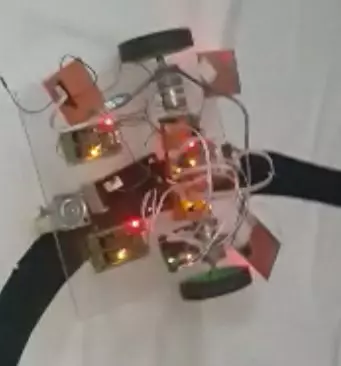
  • So I have designed two of such coupled motors and then combining all the above things together, we finally designed our Line Following Robotic Waiter as shown in below figure:
line following robot, line following robotic waiter, line following robot arduino, arduino line following code, line following robotic waiter
  • Now our mechanical Design is ready so let's design the electronic hardware:
Electronic Circuit Design
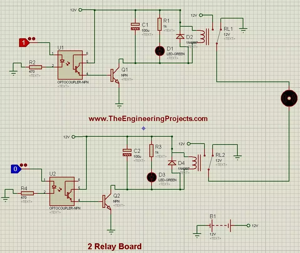
  • First of all, I have designed the DC Motor Driver which is also called 2 Relay Board.
  • This circuit diagram is shown in below figure:
line following robot, line following robotic waiter, line following robot arduino, arduino line following code, line following robotic waiter
  • Now in order to apply the signals to move the Motors I have used Arduino UNO board.
  • Moreover I have placed four IR sensors below this robot.
  • Two of these IR sensors are used for line tracking while the remaining two were placed on the sides for detecting the tables on both sides.
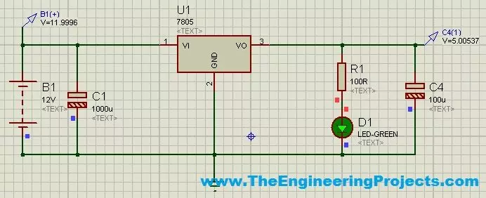
  • I have also designed a power supply to convert 12V into 5V.
  • The circuit diagram of power supply is as follows:
line following robot, line following robotic waiter, line following robot arduino, arduino line following code, line following robotic waiter
  • So, now let's have a look at the Arduino code required for Line Following Robotic Waiter:
Arduino Code
  • Here's the Arduino Code requried for Line Following Robotic Waiter.
#define motorL1 8
#define motorL2 9
#define motorR1 10
#define motorR2 11

#define PwmLeft 5
#define PwmRight 6

#define SensorR 2
#define SensorL 3
#define Sensor3 A0
#define Sensor4 A1

#define TableA A4
#define TableB A2
#define TableC A5
#define TableD A3

int OriginalSpeed = 200;
int TableCount = 0;
int TableCheck = 0;
int RFCheck = 10;

void setup() 
{
  Serial.begin (9600);
 
  pinMode(motorR1, OUTPUT);
  pinMode(motorR2, OUTPUT);
  pinMode(motorL1, OUTPUT);
  pinMode(motorL2, OUTPUT);
  
  pinMode(PwmLeft, OUTPUT);
  pinMode(PwmRight, OUTPUT);
  
  pinMode(SensorL, INPUT);
  pinMode(SensorR, INPUT);
  pinMode(Sensor3, INPUT);
  pinMode(Sensor4, INPUT);
  
  pinMode(TableA, INPUT);
  pinMode(TableB, INPUT);
  pinMode(TableC, INPUT);
  pinMode(TableD, INPUT);
  
  MotorsStop();
  
  analogWrite(PwmLeft, 0); 
  analogWrite(PwmRight, 0);
  delay(2000); 
 // Serial.println("fghfg");
  
}

void loop() {
  MotorsForward();
if((digitalRead(Sensor3) == LOW) && (TableCheck == 0)){TableCount++; TableCheck = 1;}
if((digitalRead(Sensor3) == HIGH) && (TableCheck == 1)){TableCheck = 2;}

if((digitalRead(Sensor3) == LOW) && (TableCheck == 2)){TableCount++; TableCheck = 3;}
if((digitalRead(Sensor3) == HIGH) && (TableCheck == 3)){TableCheck = 4;}
if((digitalRead(Sensor3) == LOW) && (TableCheck == 4)){TableCount++; TableCheck = 5;}
if((digitalRead(Sensor3) == HIGH) && (TableCheck == 5)){TableCheck = 0;}

if(digitalRead(TableA) == HIGH){RFCheck = 1;}
if(digitalRead(TableB) == HIGH){RFCheck = 2;}
if(digitalRead(TableC) == HIGH){RFCheck = 3;}
if(digitalRead(TableD) == HIGH){RFCheck = 4;}

if(RFCheck == TableCount){Table1();}
PIDController();
}

void MotorsBackward()
{
    digitalWrite(motorL1, HIGH);
    digitalWrite(motorL2, LOW);
    digitalWrite(motorR1, HIGH);
    digitalWrite(motorR2, LOW);
}

void MotorsForward()
{
    digitalWrite(motorL1, LOW);
    digitalWrite(motorL2, HIGH);
    digitalWrite(motorR1, LOW);
    digitalWrite(motorR2, HIGH);
}

void MotorsStop()
{
    digitalWrite(motorL1, HIGH);
    digitalWrite(motorL2, HIGH);
    digitalWrite(motorR1, HIGH);
    digitalWrite(motorR2, HIGH);
}

void MotorsLeft()
{
    analogWrite(PwmLeft, 0); 
  analogWrite(PwmRight, 0);
    digitalWrite(motorR1, HIGH);
    digitalWrite(motorR2, HIGH);
    digitalWrite(motorL1, LOW);
    digitalWrite(motorL2, HIGH);
}

void MotorsRight()
{
      analogWrite(PwmLeft, 0); 
  analogWrite(PwmRight, 0);
    digitalWrite(motorR1, LOW);
    digitalWrite(motorR2, HIGH);
    digitalWrite(motorL1, HIGH);
    digitalWrite(motorL2, HIGH);
}

void Motors180()
{
    analogWrite(PwmLeft, 0); 
    analogWrite(PwmRight, 0);
    digitalWrite(motorL1, HIGH);
    digitalWrite(motorL2, LOW);
    digitalWrite(motorR1, LOW);
    digitalWrite(motorR2, HIGH);
}

void PIDController()
{
  if(digitalRead(SensorL) == HIGH){analogWrite(PwmRight, 250);analogWrite(PwmLeft, 0);}
  if(digitalRead(SensorR) == HIGH){analogWrite(PwmLeft, 250);analogWrite(PwmRight,0);}
  if((digitalRead(SensorL) == LOW) && (digitalRead(SensorR) == LOW)){analogWrite(PwmRight, 0);analogWrite(PwmLeft, 0);}
}

void Table1()
{
   TableCount = 0;
   MotorsRight();
   delay(4000);
   while(digitalRead(SensorR) == HIGH);
   while(digitalRead(SensorL) == HIGH);
   while(1)
   {
       MotorsForward();
       PIDController();
       if(digitalRead(Sensor3) == LOW){break;}
   }
   MotorsStop();
   delay(1000);
   Motors180();
   delay(2000);
   while(digitalRead(Sensor3) == HIGH);
   while(digitalRead(Sensor3) == LOW);
   while(digitalRead(SensorL) == HIGH);
   //delay(500);
   while(1)
   {
   MotorsForward();
   PIDController();
   if(digitalRead(Sensor3) == LOW){break;}
   }
   //delay(1000);
   MotorsLeft();
   delay(4000);
   while(digitalRead(SensorL) == HIGH);
   while(digitalRead(SensorR) == LOW);
   while(1)
   {
       MotorsForward();
       PIDController();
       if(digitalRead(Sensor3) == LOW){break;}
   }
   MotorsStop();
   delay(1000);
}
  • This code will not work for you exactly.
  • The robot is following the line so I have placed some value for IR sensors so that my robot can follow.
  • When right IR sensor is HIGH then right motor moves a little faster and left motor slows down.
  • In this way I am making it to follow the line so you have to change such values in the code.
  • If you got into any issue regarding this project then add us on Skype and we will help you out.
  • Here's our final robot looks like:
line following robot, line following robotic waiter, line following robot arduino, arduino line following code, line following robotic waiter
  • Here's the video of Line following Robotic Waiter which will give you the better idea of how it worked:
That's all for today, I hope you have enjoyed today's project. Will meet you guys in the next tutorial. till then take care and have fun !!! :)
TEP , The Engineering Projects , Tags
Comments

Write a Comment

WordPress Google Twitter Facebook User
Robot
Comments Comments on ‘’ Line Following Robotic Waiter using Arduino ‘’ (22)
Comment
Reaction 40
Reaction 700
Reaction 60
Reaction 25
Reaction 60
sensor 4 never used in the code!!!....may I ask you to provide me with arduino config + the brief explanation for the code.. if that is possible to you sir... thanks in advanced yours naz
Comment
Reaction 40
Reaction 700
Reaction 60
Reaction 25
Reaction 60
Can you help and show me how to connect the ir kit and Audrino for this project. I am making this for my school project and having a problem in coding.
Comment
Reaction 40
Reaction 700
Reaction 60
Reaction 25
Reaction 60
hello sir, very impressive work can you help me to do such as this project using RFID Readers ??? Waiting your replay A.S.A.P
Comment
Reaction 40
Reaction 700
Reaction 60
Reaction 25
Reaction 60
We are living in modern era, we prefer automation over hand work. And we find everywhere, every time computerization work. No doubt it has made our lives easy and fast. In this article you have shared with us your excellent knowledge about robotic waiter. You have also shared a figure with us, which shows the table setting which the robot has to serve. I have a question how the robot will detect from which table it has to take orders? As you have shown four tables in figure, my question is that from which table it will start taking orders and how? Will it follow the preplanned path and take orders from only pre-decided tables as you have mentioned or it just takes random rounds and take orders randomly?
Comment
Reaction 40
Reaction 700
Reaction 60
Reaction 25
Reaction 60
Its just a great invention! I really appreciate your effort. Now it has become for us to minimize our mistakes by computerization. Here I have a confusion, will we put the robotic waiter at some fix point to take orders from customers or will there be any starting or ending points? Will robot take right or left turns too? Here’s another question, how robot will communicate with customers? What kind of signals customers have to give to call out robot for their orders? Kindly clear my points.
Comment
Reaction 40
Reaction 700
Reaction 60
Reaction 25
Reaction 60
Your article is really good! It explains all steps of robot construction very nicely. You have also uploaded figures which clears most of the doubts. But still some doubts are waiting for your response. Like, how it will be physically construct, which type of material will be good for robot’s body? As you have mentioned acrylic sheet for body construction, is it affordable sheet? If its possible for you then please share the diagram of body structure too. How many drive wheels it must have and also guide me at which points we have to fix them to receive or deliver orders smoothly? Also clear one thing more how the sensors will pass the instructions to drive wheels?
Comment
Reaction 40
Reaction 700
Reaction 60
Reaction 25
Reaction 60
Robotic waiter will be very useful for the success of any restaurant, it will put great impression on customers. To design a flawless robotic waiter which elements are essential and how to design it mechanically using those elements according to robot’s serving customers tasks?
Comment
Reaction 40
Reaction 700
Reaction 60
Reaction 25
Reaction 60
If we talk about circuit design of robotic waiter , I think it’s the most important step for the construction of a robot and according to me it’s the most time taking step. So for this step I need your help, kindly tell me for the application of signals which is considered the main function of robot, which type of Arduino should be purchased? Will your recommended Arduino works properly? Is it capable of serving tasks and handling the right sensors, left sensor for the movement of robot?
Comment
Reaction 40
Reaction 700
Reaction 60
Reaction 25
Reaction 60
Designing a line follow robotic waiter is very interesting job but its also a hectic job because we have to follow some principles. After Arduino procedure here’s you mentioned IR Sensors .How these sensors help robot to detect the tables? Are your mentioned sensors used for right and left directions only or for moving forward also? Does these sensors have some connection with Arduino and motor?
Comment
Reaction 40
Reaction 700
Reaction 60
Reaction 25
Reaction 60
Hi sir I really appreciate your effort of helping us and will be thankful too if you send me the link of IR sensors and DC motor you have used in this project?
Comment
Reaction 40
Reaction 700
Reaction 60
Reaction 25
Reaction 60
How we will make sure that robot moves on pre-defined line smoothly using sensors? What will be the strategy if we find robot turning too much to the right or the left side? How we will adjust it?
Comment
Reaction 40
Reaction 700
Reaction 60
Reaction 25
Reaction 60
Hey,You have done amazing job! Will you please help me to find out how can we stop line following robot at the desired point?
Comment
Reaction 40
Reaction 700
Reaction 60
Reaction 25
Reaction 60
Excellent work and knowledge you have shared with us. Just give me a favor, Which type of motor you have used in your project? Could you please also shared the link with me?
Comment
Reaction 40
Reaction 700
Reaction 60
Reaction 25
Reaction 60
I appreciate your services which you have done for engineering students. Could you please share an easy diagram of electronic circuit for better understanding?