- The JK flip-flop is named after his inventor known as Jack Kilby from Texas Instruments. The JK Flip-flop is also widely known as a programmable flip-flop as it can disguise other flip-flops based on the inputs applied.
Introduction to JK Flip Flop
JK Flip Flop is a universal flip-flop that makes the circuit toggle between two states and is widely used in shift registers, counters, PWM and computer applications. Before we nail down the details of JK Flip Flop, we must know what is Flip Flop.- Flip Flop comes with two stable states and is mainly used to store the state information of any circuit. The output of the flip-flop is directly related to the input applied. When you modify any of the applied input, it directly influences the output state of the device.
- We use language to collaborate with each other, similarly, electronic devices need some language pattern to collaborate with other electronic devices. They understand a language in terms of ones and zeros where former represents the HIGH state and later represent the LOW state of the circuit.
JK Flip Flop Symbol and Logic Table
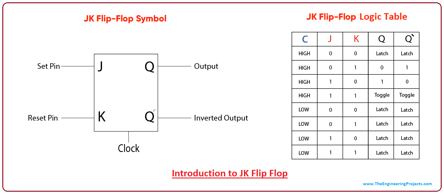
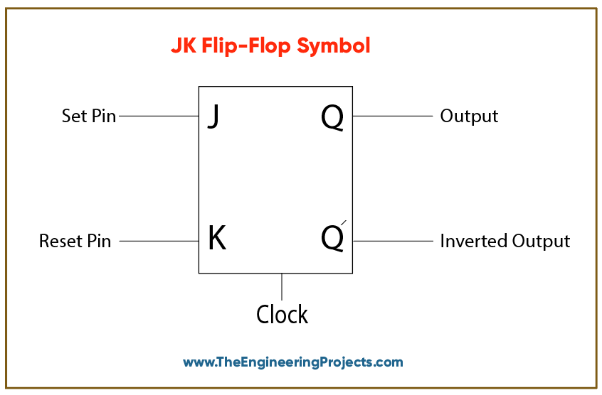
Following figure shows the symbol of Flip-Flop circuit.
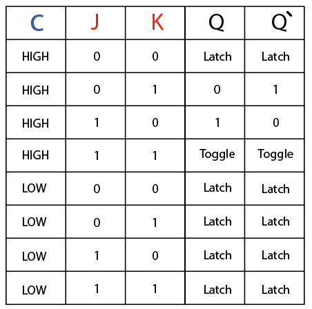
- The J and K are the inputs and Q is the output state of the flip-flop where Q' represents the inverted output state. In the presence of the clock signal, the output changes its state based on the applied inputs, producing a toggling function when both inputs are HIGH.

Difference between SR and JK Flip Flop
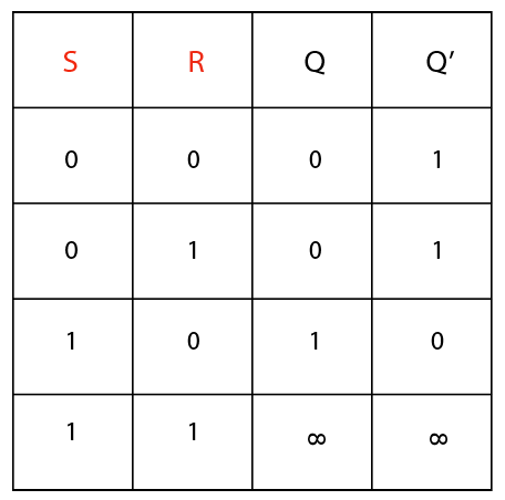
Two flip-flops are known as JK Flip and SR Flip are widely used in electronic applications. Using the SR flip-flop when both inputs are high, will generate an invalid condition. On the other hand, JK Flip Flop extensively removes the invalid condition, when both inputs are kept HIGH, by toggling the output alternatively between two states.- The JK Flip Flop is nothing but an improvised version of SR Flip Flop, where an undefined condition is avoided that may create a gross impact using the SR Flip Flop.

Difference between Flip Flop and Latch
The basic difference between a latch and a flip-flop is a clocking process. The latch is asynchronous where outputs are drastically influenced by the slight change in inputs.- A flip-flop is synchronous and edge-triggered that changes its state based on the control signal (clock signal) as it goes from HIGH to LOW and LOW to HIGH conditions.
- In other words, we can conclude, both latches and flip-flops are circuit element where the output depends on both: the current input and previous input. The flip-flop has a clock signal while the latch is deprived of it.
In an Active-high latch, the inputs are connected to ground, activating the latch by applying the HIGH signal on either of the inputs. If the SET input goes HIGH, it will keep the output HIGH even after the SET input goes LOW. The output will go LOW only when the RESET input turns HIGH.
And in an Active-low latch, the inputs are kept HIGH, activating the latch by applying the LOW signal on either input. When the SET input turns LOW, the output will go HIGH. The output remains in HIGH condition until the RESET pin goes LOW.
Applications
JK Flip Flops is widely used in electronic circuits with the main aim to store the state information of the device. Following are the major applications it can be used for.- Shift Registers
- Data storage
- Data transfer
- Counters
- Frequency Dividers
- Bounce elimination switch
- Storage Registers


 Tutorials
 adnanaqeel
 0 Comments


