


What is Full Wave Rectifier


What is Full Wave Rectifier
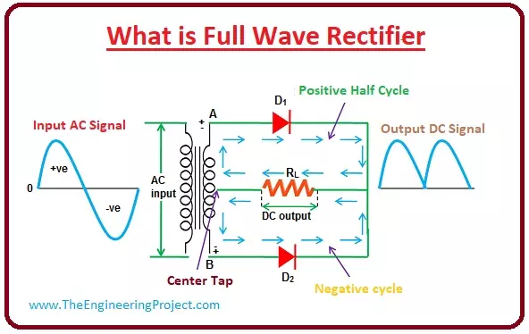
- The full-wave rectifier is such circuitry that transformed full sine waveform of the alternating current into the direct current.
- You can see from the given diagram that the rectifier circuitry transformed the complete alternating waveform into the direct current.
- There are 2 main types of full-wave rectification circuitries, first, one is centred tapped and other is bridge rectifier.
- We discuss both of them with the detailed.
- First, we discuss centre-tapped rectifier circuitry, to study this rectification first we discuss the centre-tapped transformer that is the important component of the centred tapped rectification circuitry.

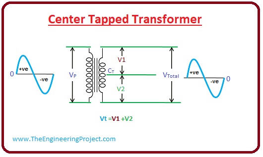
- As we already know that there are 2 main windings of the transformer, the first one is primary and other is secondary.
- If we connect an extra conductor at the center of the secondary winding, then the transformer is known as the centre-tapped.
- This transformer works like a normal transformer, but it provides an additional feature to the transformer.
- That is the voltage coming from the primary side to the secondary, will divide into 2 parts.
- One portion at the secondary is a positive half-wave and other is a negative half-wave, our total output voltage will be the sum of these 2 voltages.
Vt = (V1 + V2)
- This feature of the centred tapped transformer is used in the rectification process.

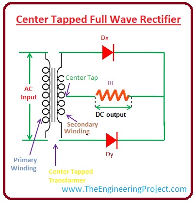
Center Tapped Full Wave Rectifier
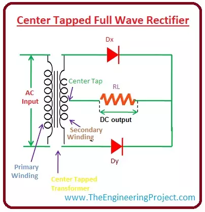
- In this type of the rectification circuitry, there is one centre-tapped transformer and 2 diodes are used for conversion of ac to dc.
- You can see from the circuitry that the input alternating supply is provided to the primary winding of the transformer and the at the secondary side an extra conductor is connected at the center of the secondary winding.
-
The central conductor divides the secondary winding into 2 parts, the first part of the secondary winding is connected with the diode (Dx) and other part connected with the diode (Dy).
-
Both of these diodes are also connected with the common resistor RL, that is load resistance it connect with the transformer by the tapped conductor.

Working of the Center Tapped Full-Wave Rectifier
- This rectifier circuitry used a centre-tapped transformer for the conversion of the alternating current into the direct current.
- When the voltage comes at secondary winding from the input windings it distributed into the 2 parts first one is positive and other is negative.
-
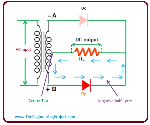
When the first half of the sine wave comes at the point A of the secondary it is at a positive potential and point B is at a negative potential, and the centre conductor is at 0 voltage level.
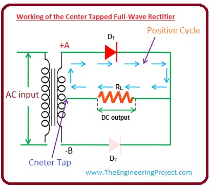
- The point A is joined with the anode of the diode Dx and the point B is joined with the cathode of the Dx, this assembly tells that the diode Dx is forward biased condition, and current starts to flow.
- You can see from the circuitry that point B is joined with the anode of the Dy and point A of the secondary windings is connected with the cathode of the Dy.
- So diode Dy has reversed mode in the positive half of the supply and current does not flow through Dy.
- This rectified current than goes to load resistor RL, and then to the secondary winding.
- We can conclude that when positive half of the input comes then there will be zero current through Dy, as it is reversed biasing and Dx is in forward biasing so current passes through this diode.
- When negative half comes at the secondary winding, the Point A is at a negative potential, and point B is at a positive potential.
- The negative point A is joined with the anode of the Dx and positive point B is linked with the cathode of the Dx.
- The diode Dx is in reverse mode so current does not pass through it.
- The positive point B is joined with the anode of the diode Dy and point A is joined with the cathode of the Dy.
- The diode Dy is now forward biasing so current will flow this diode.
- Due to the reverse biasing of the diode Dx, during negative half, the current does not pass through the upper portion of the circuitry and current flows in the lower part.


- So, in case of the negative half of wave-current pass through the Dy that is in the forward-biased state.
- In conclusion, we note that the diode Dx operates in the positive half of the input supply and Dy operates in the negative half of the supply.
- In this way, both parts of the input converted into the dc voltage. The given diagram explains the complete conversion of the input supply.

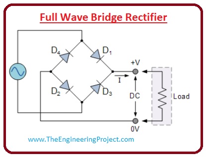
Full Wave Bridge Rectifier
- It is the other category of the full-wave rectifier circuitry, in this circuitry, there are 4 diodes are connected in bridge-like arrangements, and converts ac input supply into the direct current supply.
- Its main benefit is that there is no need of special centre-tapped transformer for this circuitry, that makes it simple and less costly.
- We can see from the circuitry that 4 diodes are connected in a sequence, and only 2 diodes work for each half of the input supply.
- When there is positive half at the circuitry diode D1 and D2 will operate and negative half diodes D3 and D4 will work.

- When positive half of the input sinewave comes than diodes D1 and D2 works and positive half of the supply converts into the dc. The given diagram shows the direction of the current.
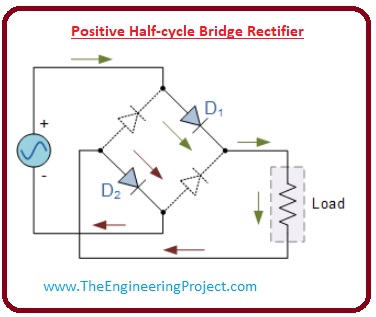

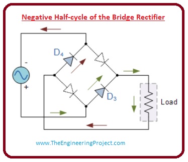
- During the negative half of the supply only diodes, D3 and D4 will operate as they are in the forward-biased direction.
- As D1 and D2 work in the positive half and the D3 and D4 works in the negative half, our output will be full-wave dc.

×
![]()


