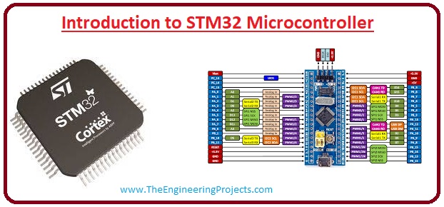
In today's post, we will have a look at its working, features, pinouts, applications and some other related parameters. So lets with the Introduction to STM32 Microcontroller.
Introduction to STM32 Microcontroller
- The STM32 is a type of microcontroller that offers the ARM Cortex-M thirty-two bits processor.
- This type of microcontroller is mostly used in different engineering projects.
- This module has numerous series and parallel combinations for the connections so many other electronic devices can be linked with this module such as LCD display, a sensing module, electrical motors, etc.
- All modules of the STM32 are mounted with interior memory storage and random access memory (RAM).
- The price of some other STM family modules is higher. And STM series like STM32F0 and STM32F1 is consists of the twenty-four megahertz and sixteen pinouts.
- The STM32H7 modules use four hundred megahertz and have two forty pinouts at its casing.
- The sophisticated modules of STM series are used for FPU floating-point units applications where there is need of some special arrangements.

Pinout of STM32 Microcontroller
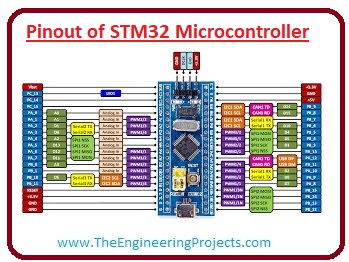
- Now we discuss the pinouts of STM32 with the detailed, that is described here with the detail.
| Pin names | Pin Types: | Parameters |
| IOREF | It is power pinout. | At his pinout reference, 3,3 volts are applied. |
| RESET | It is power pinout. | This pinout is used to reset the controller. |
| +3.3 volts | It is power pinout. | At this pinout, 3.3 volts are applied as output that can also be used to give input to the microcontroller. |
| +5 volts | It is power pinout. | This pinout is only for five volts outputs. |
| GND | It is power pinout. | It is ground pinout. |
| A0-A1 | Analog Pins and I2C | At this pinout, analogue voltage is found. |
| A4 and A5 | Analog Pins and I2C | At this pinouts, I2C transmission of data is done A4 is SDA (Serial Data) pinout and A5 is SCL (Serial Clock) pinout. |
| D8-D15 | Digital Pins and SPI | These are digital GPIO (General Purpose Input/Output) pins. |
| AVDD | Digital Pins and SPI | At this pinout, the analogue reference voltage is applied. |
| GND | Digital Pins and SPI | It is ground pinout. |
| D13, D12. D11 and D10 | Digital Pins and SPI | These pinouts work as SCK (serial clock), MISO (master in slave out), MOSI (master out slave in) and CS pins respectively for SPI communication. |
| D0 to D7 | Digital Pins and USART | These pinouts are Digital GPIO (General Purpose Input/Output) pins |
| D0 and D1 | Digital Pins and USART | These pins act as Rx (receiver) and Tx (transmission) pins respectively for USART communication. |
| PC0, PC1, PC2, PC3, PC10, PC11, PC12, PC13, PC14, PC15 | These are Port pinouts | All these are digital pinouts of port c of the module. |
| PD2 | It is Port pinouts | It is the input and output pinout of Port D. |
| PA0, PA1, PA4, PA13, PA14, PA15 | These are Port pinouts | All of these are input/output pinouts of Port A. |
| PB7, PB8 and PB9 | These are Port pinouts | These are input/output pinouts of PORT B. |
| PH0 and PH1 | These are Port pinouts | These are input/output pinouts of port H. |
| VBAT | It is power pinout. | This pinout used to provide power to the module form the battery. |
| +3.3 Volts | It is power pinout | This pinout provides 3.3 volts as output that can be used to power up the module. |
| +5V | It is power pinout | It is five volts output supply pinout. |
| VIN | It is power pinout | It is unregulated input power pinout. |
| RESET | It is power pinout | It used to Resets the microcontroller. |
| IOREF | It is power pinout | This is reference voltage pinout. |
| PC4, PC5, PC6, PC7, PC8, PC9 | These are Port Pinouts | These are the input and output pinout of Port C. |
| PA2, PA3, PA4, PA6, PA7, PA10, PA11 and PA12 | These are Port Pinouts | These are the Port A inputs and outputs pinouts. |
| PB1, PB2, PB3, PB4, PB5, PB6, PB8, PB9, PB10, PB12, PB14, PB15 | These are Port Pinouts | These are the Port B inputs and output Pinouts. |
| U5V | It is power pinout | It is five volts power pinout. |
| GND | It is power pinout | It used to ground the controller. |
| U5V | It is power pinout | It is analog ground pinout. |
- Now we see the pinout diagram of STM32.

Applications of STM32
- These are some practical applications of STM32 that are described in detail.
- This module is used in less power consuming hand-held electronic devices.
- This microcontroller is also used in Robotics and different electronic projects.
- It is also used in system automation.
It is a detailed tutorial on the STM32 I have explained each and everything related to this microcontroller. I tried my level best to describe this module in the simplest way, but still, if you have any question and query about this module please as in comments. Thanks for reading. see you in the next tutorial. Have a nice day.


 STM32 Projects
 williamjones
 0 Comments


 2.3k
2.3k
 953
953
 921
921
 2.1K
2.1K

