


Controlling 7-Segment Display with PLC Ladder Logic


Hi, my friends, and I hope you are doing great today! We have today one interesting topic that you have seen everywhere you go, but you might not notice it! That is what the so-called binary coded decimal (BCD) is. So what’s that? Well! When you are waiting for your turn at the front of a wicket in the bank. You see 7-segmented displays that show numbers in digits. So how do these counter displays work? The BCD is the idea behind how these displays work. Numbers can be represented in many formats. Some of these formats are readable for the public which is the decimal pr the digits 0, 1, 2, .., 9. On the other side, there is another number format which is not readable to general people. Still, it is essential for computation and computer processing like binary format and hexadecimal formats. Without going deeply into number format, we want to let you guys know that. The numbers are mostly displayed for people in digits or decimal format 0-9 but processed in binary by computer. So converting that binary format to decimal format is crucial in such an application. This tutorial shows you how plc can help perform as a BCD controller.
BCD representation
As we have two formats to convert from to, figure 1 shows the digital format 0-9 that are displayed in the first column while the binary equivalent is represented by 4 bits A, B, C, and D. but we need to represent the 7 segment operation how it looks like and how it has been implemented in the past and in the present using the evolving development in computation and electronics. From there, we can jump to how the PLC can control the 7 segments and that kind of display.

The 7-segment display
Figure 2 images a 7-segment display that shows 7 LEDs a, b, c, d, e, e, and g. for displaying a digit from 0 to 9 we need to illuminate some of these lLEDs to shape the required digit.

For example, digit 1 can be formed by lit LEDs b and c while all other LEDs are off. Also, table 1 shows the states of the 7 LEDs for digits from 0 to 9.


Table 1: the equivalent states of the 7 segments for digits 0-9
digit |
a |
b |
c |
D |
e |
F |
g |
0 |
1 |
1 |
1 |
1 |
1 |
1 |
0 |
1 |
0 |
1 |
1 |
0 |
0 |
0 |
0 |
2 |
1 |
1 |
0 |
1 |
1 |
0 |
1 |
3 |
1 |
1 |
1 |
1 |
0 |
0 |
1 |
4 |
0 |
1 |
1 |
0 |
0 |
1 |
1 |
5 |
1 |
0 |
1 |
1 |
0 |
1 |
1 |
6 |
1 |
0 |
1 |
1 |
1 |
1 |
1 |
7 |
1 |
1 |
1 |
0 |
0 |
0 |
0 |
8 |
1 |
1 |
1 |
1 |
1 |
1 |
1 |
9 |
1 |
1 |
1 |
0 |
0 |
1 |
1 |
Also, guys, Figure 4 Combines the digits, the equivalent binary inputs, and the outputs represented by the states of the 7 LEDs to form the number or the digit we need to display.

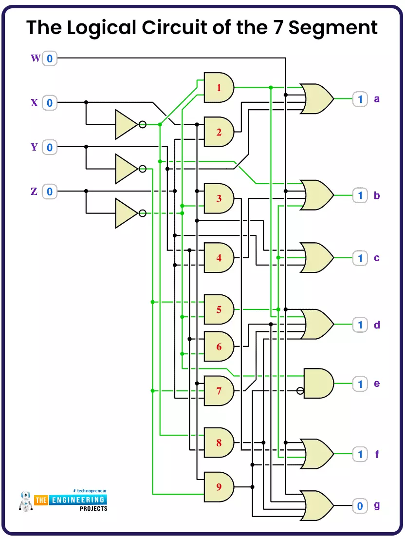
The logical circuit of the 7 segment
The BCD to 7-segment decoder has been implemented by combining logic gates, as shown in figure 5.
This decoder is now available in the market as an integrated circuit IC as shown in figure 6. As you see, guys, the IC has the 4 binary inputs, and all the 7 LEDs, a, b, c, d, e, f, and g, come out as an output signal that will be connected to the 7-segment display to show the numbers or digits. So now it is the time for my friends to show how PLC can perform this piece of cake job by assigning 7 inputs from its input module to the 7 outputs that will be directed or connected to the 7-segment display. So let’s go doing this mission.

BCD to 7 segments using PLC
You can see, guys the project we are going to implement using ladder logic programming includes eight inputs and eight outputs. The requested digit can be formed by set the related inputs to high, and the outputs will be set accordingly. Then the outputs are connected to the 7 segments to display the requested digit.

The logic of the BCD to 7 segment project
First of all, guys, look at figure 8, which depicts how we design such a system. The inputs to the 7 segments IC will be the 4 binary bits A, B, C, and D, which are coming from the PLC outputs. These 4 bits will decide the states of the 7 outputs a, b, c, d, e, f, and g, which will be forwarded to the 7-segment display to display the target digit 0 to 9.

The logic is pretty simple my friends; it is straightforward because all that we need to do is to relay the inputs the user or the operator requested via the inputs switches of the PLC to the outputs of the PLC as shown in figure 9.

The ladder logic code of the project
Figure 10 shows the rungs of the ladder program of the BCD to 7-segment converter. As you see, guys, the code is very easy. It is nothing but assigning each input to its mate of the output for the eight bits that will be forwarded to the 7 segments to form the number or the requested digit.

Testing the BCD to 7-segment decoder by PLC
Figure 11 shows one of the tests to display digit 7. You can see, guys, that the output was 11100000, equivalent to the digit 7. That output will be forwarded as an input to the BCD to 7 segment IC. That results in setting the outputs a, b, c, d, e, f, and g and, in turn, displaying the digit 7 on the 7-segment screen.

Testing the hexadecimal format
The project can display the hexadecimal format also, as shown in Figure 12, which shows the Hexadecimal value FF that is equivalent to 11111111 in the binary format. So all the outputs are high, as shown in the results.

Finally, I would like to thank you all for following the tutorial until the end. I hope you enjoyed the idea and went step by step to code the project and practice simulating it as usual ti boost your capability of the PLC ladder logic programming.


