Hello, my friends, again we are back and enjoying one of the new tutorials in our ladder logic programming series. The tutorial we are here to present comes with a new project: dual compressors management using PLC. In that very project, you are going to learn how to divide the process between two actuators aiming to prolong the lifetime of the equipment and fulfill the processing requirements. as we used to do every tutorial, will go through the project. Understand the requirements, and design for the solution. And then code the ladder logic program of the solution and for sure enjoying simulating the code to validate the functionality of the proposed code. So without any more delay, let’s get started on our project.
What’s dual compressors project
The picture of the project shown in figure 1, can tell everything about the project including the sensors and actuators. The project utilizes two compressors to fill the tank with gas. Sometimes one compressor is enough, and some time needs to have both compressors work together to compensate for the heavy-duty demand. So now, which compressor will be in charge based on the demand and for prolonging the equipment’s lifetime? These kinds of problems are our mission to figure out a workable ladder logic program to handle the whole process. The image shows all details you need guys to complete the project. Inputs and outputs, switches, push buttons, indicating lamps to tell process status, screens and BCD Displays.
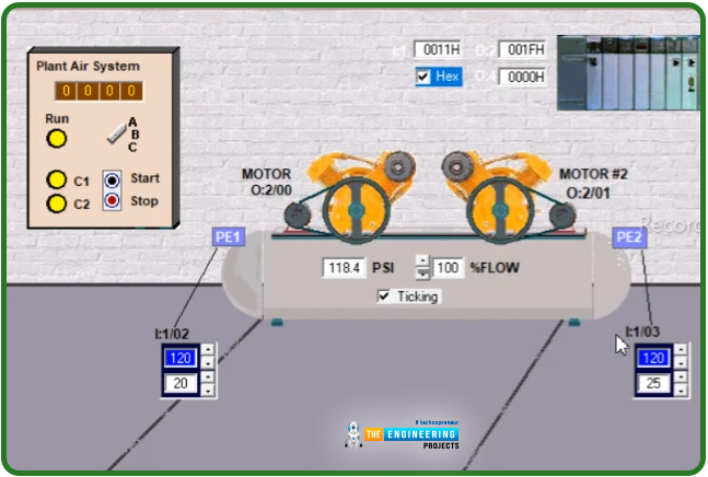
Project inputs and outputs address and description
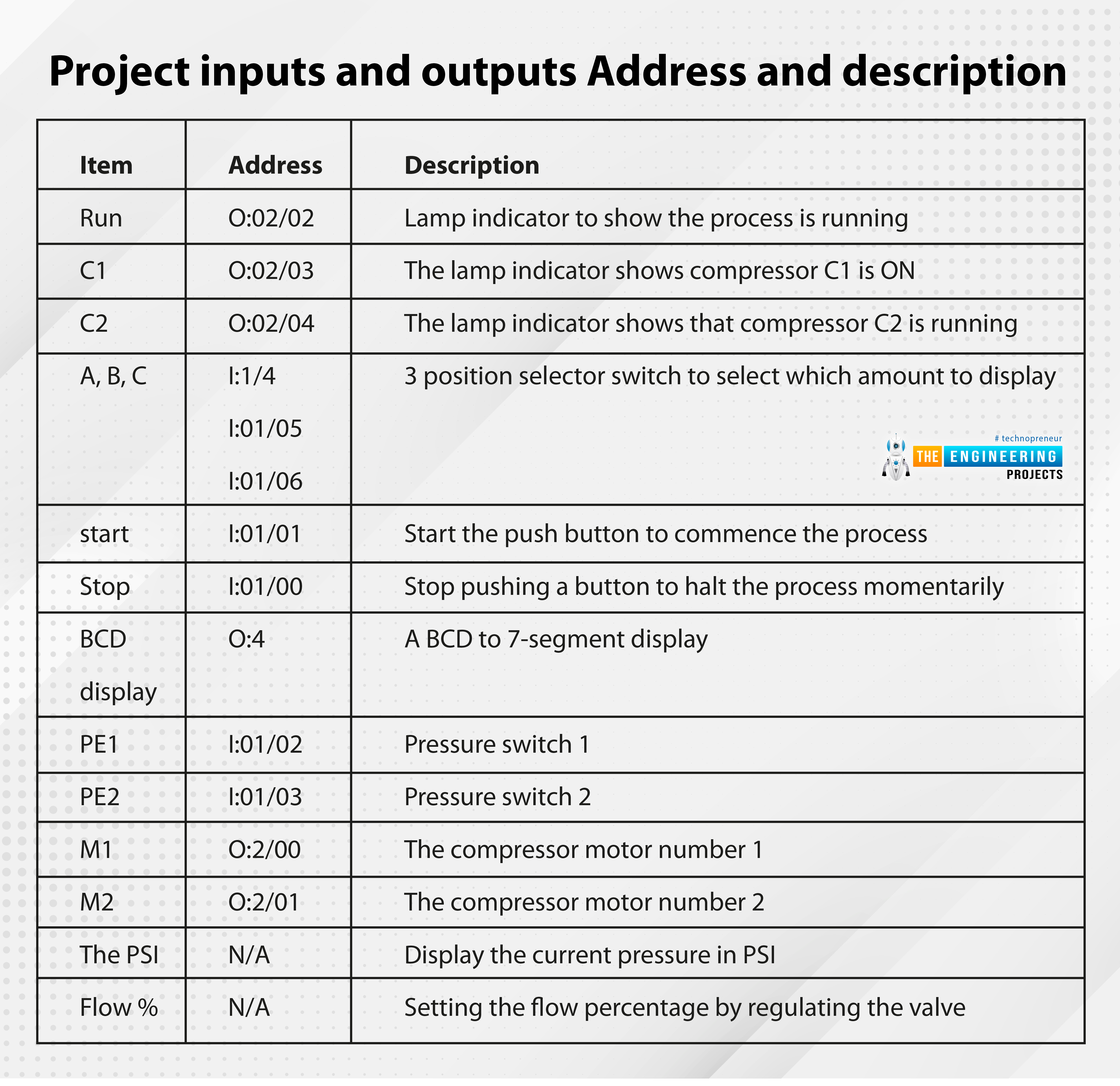
Table 1 shows the inputs and outputs of the process, telling the addresses and the description of each component. The first column list the inputs or the outputs of the process, column 2 lists the dedicated address of the Ios, and the description of these Ios is told by the 3rd column.
Item |
Address |
Description |
Run |
O:02/02 |
Lamp indicator to show the process is running |
C1 |
O:02/03 |
The lamp indicator shows compressor C1 is ON |
C2 |
O:02/04 |
The lamp indicator shows that compressor C2 is running |
A, B, C |
I:1/4 I:01/05 I:01/06 |
3 position selector switch to select which amount to display |
start |
I:01/01 |
Start the push button to commence the process |
Stop |
I:01/00 |
Stop pushing a button to halt the process momentarily |
BCD display |
O:4 |
A BCD to 7-segment display |
PE1 |
I:01/02 |
Pressure switch 1 |
PE2 |
I:01/03 |
Pressure switch 2 |
M1 |
O:2/00 |
The compressor motor number 1 |
M2 |
O:2/01 |
The compressor motor number 2 |
The PSI |
N/A |
Display the current pressure in PSI |
Flow % |
N/A |
Setting the flow percentage by regulating the valve |
The project coding
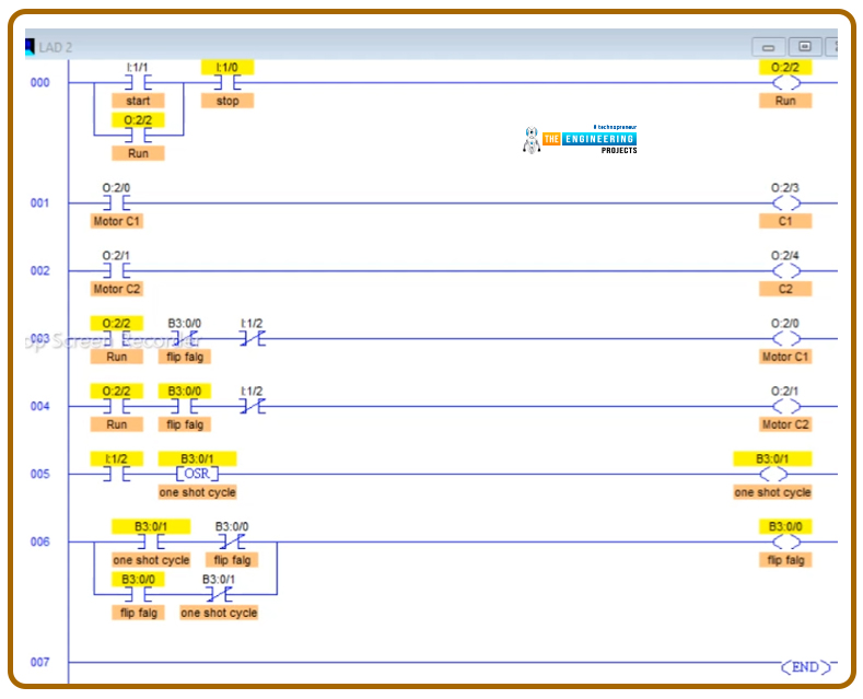
As I want you to learn how to apply the divide and conquer technique of programming, I’d like us to divide the project into parts, small, simple tasks. By combining them all, we get the whole process done. So now let’s start by running a single compressor and stop it based on user requests having the process status shown by indicators and displays that we have and listed in table 1 above. Figure 2 shows the code for running in single actuator mode. So one compressor will take charge and start by hitting the start push button while it is stopped either by hitting the stop push button or by reaching the high-level pressure indicated by sensor I:1/2. Also, you notice my friends, the lamp indicators for showing the process status, like Run status and which compressor is in charge now.

Switching between the two compressors
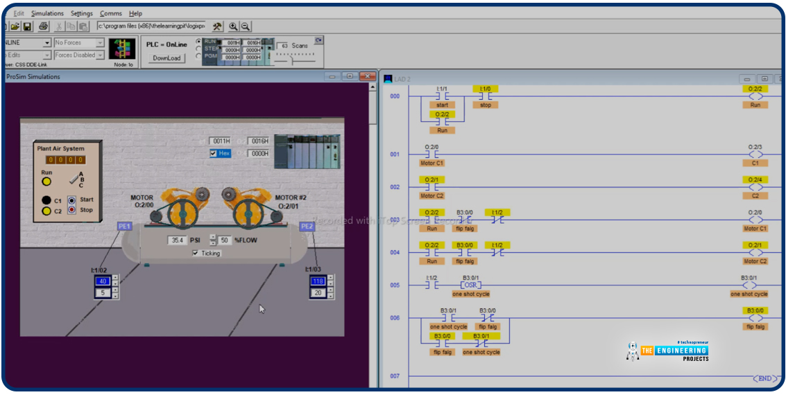
Realizing the dual operation concept in which we should use both compressors equally one for each cycle, figure 3 shows the ladder logic code to do so. You can see the project is getting bigger by adding more tasks. but let’s go through the line we have written so far, as shown in the figure below. Firstly we have latched the run status by hitting the start push button in the first runge. And the coil of the first compressor activates the indicator lamp of the first compressor as in the 2nd range. Similarly, the second compressor relay coil energizes its indicating lamp. In the fourth and fifth rungs, the formula is based on which the program can decide which compressor to run. Each compressor depends on its pressure switch. Compressor 1 works as long as the pressure measured by PE1 is within its limit, and compressor 2 works as long as the pressure measured by PE2 is within its limit to run. However, you notice, guys, there is one bit which is B3:0/0, which we have used to decide which compressor to choose to run each cycle. That is why it is XIC for one and XIO for the other compressor guy. But wait, how will we know the cycle ends, and a new cycle is to begin? Well! It’s the sixth runge that reads the one shot of the I:1/2 to change the status of B3:0/1 each cycle and, in turn, change the compressor. And notice, guys, the most intelligent runge, the last rung that flips the flag B3:0/0, which is responsible for flipping the operation from one compressor to the other. Now, the time to test all that we have done of coding comes to see if it is correct or needs to amend for correction. So let’s go test our ladder logic code.
Testing the dual compressor operation
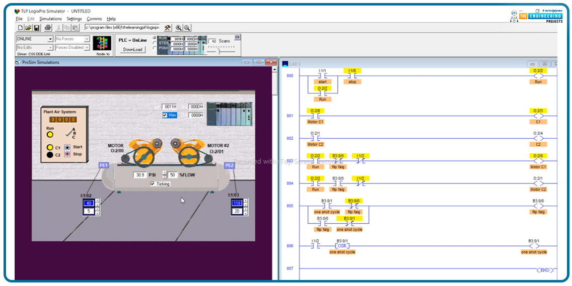
Figure 4 shows the first case when we hit the start push button, compressor C1 started working. And it keeps working as long as the pressure PE1 reads is less than 40 PSI, as you can see in the figure below. Compressor C1 is running and sufficient to fulfill the process requirements. Also, my friends, see the control panel showing the status of the running compressor is ON, highlighted in yellow, while the other compressor guy is off as indicators tell.
In another case, figure 5 shows when both compressors are off because the operator hit to stop the push button to halt the process. See the indicators of both compressors are off, and the run process is ON, waiting to hit start to resume the process.
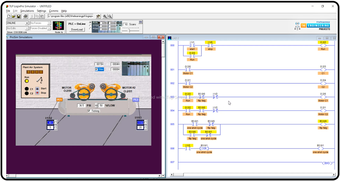
Now, time to start a new cycle, remembering the last time compressor C1 was working. Notice, guys, our code’s success in switching to the other compressor, C2. The flip flag in the last range turns on to flip the compressors from one to the other smartly. Also, the indicator panel shows the compressor C2 lamp is highlighted while the other guy’s light is turned off.
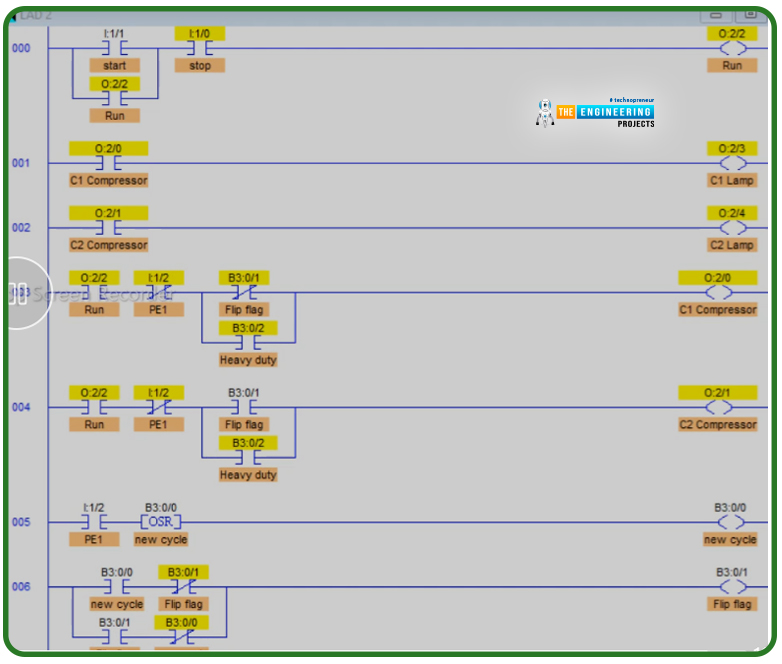
One last thing to consider, my friends, is when we run at a heavy demand of using the tank. One compressor won’t be enough to fulfill the heavy-duty process in this condition. Therefore, we need to have one case to run compressor C1, the other to switch to compressor C2, and the third case at heavy-duty we need to run both compressors C1 and C2 together to fulfill the heavy demand. Notice my friends in rungs 003 and 004, the change we have made is just adding a parallel branch to override the flag switch to give a chance for both compressors to work regardless of the flag when heavy duty is on that detected by PE2 pressure switch when it lowers than 95 PSI.
Testing the heavy-duty case
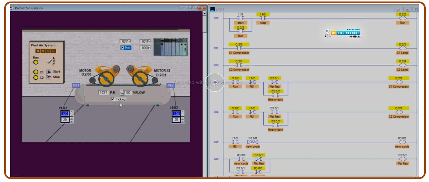
Figure 8 shows the case of running under high demand and reaching toe heavy-duty operating conditions. See how successfully our ladder logic program can run both compressors to fulfill such heavy-duty conditions. Also, please notice that the indicator lamp of compressors C1 and C2 are on when the heavy-duty flange is on because the PE2 marked pressure under 95 PSI, the lowest pressure based on the setting on I:1/03.
At last, I would like to thank you, my friends, for patiently following me until the end of this tutorial. Hoping you have got some benefits and learnt some new practices with the project we went through in this tutorial. Please stay safe, and let’s meet soon with another tutorial to enjoy learning and practicing ladder logic programming.


 PLC Projects
 syedzainnasir
 0 Comments


