Hello friends, I hope you all are doing great. Today, I am going to share the new TM1638 LED&KEY Library for Proteus V1.0. The red LED&KEY board is the favourite front panel of Arduino makers: eight 7-segment digits, eight LEDs and eight push buttons, all driven by a single TM1638 chip over three wires. Now this TM1638 8-digit display module with buttons is ready for your Proteus simulations too: the digits glow, the LEDs light, and you can click the buttons while the simulation runs.
Behind the board sits our own model of the TM1638, written from the Titan Micro datasheet: the 3-wire bus framed by STB, the data, address and display-control commands, the 16 bytes of display RAM that this board splits between digits and LEDs, the eight brightness steps and the key scan that sends the buttons back to the Arduino. You get two devices, a Simple one with a live STATUS panel and an Advance one with a pop-up window and five test tools, and the demo runs TM1638plus on our Arduino UNO V4.0 with its serial monitor built into the board.
NOTICE: most display libraries for Proteus only show things. This one also listens: the eight buttons of the LED&KEY board work, and the model answers the Arduino's key reads bit by bit, exactly as the real chip does. It took our team a lot of hard work. Your feedback is the fuel that keeps us going, so please tell us what you think in the comments below or in the LCD Library board of our forum. And if our free libraries help you, you can buy us a coffee. So, let's get started with the TM1638 LED&KEY Library for Proteus V1.0:
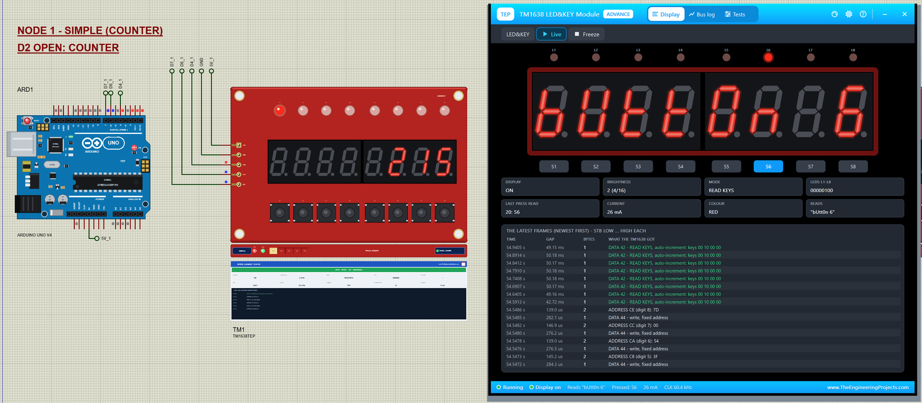
What is a TM1638 LED&KEY Module?
The TM1638 is an LED driver and key scanner from Titan Micro Electronics. It multiplexes up to eight digits of a common-cathode display, sets their brightness in eight steps and scans up to 24 keys. It talks over three lines: STB (strobe), CLK and DIO. STB goes low at the start of every transfer and high at its end, the bytes travel LSB first, and the chip reads DIO on the rising edge of CLK. DIO works both ways: when the Arduino asks for the keys, the TM1638 answers on the same line.
The module most people buy is the LED&KEY board: a red board of about 76 x 50 mm with two 4-digit 0.36" red displays in the middle, eight red LEDs L1 - L8 above them, eight push buttons S1 - S8 below them, the TM1638 on the back and a 5-pin header on the left edge: VCC, GND, STB, CLK and DIO.
| TM1638 LED&KEY module | |
|---|---|
| Driver | TM1638 (on the back) |
| Display | two 0.36" 4-digit 7-segment displays, red, with points |
| LEDs and buttons | L1 - L8 (red) above, S1 - S8 below the digits |
| Board | about 76 x 50 mm, four mounting holes |
| RAM | C0H - CFH: even addresses = the digits from the LEFTMOST, odd addresses = the LEDs |
| Buttons | on the TM1638's K3 line: 4 key bytes, byte i has S(i+1) in bit 0 and S(i+5) in bit 4 |
| Header | VCC, GND, STB, CLK, DIO (left edge) |
| Devices in this library | TM1638TEP (Simple) / TM1638ADVTEP (Advance) |
The TM1638 Commands
| First byte | Command | What it does |
|---|---|---|
| 40 | DATA (write, auto-increment) | The next bytes go to consecutive addresses |
| 44 | DATA (write, fixed address) | Every byte needs its own address command |
| 42 | DATA (read keys) | The chip sends 4 key bytes back on DIO |
| C0 - CF | ADDRESS | Followed by the bytes for this address (and the next ones) |
| 88 - 8F | DISPLAY CONTROL, on | Display on, brightness 0 - 7 (pulse width 1/16 ... 14/16) |
| 80 - 87 | DISPLAY CONTROL, off | Display off; the RAM keeps the digits and LEDs |
How TM1638plus Talks to the Chip
TM1638plus by Gavin Lyons is the library most LED&KEY examples use. It pulls STB low, shifts a command out with Arduino's shiftOut(), LSB first, and raises STB again. To write one digit it sends two frames: the data command 44 (fixed address) and then the address with the segment byte. With the "not a high-frequency MCU" setting on an UNO, the clock runs at about 60 kHz, far below the 1 MHz the TM1638 accepts.
Reading the buttons is the clever part. TM1638plus sends the data command 42, switches its DIO pin to INPUT and clocks in four bytes with shiftIn(). On the chip's side DIO is open-drain: the TM1638 pulls the line low for a 0 and lets the board's pull-up hold it high for a 1. Our model does the same, so the simulated ATmega328P reads exactly what it reads on a real module, and a module that is not wired reads as all ones.
What's New in TM1638 LED&KEY Library for Proteus V1.0
- The real module: the red LED&KEY board with its two displays, eight LEDs, eight buttons, the header on the left and the four mounting holes, drawn at 1.6 x its real size.
- Our TM1638 model from the datasheet: STB framing, the bytes LSB first, the data, address and display-control commands, auto-increment and fixed addressing, the power-up state.
- Working buttons: click S1 - S8 on the board while the simulation runs; the key read sends them to the sketch, bit by bit, on DIO.
- Digits and LEDs from one RAM: the even addresses light the digits, the odd ones the LEDs, as on the real board.
- Real digits: slanted segments and points, as bright as the eight pulse widths make them, in red, green, blue, yellow or white.
- The classic mistakes on screen: a dark display without displayBegin(), STB and CLK swapped, a reversed supply.
- Five test tools on the Advance device: Init check, 3-wire bus, RAM, Keys and Power.
- A TM1638plus demo on our Arduino UNO V4.0: a counter with a running LED, a keys mode, text, numbers and commands for every feature.
- A compact package: about 1.26 MB, without the C++ source code.
Two Devices: Simple and Advance
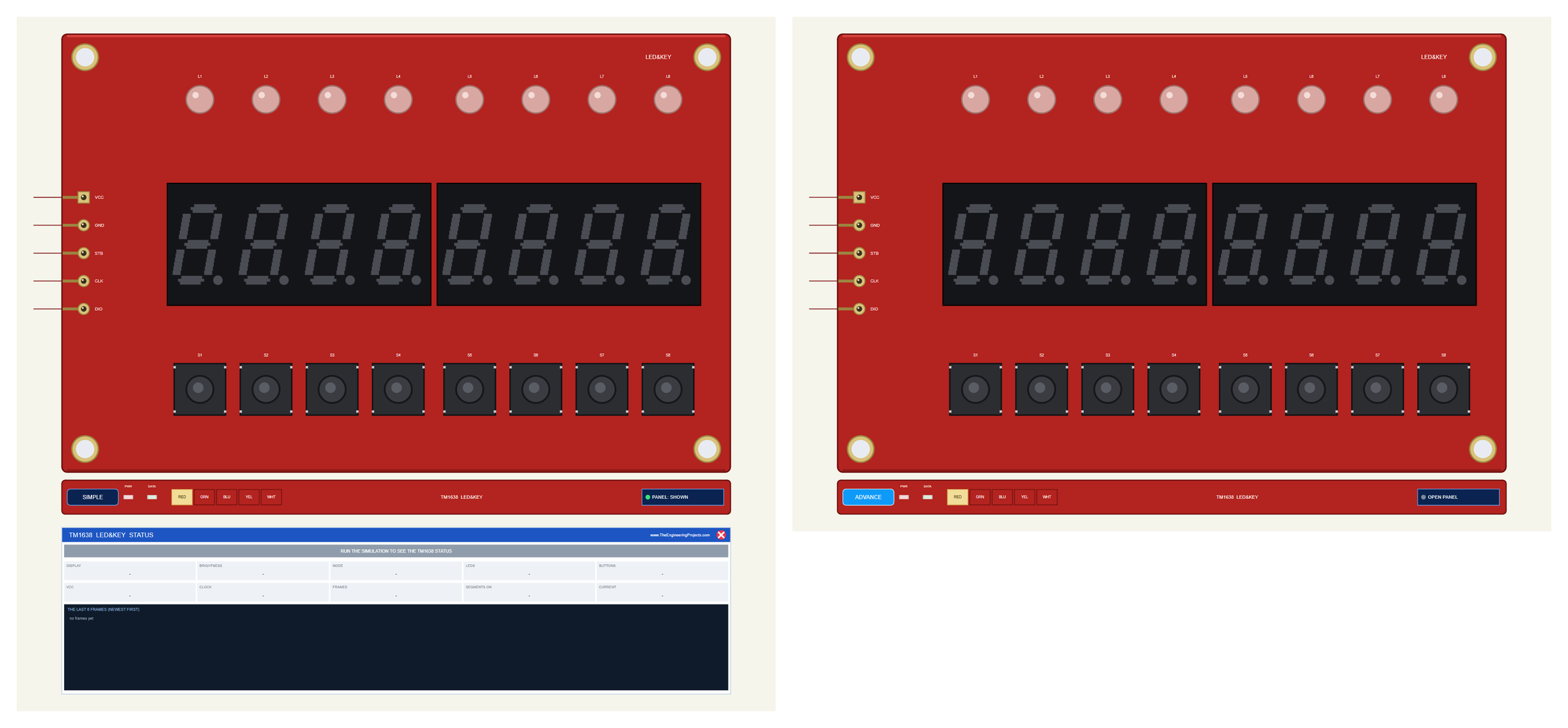
| Simple | Advance | |
|---|---|---|
| Device | TM1638TEP | TM1638ADVTEP |
| On the schematic | The module + the STATUS panel | The module only |
| Status | Banner, 10 readouts, the last 6 frames | A pop-up window: Display, Bus log, Tests |
| Buttons | Click S1 - S8 on the board | On the board or on the pop-up |
| Test tools | - | Init check, 3-wire bus, RAM, Keys, Power |
Download TM1638 LED&KEY Library for Proteus
Click the button below to download TM1638-LED-KEY-Library-for-Proteus-v1.0.zip (about 1.26 MB, without the C++ source code):
TM1638 LED&KEY Library for Proteus V1.0- README.txt: the devices, installation, the demo, wiring, the test tools and real hardware.
- Proteus Library Files:
TEPTM1638.LIBandArduinoV4TEP.LIBfrom our Arduino Library for Proteus V4.0. - Proteus Model Files:
TEPTM1638.DLLandTEPARDUINO.DLL. - Proteus Simulation:
TM1638-LED-KEY-ArduinoUnoV4.pdsprj,TM1638_Demo.hexand copies of both DLLs. - Arduino Code:
TM1638_Demo.ino(needs "TM1638plus" by Gavin Lyons from the Library Manager).
No Proteus yet? Read How to Download and Install Proteus 7 and 8. New to libraries? Follow How to Install a New Library in Proteus.
How to Install TM1638 LED&KEY Library for Proteus
- Close Proteus and extract the whole zip file, for example to your Desktop.
- Copy the two files from Proteus Library Files into the LIBRARY folder of Proteus (usually
C:\Program Files (x86)\Labcenter Electronics\Proteus 8 Professional\LIBRARY). - Copy
TEPTM1638.DLLandTEPARDUINO.DLLfrom Proteus Model Files into the MODELS folder. - Delete
TEPTM1638.IDXfrom the LIBRARY folder if there is one. - Start Proteus, press P and search for TM1638: the two devices show up.
Tip: keep the Proteus Simulation folder together, because the project needs its .hex file and the DLLs beside it. The library is tested in Proteus 8.5; Proteus 7 is not supported.
The TM1638 LED&KEY Module in Proteus
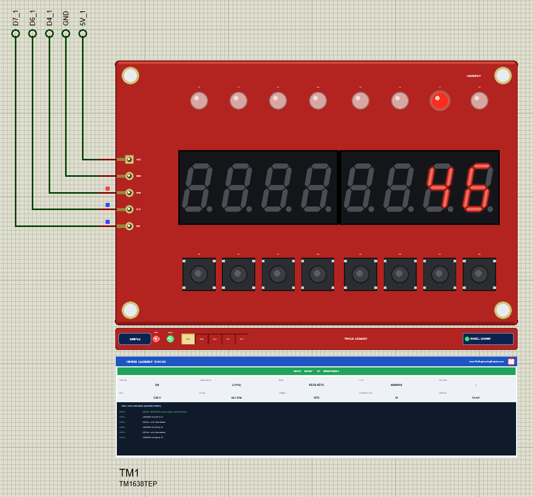
The module is drawn at 1.6 x its real size, which keeps its header pins on the Proteus grid and still fits two boards and two Arduinos on one sheet. While the simulation runs, each segment and point glows on its own, slanted like the real 0.36" digits, and the LEDs light red. Under the board, a TEP strip holds the SIMPLE / ADVANCE badge, a PWR LED, a DATA LED that flashes on every frame, the LED COLOUR selector for the digits and the panel button. The strip, its LEDs and the panels are TEP additions; a real module has none of them.
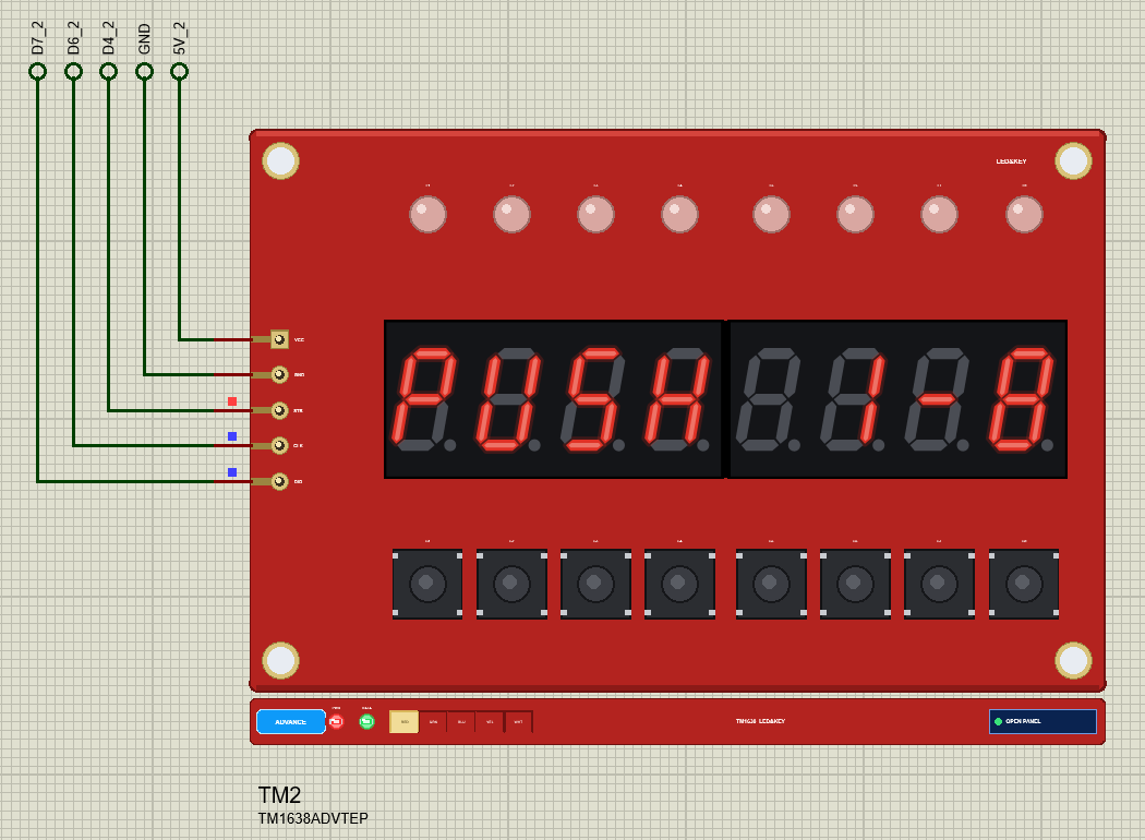
Pinout
| Pin | Function | Arduino UNO (demo) |
|---|---|---|
| VCC | The supply, 3.3 - 5 V | 5V |
| GND | Ground | GND |
| STB | The strobe: low for the whole transfer | D4 |
| CLK | The clock: the TM1638 reads DIO on its rising edge | D6 |
| DIO | Data in and out: the key bytes come back on this pin | D7 |
| Property | Values | What it does |
|---|---|---|
| PANEL | OPEN (default), CLOSED | Simple device only: the STATUS panel at the start |
| COLOUR | RED (default), GREEN, BLUE, YELLOW, WHITE | The digit colour; the selector on the strip changes it at Run |
Digits, Points and LEDs: The 16 Bytes of the TM1638
The TM1638 has 16 bytes of display RAM, C0H to CFH. The LED&KEY board wires them in an unusual way: the even addresses C0H, C2H ... CEH are the eight digits, C0H being the leftmost, and the odd addresses C1H, C3H ... CFH are the LEDs L1 - L8, where only bit 0 matters. In a digit byte, bit 0 is segment A, bit 6 is segment G and bit 7 is the point.
TM1638plus hides all of this. displayText() writes up to eight characters, and a dot in the text lights the point of the character before it. The demo clears the board first, so shorter texts leave no old characters behind:
  tm.reset();                                              // clear all 8 digits and LEDs first
  tm.displayText(s);
The LEDs have their own calls. setLEDs() takes one byte for all eight, and the demo's LEDS command passes it a hex number:
tm.setLEDs(strtoul(arg, nullptr, 16) & 0xFF);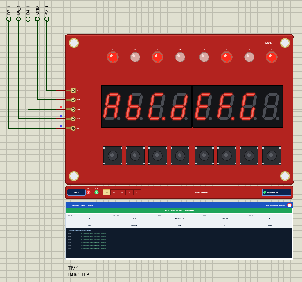
A single LED is setLED(position, value), with the position counted from 0, which is why the demo subtracts one from the LED number you type:
tm.setLED(n - 1, on ? 1 : 0);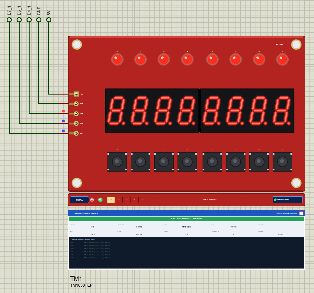
Numbers are just as easy. displayIntNum() right-aligns them without leading zeros, which is how the demo's counter and NUMBER command show them:
tm.displayIntNum(counter, false, TMAlignTextRight); // right-aligned, no leading zeros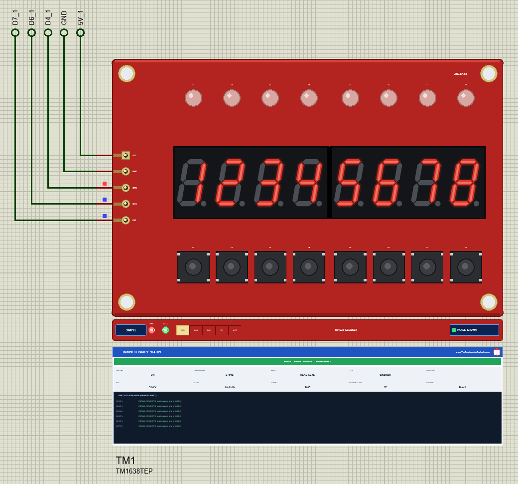
The Eight Buttons: How the Key Scan Works
The TM1638 scans its keys all the time on its own; the Arduino only has to ask. After the data command 42 the chip sends four bytes. The LED&KEY board connects all eight buttons to the K3 line, so in byte i the button S(i+1) is bit 0 and S(i+5) is bit 4. readButtons() folds the four bytes into one: S1 is bit 0 and S8 is bit 7. The demo asks 20 times a second:
if (millis() - lastRead >= 50) { // the buttons, 20 times a second byte b = tm.readButtons();In the keys mode each pressed button lights the LED above it and shows its number on the digits:
tm.setLEDs(b); // each pressed button lights its LED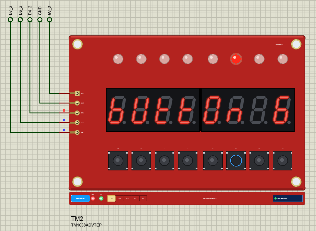
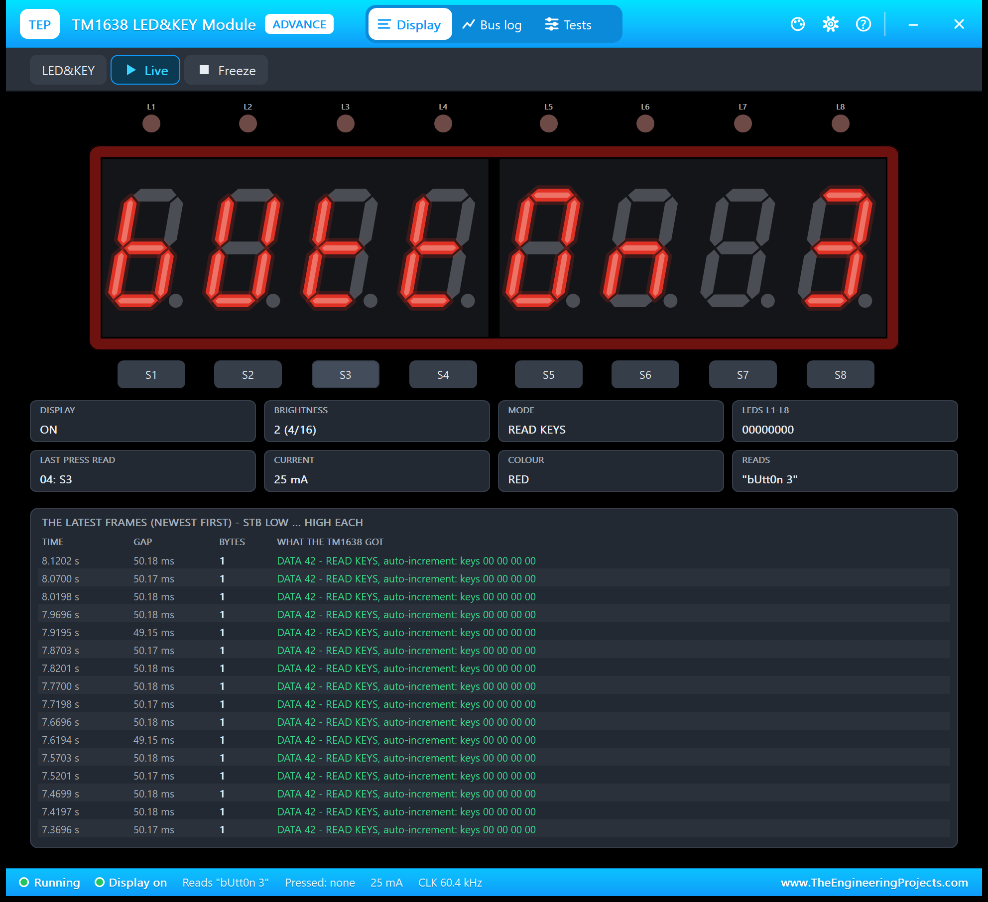
In Proteus you simply click a button on the board while the simulation runs. A short click holds it for at least 0.3 s of simulation, long enough for any sketch that polls the keys, and the button stays down as long as you keep the mouse button pressed. The Advance device has the same eight buttons on its pop-up, handy when the board is small on your screen:
Brightness and Display On / Off
The display-control byte carries the on / off bit and the brightness, a pulse width from 1/16 to 14/16 in eight steps. TM1638plus sends it with brightness(), and the demo's BRIGHT command maps straight onto it:
brightness = constrain(atoi(arg), 0, 7); tm.brightness(brightness);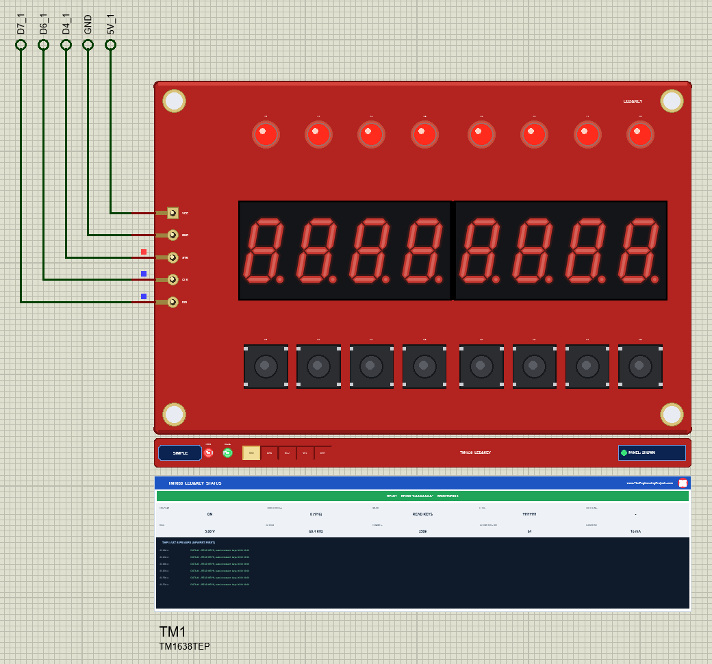
The Dark TM1638: Do Not Forget displayBegin()
A TM1638 wakes up with the display off and random bytes in its RAM. Nothing lights until the sketch sends a display control. displayBegin() does that and more: it switches the display on, sets the brightness and clears all 16 bytes. The demo calls it first thing in setup():
tm.displayBegin(); // display on, brightness 2, RAM cleared - without it: darkLeave it out and the model shows exactly what a real module shows: nothing, with the amber banner DARK - DISPLAY OFF: CALL displayBegin() on the Simple device and a line in the simulation log.
STB and CLK Swapped
Swap two wires, or two pins in the constructor, and every transfer turns into nonsense for the TM1638: strobes that cut bytes in half and clocks outside any frame. The demo's SWAP command uses a second TM1638plus object made the wrong way round:
static TM1638plus swapped(CLK_PIN, STB_PIN, DIO_PIN, false); // STB and CLK the wrong way round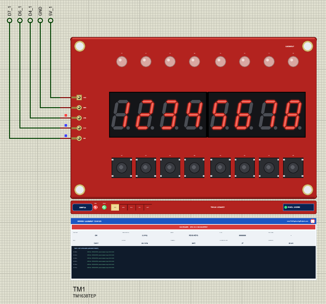
TM1638 Simple: The STATUS Panel
Under the Simple device a live TM1638 STATUS panel shows the banner (READY with what the digits read, or the problem in amber or red), ten readouts - DISPLAY, BRIGHTNESS, MODE, LEDS, BUTTONS, VCC, CLOCK, FRAMES, SEGMENTS ON and CURRENT - and the last six frames. The red X closes the panel; PANEL on the strip opens it again.
TM1638 Advance: The Pop-Up Window
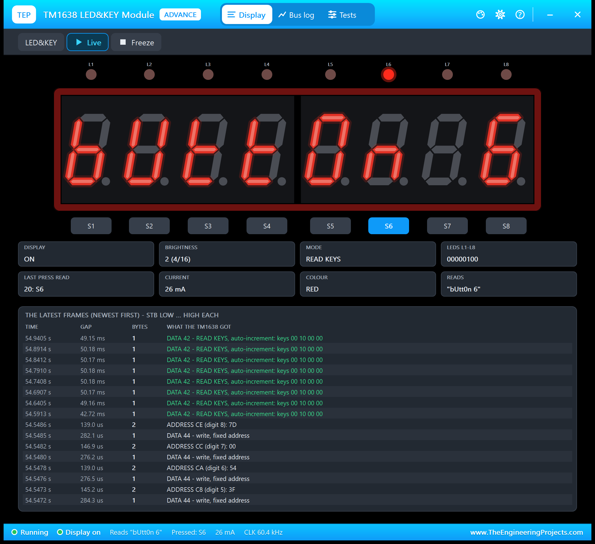
The Advance device opens a TEP pop-up window at Run with three pages. The Display page shows the LEDs and digits in large with the eight buttons under them, eight tiles - display, brightness, mode, LEDs, the last press the sketch read, current, colour and what the digits read - and the latest frames.
The Bus Log Page
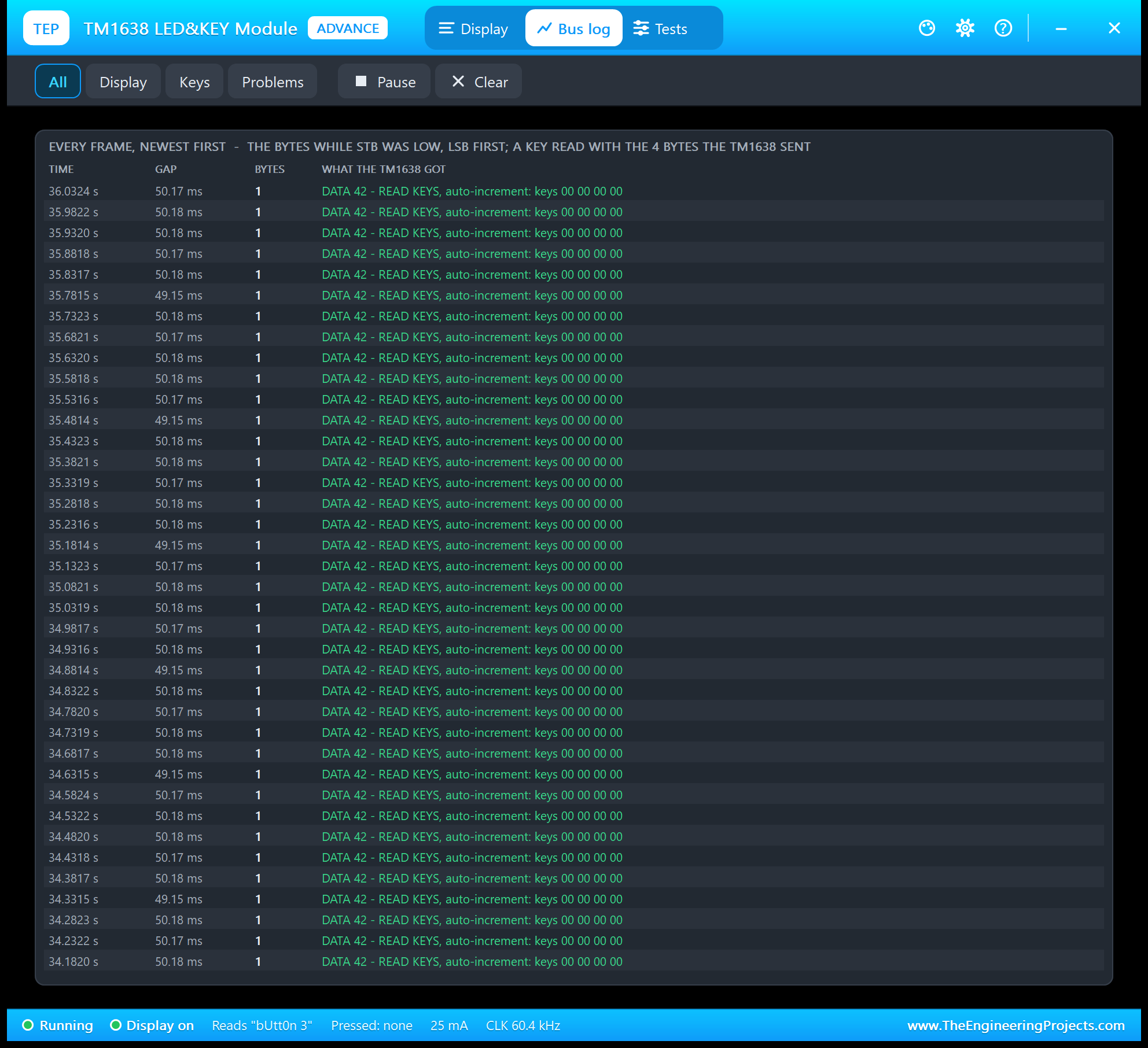
In the keys mode you see the sketch's key reads every 50 ms, and between them the data command 44 and the address frames whenever the digits or LEDs change. Filter it to the display writes, the key reads or the problems only; Pause freezes the list.
Five Test Tools for the TM1638
1. Init Check
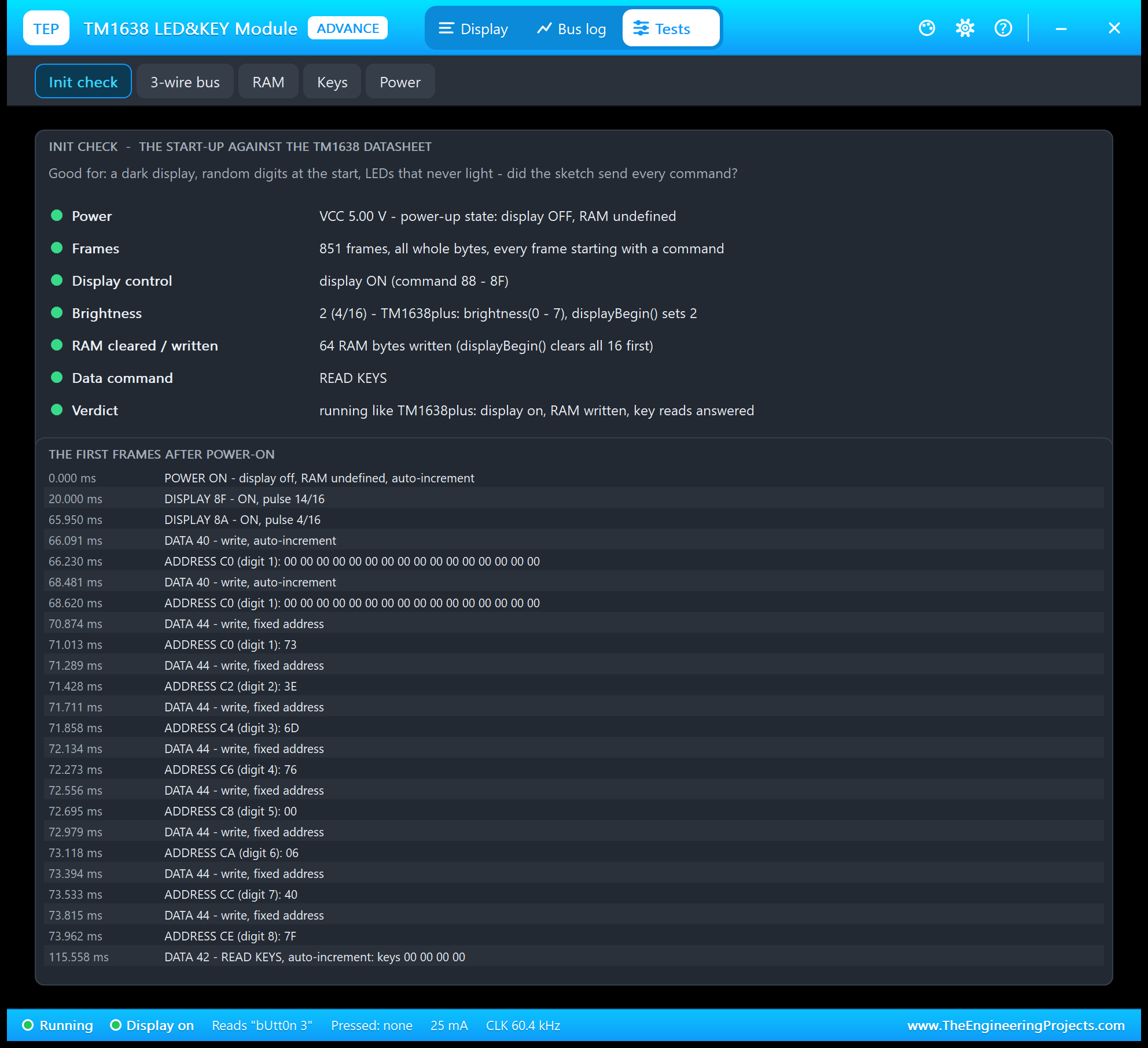
The start-up against the datasheet: the supply, the frames, the display control, the brightness, whether the RAM was cleared and written, the data command and a verdict. Below it, the first frames as the sketch sent them: the display control 8F and 8A, then the data command 40 with 16 zeros, which is displayBegin() at work.
2. 3-Wire Bus
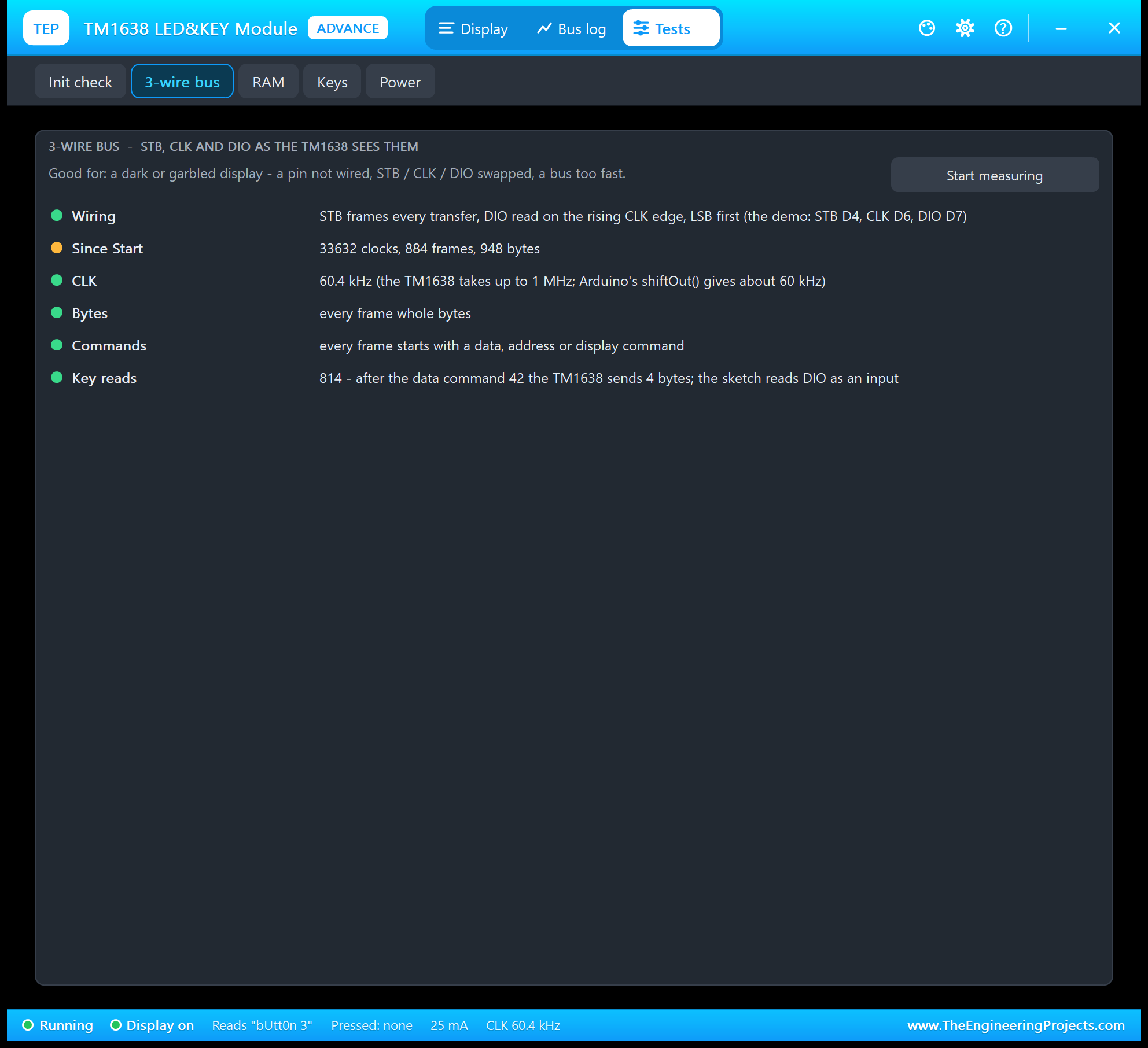
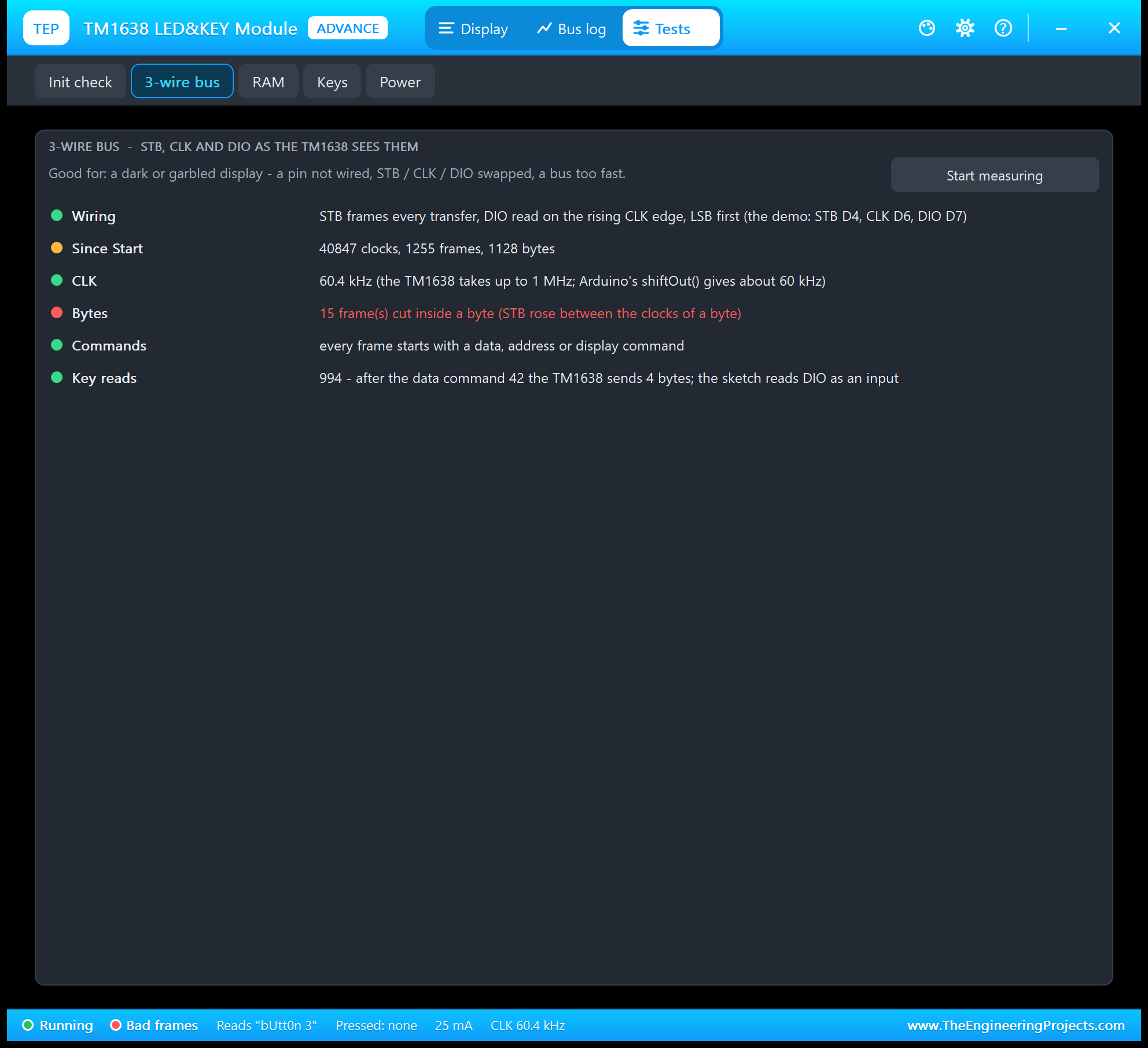
Good for a dark or garbled display: the clock against the TM1638's 1 MHz, bytes cut by STB, frames that do not start with a TM1638 command, and the key reads. TM1638plus on an UNO measured 60.4 kHz in our run.
3. RAM
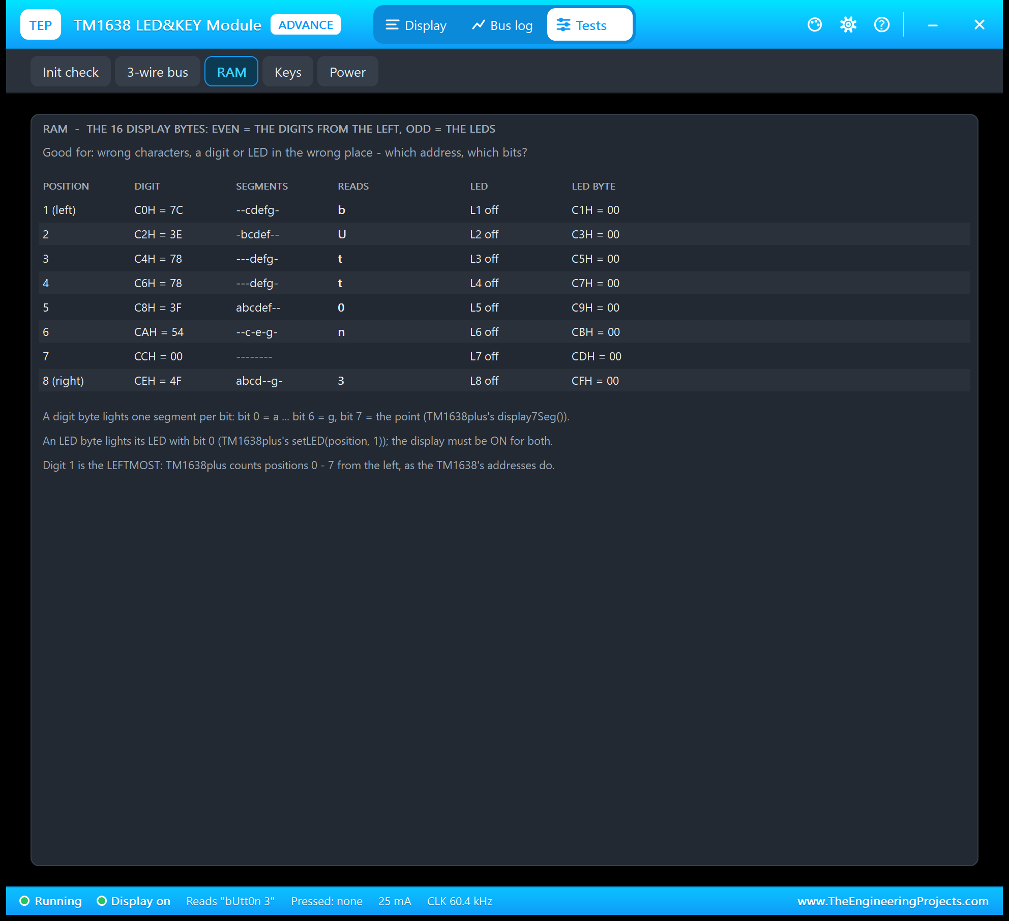
Good for wrong characters or a digit or LED in the wrong place: each position with its address, the byte, the segments it lights as letters, what it reads, and the LED next to it with its own byte.
4. Keys
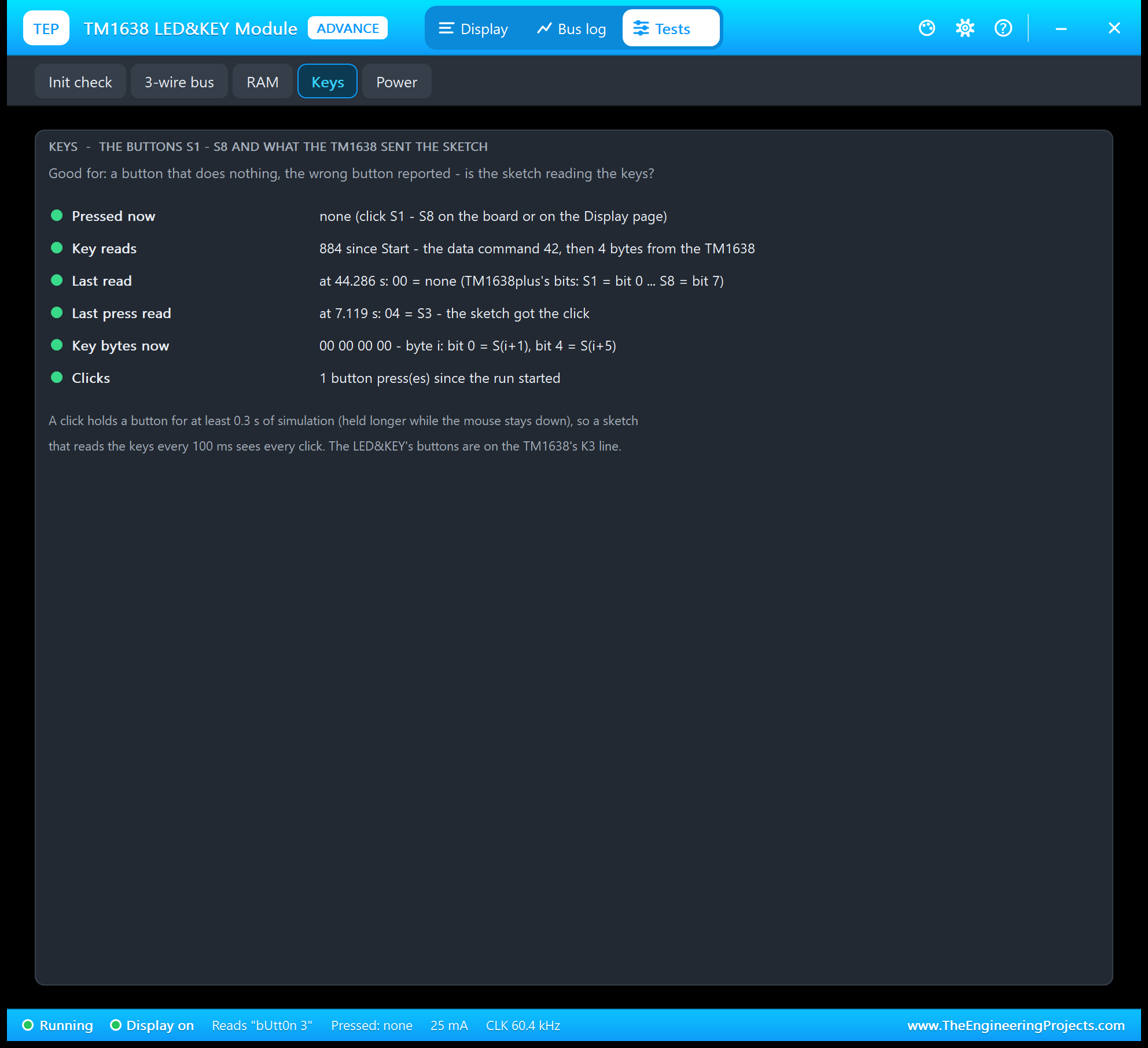
Good for a button that does nothing or the wrong button reported: if the key reads stay at zero, the sketch never asks; if the last press read shows the right button, the problem is in the sketch's logic, not in the wiring.
5. Power
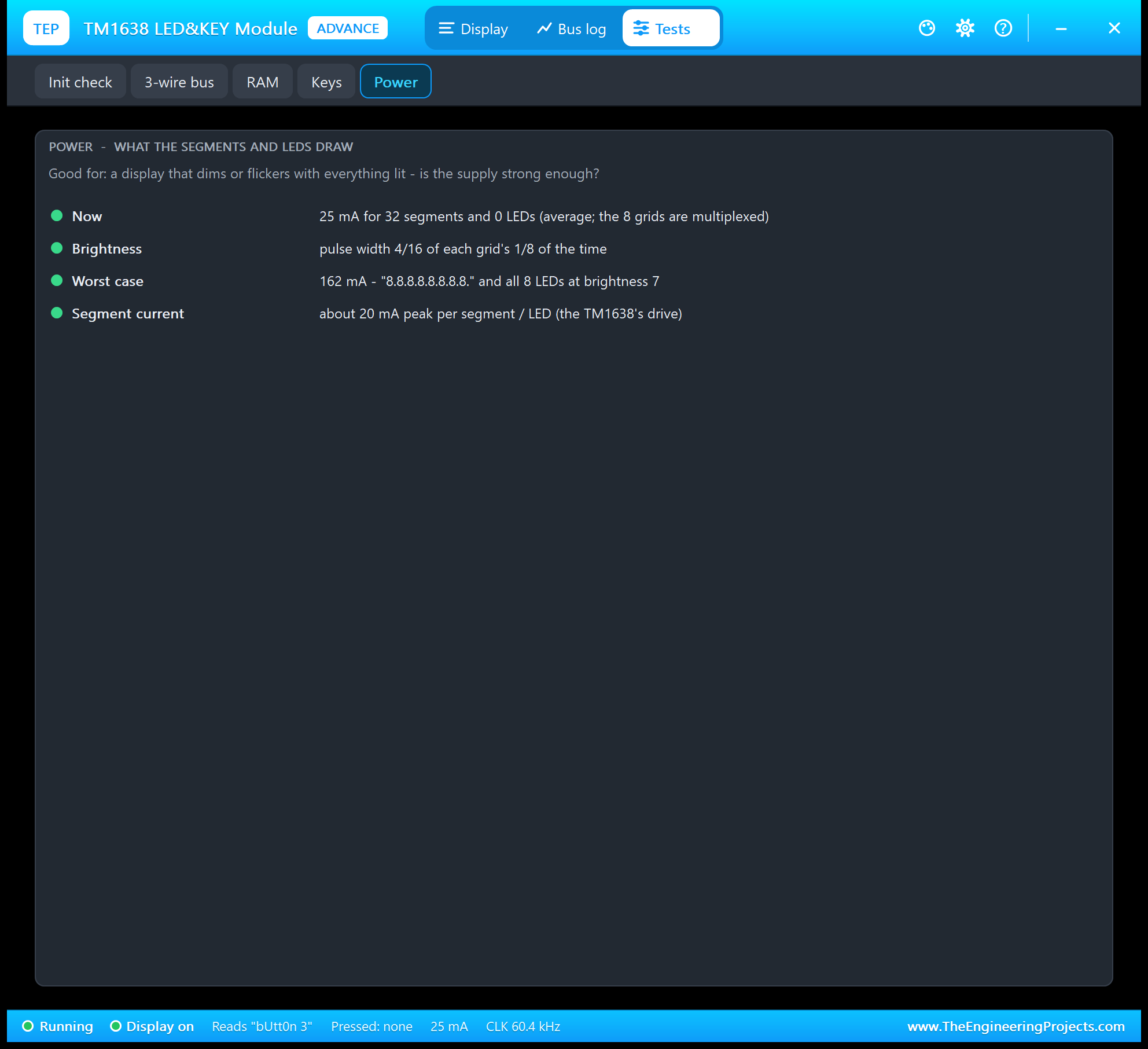
Each lit segment or LED gets about 20 mA while its grid is on, and the TM1638 scans eight grids, so it averages the pulse width / 8 of that. Everything on at brightness 7 draws about 162 mA, still fine from an UNO's 5V pin.
TM1638 with Arduino in Proteus
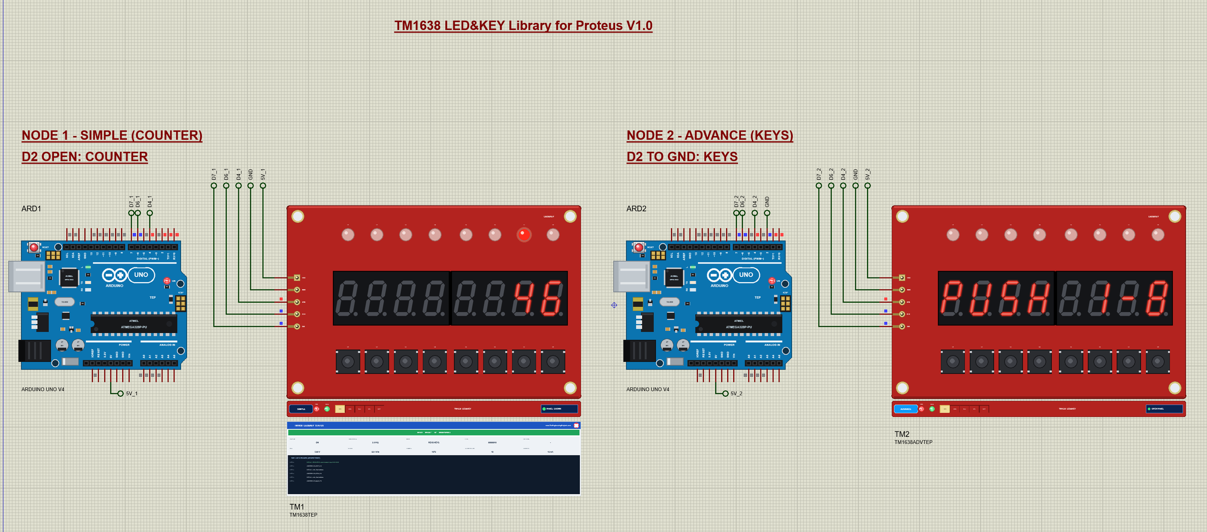
Open TM1638-LED-KEY-ArduinoUnoV4.pdsprj. Two Arduino UNO V4.0 boards from our Arduino UNO Library for Proteus V4.0 run the same sketch: with D2 open it counts, with D2 tied to GND (ARD2) it starts in the keys mode. The monitors are built into the boards; our Introduction to Arduino UNO explains the pins.
Wiring
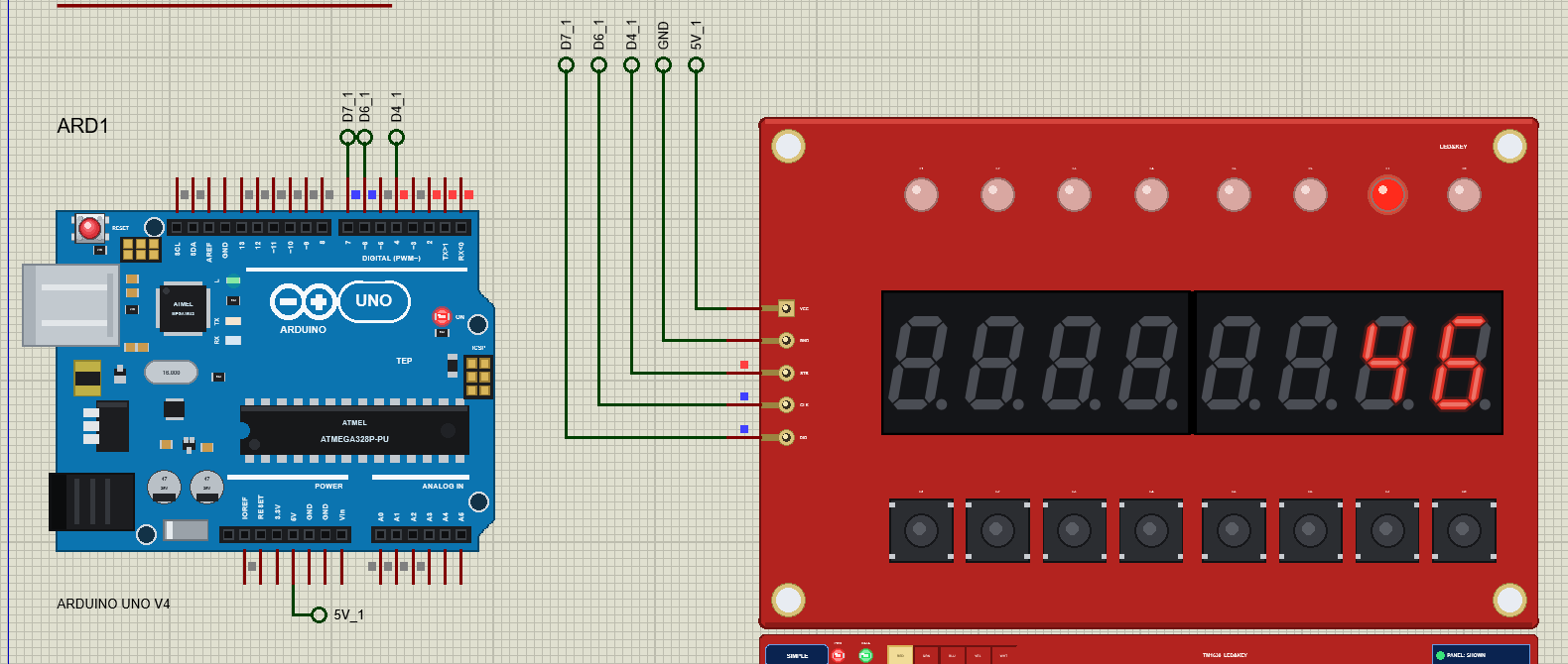
TM1638plus drives the pins itself, so any three pins work; the demo uses D4 for STB, D6 for CLK and D7 for DIO. VCC goes to 5V. The pull-up for the key data is on the module, so nothing else is needed.
The Arduino Code
The sketch uses the TM1638plus library 2.2.0 by Gavin Lyons:
#include <TM1638plus.h>One object for the module, with the STB, CLK and DIO pins; false tells the library that an UNO does not need extra delays:
TM1638plus tm(STB_PIN, CLK_PIN, DIO_PIN, false); // STB, CLK, DIO, false = not a high-frequency MCUD2 decides what the sketch starts with:
if (digitalRead(MODE_PIN) == LOW) { mode = KEYS; showText("PUSH 1-8"); }In the counter mode the loop counts every 100 ms after the two-second greeting and moves the running LED one place each time:
tm.setLED(runningLed, 0); runningLed = (runningLed + 1) % 8; tm.setLED(runningLed, 1);To change the sketch, export a new HEX and load it into the UNO; see How to get the HEX file from Arduino. New to Arduino? Start with our Arduino Tutorial for Beginners.
Serial Monitor Commands
| Command | What it does |
|---|---|
| HELP / STATUS | The command list / the mode, the display, the brightness, the buttons |
| COUNT / KEYS | The counter with a running LED / each button lights its LED and shows its number |
| TEXT <text> / NUMBER <n> | Eight characters (a dot lights a point) / a number right-aligned |
| BRIGHT <0-7> | The brightness |
| LEDS <hex> / LED <1-8> ON|OFF | All eight LEDs from one byte / one LED |
| BUTTONS | readButtons() now |
| SWAP | The classic mistake: STB and CLK swapped |
How to Run the Demo
- Press Run; move the monitor windows and TM2's pop-up aside.
- Click S1 - S8 on TM2's board: the button's LED lights and the digits show its number.
- In ARD1's monitor type STATUS, TEXT AbC.dEF.G, LEDS A5, NUMBER 12345678, BRIGHT 0 and BRIGHT 7.
- Try the mistake: SWAP, then COUNT; on TM2 open Tests and look at every tool.
TM1638 Proteus Simulation Results
The Built-in Serial Monitor in Its Simple Interface
Each Arduino UNO V4.0 carries our TEP Serial Monitor Advance, wired inside the board to D0 / D1. The screenshots show its Simple interface (Ctrl+Shift+U; Esc for the full view). Read all about it in TEP Serial Monitor Advance for Proteus.
ARD1: STATUS
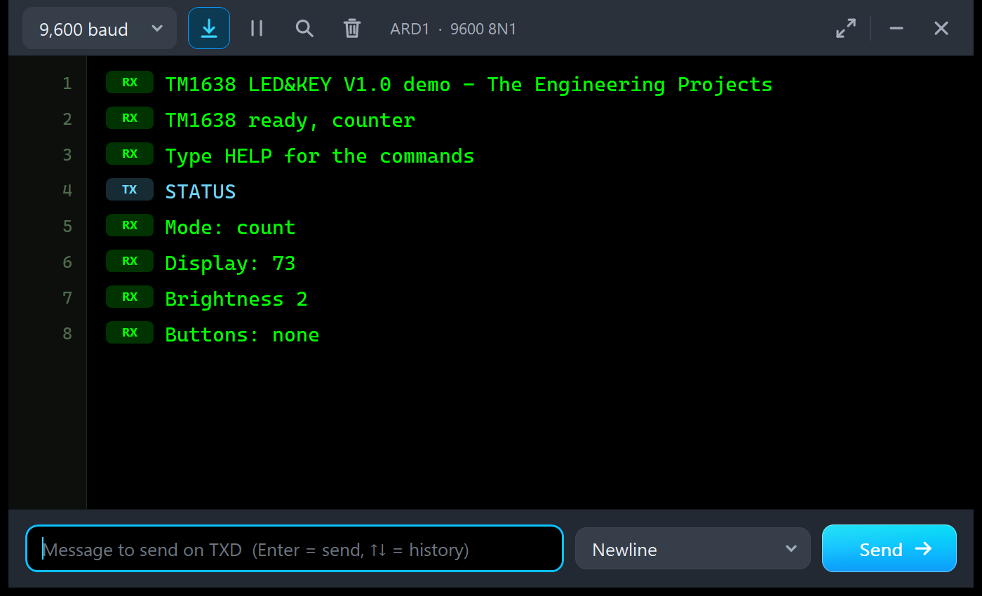
TM1638 LED&KEY V1.0 demo - The Engineering Projects
TM1638 ready, counter
Type HELP for the commands
STATUS
Mode: count
Display: 73
Brightness 2
Buttons: none
ARD1: LEDs, Brightness, Numbers and the Mistake
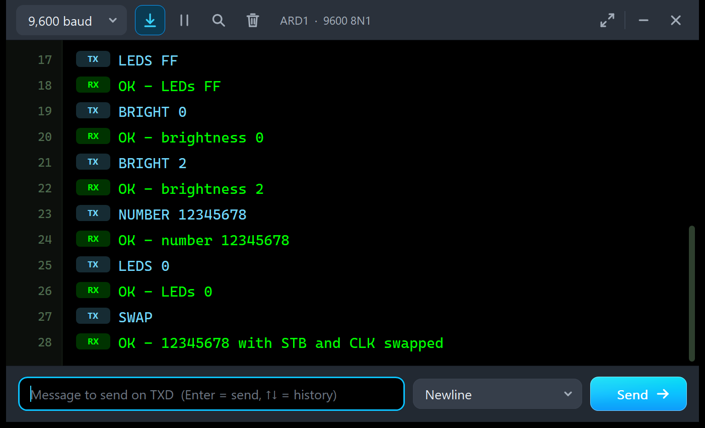
LEDS FF
OK - LEDs FF
BRIGHT 0
OK - brightness 0
BRIGHT 2
OK - brightness 2
NUMBER 12345678
OK - number 12345678
LEDS 0
OK - LEDs 0
SWAP
OK - 12345678 with STB and CLK swapped
ARD2: The Buttons
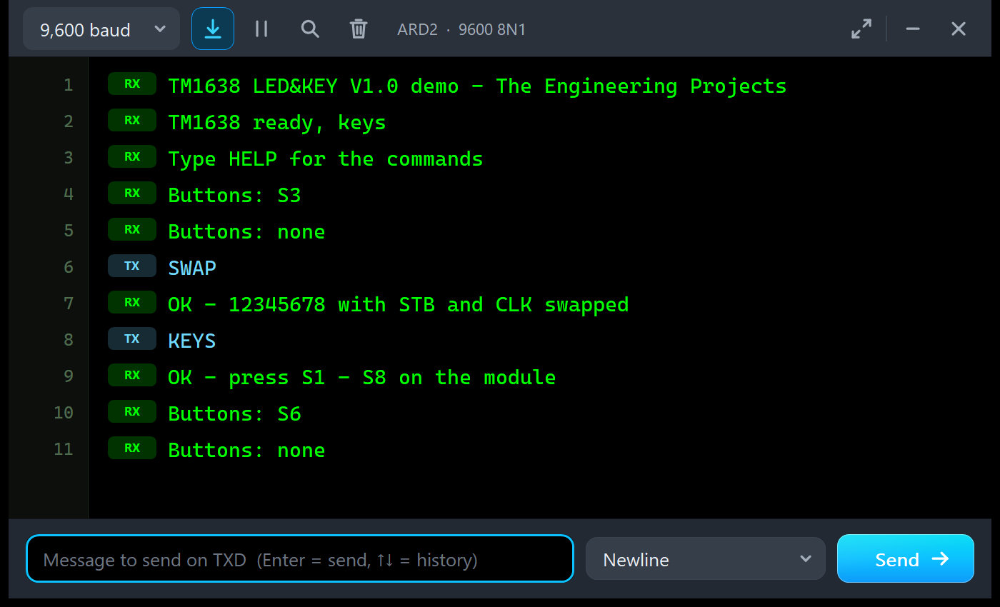
TM1638 LED&KEY V1.0 demo - The Engineering Projects
TM1638 ready, keys
Type HELP for the commands
Buttons: S3
Buttons: none
SWAP
OK - 12345678 with STB and CLK swapped
KEYS
OK - press S1 - S8 on the module
Buttons: S6
Buttons: none
The Simulation Log
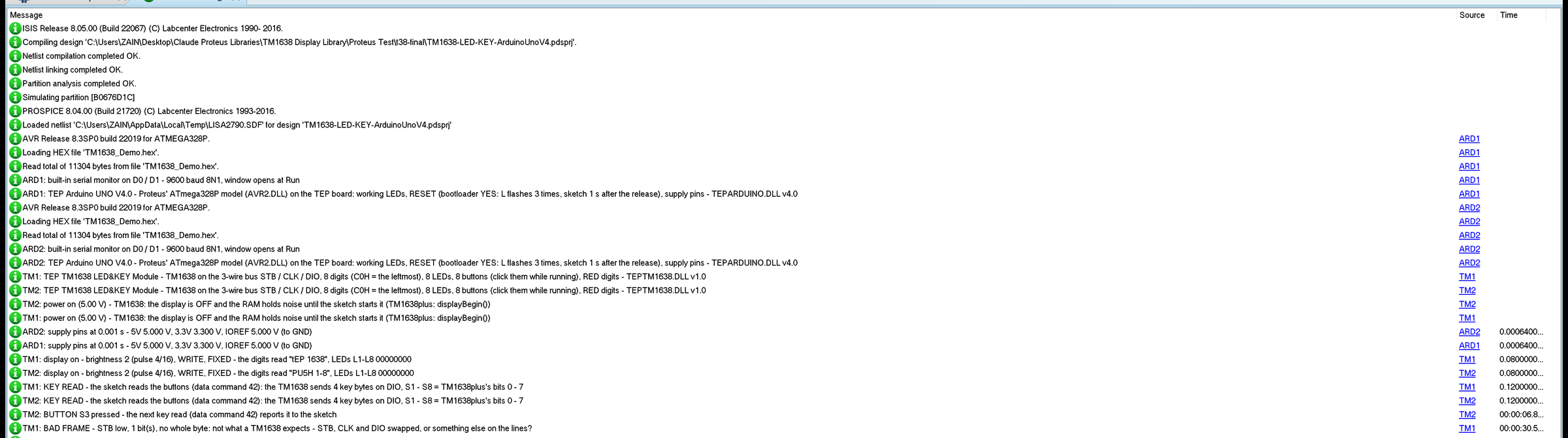
Each module writes a few lines to the simulation log: which board it is, the power-up state (display off), the first reading with the brightness and the LEDs, the first key read, the first button press and one line the first time a classic mistake happens. Nothing repeats, so the log stays readable in a long run.
Troubleshooting
- Dark digits with the PWR LED off: no power - check VCC and GND.
- DARK - NOTHING ON THE BUS YET: check STB on D4, CLK on D6 and DIO on D7, and the pins in
TM1638plus tm(STB, CLK, DIO). - DARK - DISPLAY OFF: CALL displayBegin(): the sketch never switched the display on.
- BAD FRAMES - STB / CLK / DIO SWAPPED?: swap the wires or the pins in the sketch.
- A button does nothing: the sketch must call
readButtons(); the Keys tool shows whether it does and what it got. - The wrong LED lights:
setLED()counts from 0, so L1 is position 0. - No part or no monitor: TEPTM1638.DLL or TEPARDUINO.DLL is missing from MODELS and the project folder; a closed monitor opens again with a click on the UNO's USB port.
Things to Know Before Using a Real TM1638 Module
- displayBegin(): call it once in setup(), or the display stays dark with random RAM.
- DIO works both ways: TM1638plus makes the Arduino pin an input while the TM1638 sends the key bytes. Do not drive DIO from anything else.
- Power: all segments and LEDs at full brightness draw about 160 mA, fine from an UNO; the module also runs at 3.3 V.
- Not I2C: STB frames every transfer and the bits go LSB first, so an I2C scanner finds nothing.
- Memory: the demo needs 11,304 bytes of flash and 771 bytes of RAM.
Limitations of the Simulation
- Not modelled: the key lines K1 and K2 (the LED&KEY board does not use them), the test mode's effect on the display, the multiplex itself (the segments show the average), the exact timing limits of the bus (only the clock rate is checked), the SEG9 / SEG10 outputs of other TM1638 boards, button bounce, and damage from a reversed supply.
- The strip, its LEDs and the panels are TEP additions.
- The model is our own, written from the TM1638 datasheet; TM1638 is a part of Titan Micro Electronics. This library is not made or endorsed by Titan Micro, the TM1638plus author or Labcenter.
- Licences: TM1638plus 2.2.0 (GPL-3.0) and the Arduino AVR core 1.8.6 with LGPL-licensed code are in the HEX file; the sketch is included, so you can share it under the GPL-3.0 and rebuild the HEX with modified libraries.
- Tested in Proteus 8.5 in October 2026 (the demo as shipped on two Arduino UNO V4.0 boards with their built-in monitors: the counter and the keys mode, buttons clicked on the board and on the pop-up, STATUS, TEXT, LEDS, NUMBER, BRIGHT and SWAP, the panel, the pop-up and the five tools; about 0.55 x real time with the pop-up and both monitors open). Proteus 7 is not supported.
Need fewer digits? Our TM1637 7-Segment Display Library for Proteus V1.0 simulates the 4-digit clock display with two wires, and our MAX7219 7-Segment Display Library for Proteus V1.0 drives the 8-digit MAX7219 board.
So, that was all about the TM1638 LED&KEY Library for Proteus V1.0. I hope the bus, the 16 RAM bytes and the key scan are clear now, so your front panel lights up and answers on the first real module you plug in. If you use the TM1638 LED&KEY Library for Proteus in a project, please share it in the comments or in our forum, and if you have any questions, ask in the comments and I will help you out. Till the next tutorial, take care and have fun!