Hello friends, I hope you all are doing great. Today, I am going to share the Electromagnetic Fire Door Holder with ESP32 | Proteus Simulation, the forty-third project of our IoT Projects series. If you have searched for a Proteus simulation of an electromagnet controlled by an ESP32, or of the magnetic door holders that keep fire doors open in hospitals, schools and offices, here is a complete one. An ESP32 holds a fire door open with a 12 V holding electromagnet and lets it go the moment the fire alarm panel calls, when someone presses the RELEASE button, or when the power fails. Then it checks that the door really closed, and it serves a live web dashboard on a laptop or a phone.
Fire doors stop smoke and flames from spreading along corridors and stairs, but only when they are shut, and a shut door in a busy corridor is a door that people wedge open with a chair. Magnetic door holders are the answer: the door stays open on a magnet during the day, and the fire alarm cuts the magnet's power so the door's closer pulls it shut. In this tutorial, we will go through the circuit, see how a holding electromagnet works and why it lets go some milliseconds after its power is cut, drive it from an ESP32 through an L9110S, learn why the fire panel's contact is normally closed and why the magnet is on only while it may hold, add a closing check that catches a jammed door, walk through the Arduino sketch, and then run the simulation: a release from the button, a fire alarm with a door that does not close in time, and a release from the phone. At the end, you can download the project with the sketch and every library file.
NOTICE: Our team has put a lot of effort into this project: the circuit, the code and every part in the simulation are our own work, and you get them all free. Your feedback is the fuel that keeps us going, so please tell us what you think in the comments below. And if our free projects help you, you can buy us a coffee. So, let's get started with the electromagnetic fire door holder with ESP32 in Proteus simulation:
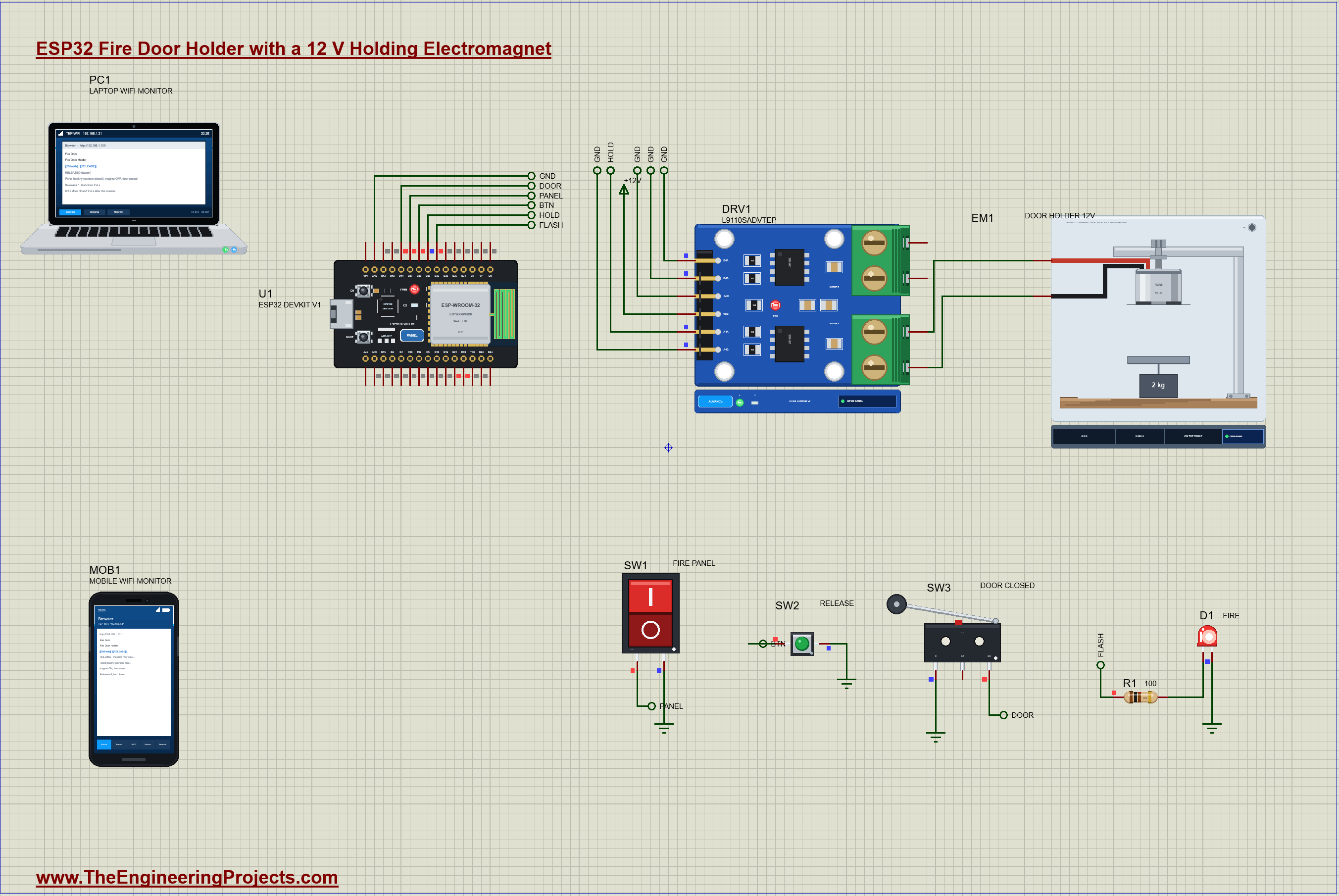
What Does This Fire Door Holder Do?
- Holds the door open: a 12 V holding electromagnet keeps the door's steel plate, and so the door, against it.
- Releases it on the fire alarm: the fire panel's contact opening cuts the magnet, and the door closes.
- Fail-safe: a cut wire to the panel or a power failure releases the door too; the magnet is on only while it may hold.
- RELEASE button and dashboard: a person at the door, or anyone on the dashboard, can free the door for 5 s.
- Checks the door closed: a door contact must see it shut within 10 s of every release, or DOOR FAULT.
- A flashing LED and a dashboard: the alarm shown at the door, and the state, the releases and the events on a laptop or a phone.
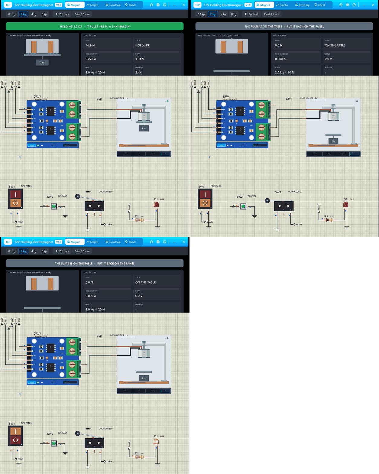
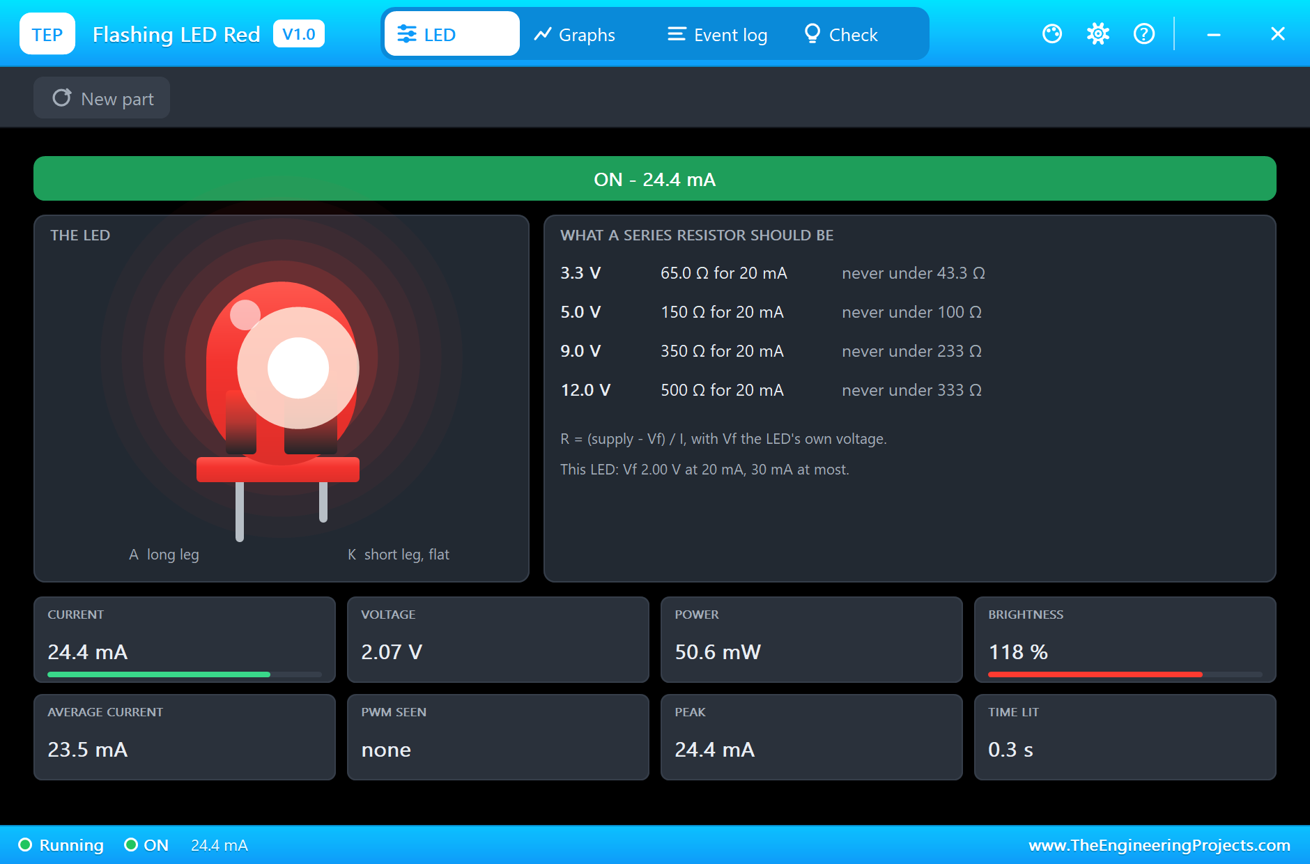
It is a great project for learning how electromagnets hold and release, how to design inputs that fail safe, how to debounce switches, and how to supervise a mechanical action with a sensor. In the simulation, the electromagnet's pop-up shows its pull, the coil current and the plate falling onto the table, the switches' pop-ups show their contacts, and the flashing LED's pop-up shows it lit during the alarm.
Components Used in the Proteus Simulation
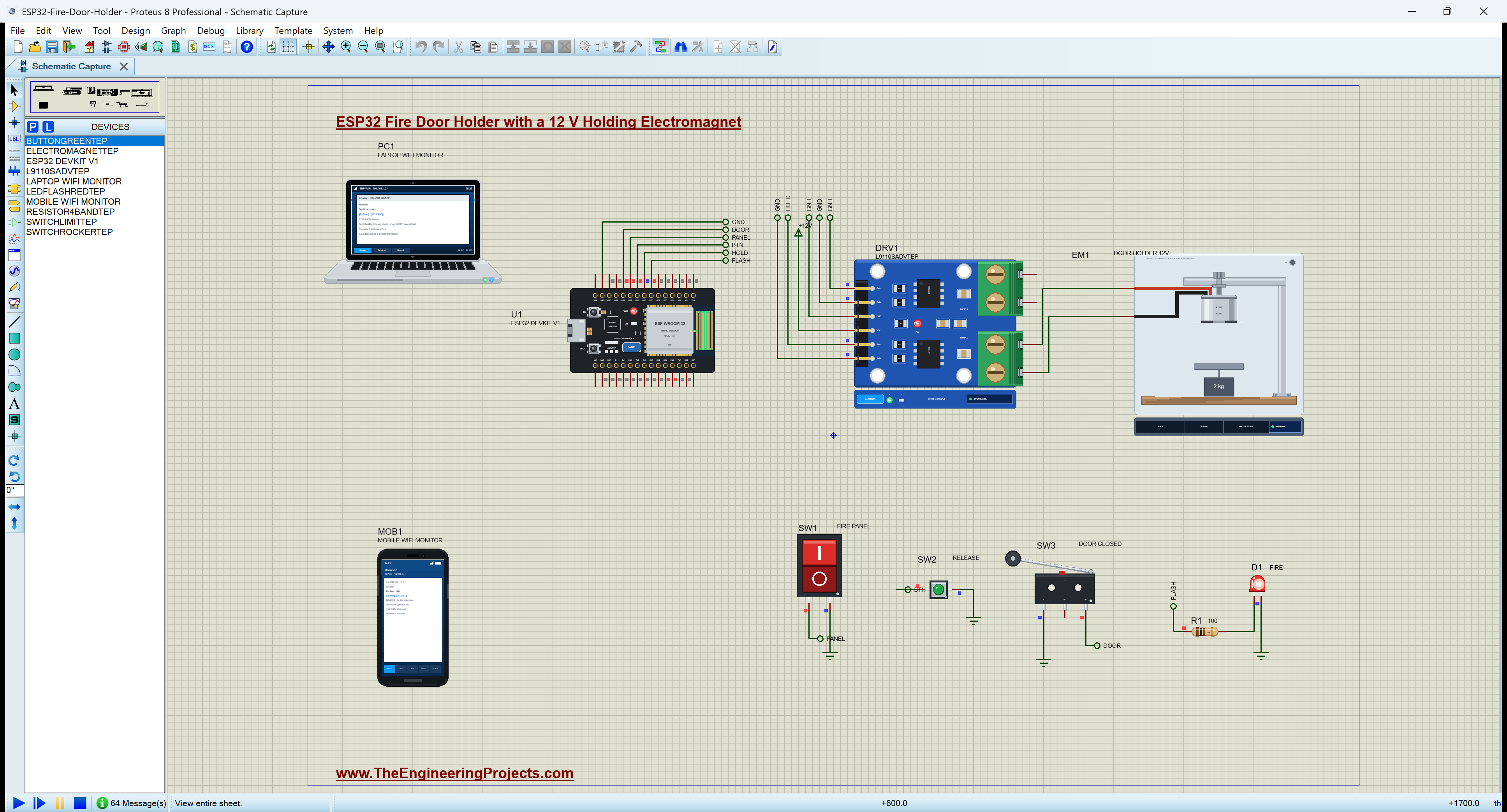
All the parts come from our Proteus libraries, each with its own tutorial. The project zip at the end includes every LIB and DLL file.
| Part | Proteus device | Library post | Connection |
|---|---|---|---|
| ESP32 DevKit V1 | ESP32 DEVKIT V1 | ESP32 DevKit V1 Library for Proteus | U1, TEP-WiFi 192.168.1.101 |
| 12 V holding electromagnet | ELECTROMAGNETTEP | 12V Holding Electromagnet Library for Proteus | EM1, on the L9110S's motor A |
| L9110S motor driver | L9110SADVTEP | L9110S Motor Driver Library for Proteus | DRV1, A-IA from D25 |
| Rocker switch | SWITCHROCKERTEP | Rocker Switch Library | SW1, the fire panel's contact, D27 |
| Green push button | BUTTONGREENTEP | Push Button Library | SW2, RELEASE, D26 |
| Micro limit switch | SWITCHLIMITTEP | Micro Limit Switch Library | SW3, the door contact, D14 |
| Red flashing LED | LEDFLASHREDTEP | Flashing LED Library | D1, FIRE, D33 |
| Resistor 100 | RESISTOR4BANDTEP | Resistor Library | R1, the LED's |
| Laptop WiFi Monitor | LAPTOP WIFI MONITOR | Laptop WiFi Monitor | PC1 |
| Mobile WiFi Monitor | MOBILE WIFI MONITOR | Mobile WiFi Monitor | MOB1 |
The rocker switch stands in for the fire alarm panel's output contact, which in a real building is a relay inside the panel; the micro limit switch is the door contact a door holder system uses to know the door is shut. The 12 V supply is a Proteus power terminal on the driver's VCC.
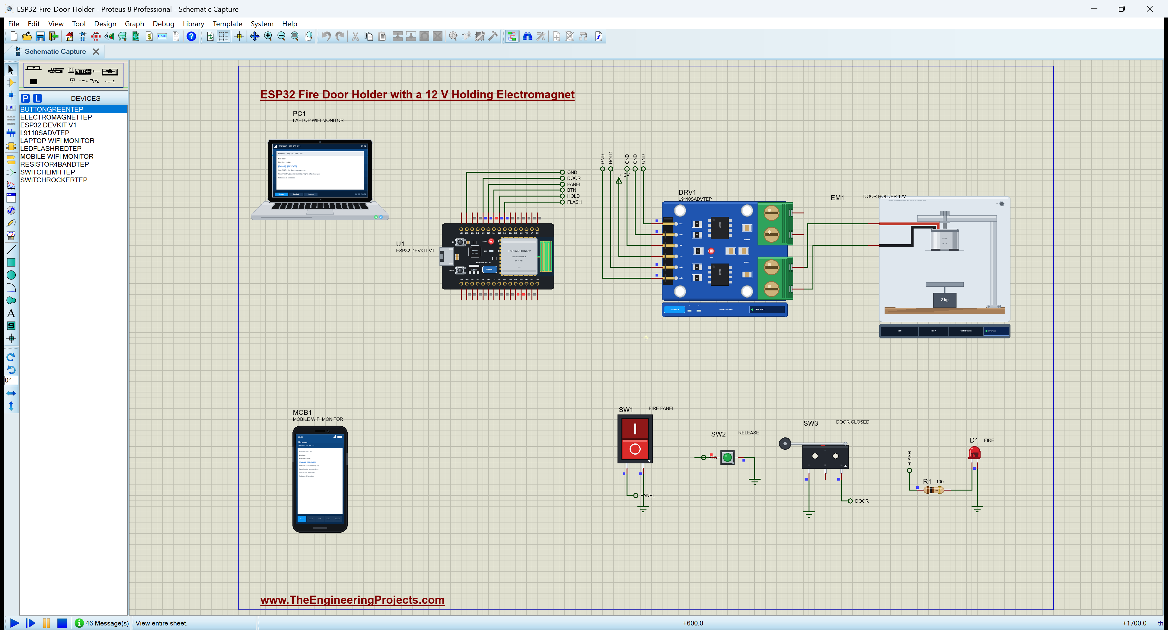
Proteus Simulation of the Fire Door Holder: the Circuit
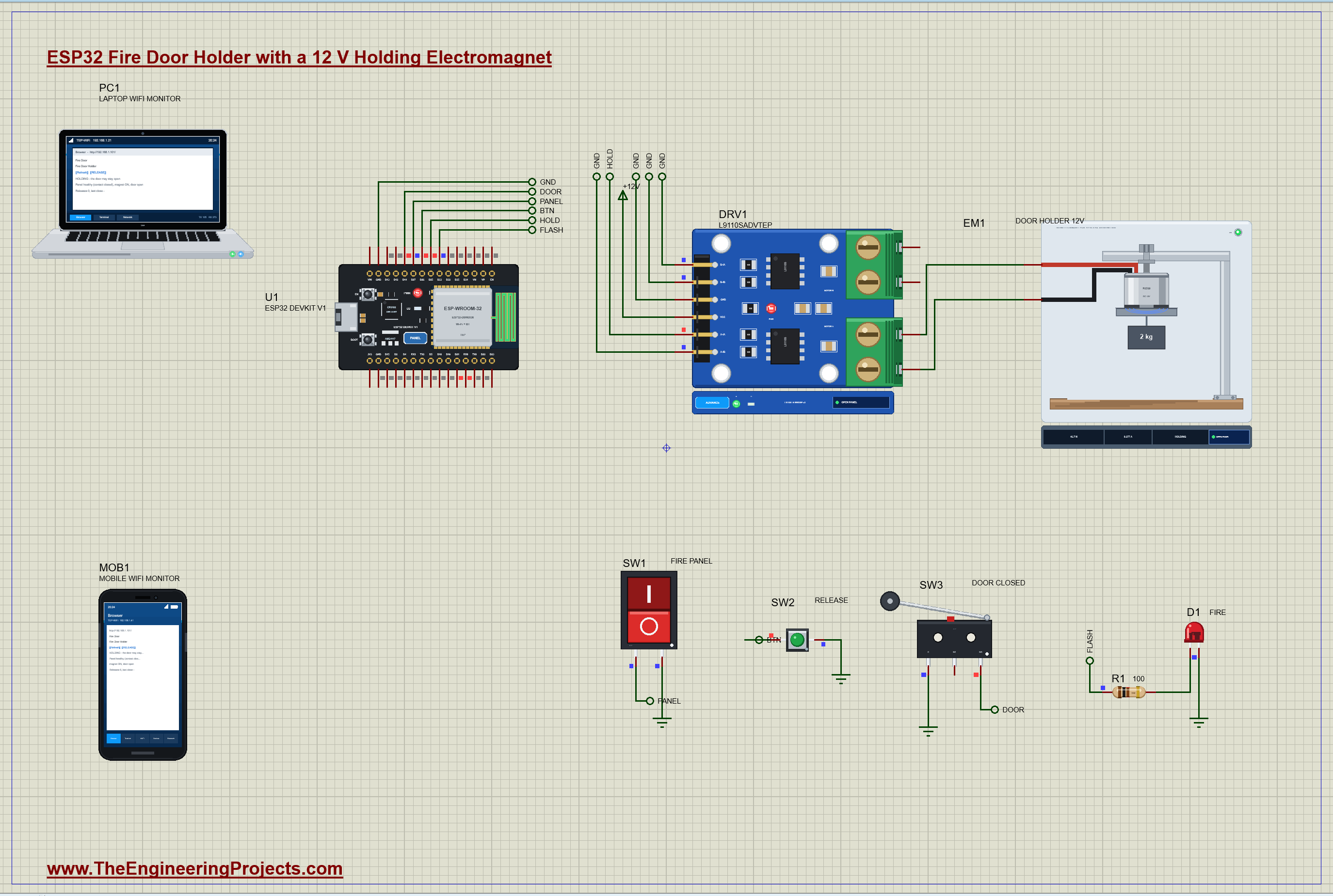
| Part | Pins | ESP32 / other |
|---|---|---|
| DRV1 L9110S | A-IA / A-IB, B-IA / B-IB | D25 (HOLD) / GND, GND / GND |
| DRV1 L9110S | VCC / GND / A-OA, A-OB | +12 V / GND / the magnet's + and - |
| SW1 rocker (the panel) | 1 / 2 | D27 (PANEL, pull-up) / GND |
| SW2 button | 1 / 2 | D26 (BTN, pull-up) / GND |
| SW3 limit switch | C / NO | GND / D14 (DOOR, pull-up) |
| D1 flashing LED | A / K | D33 (FLASH) through R1 100 ohm / GND |
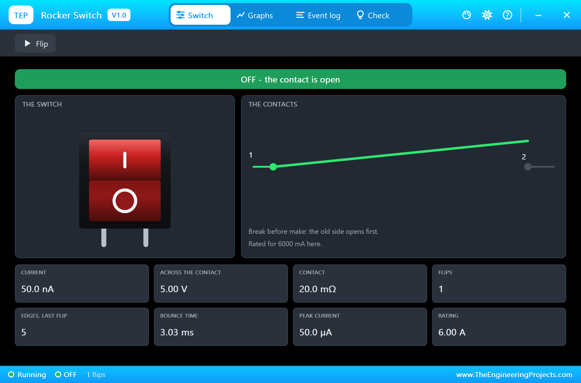
All three switches are wired the same way: between an ESP32 pin and ground, with the pin's internal pull-up, so a closed switch reads LOW. The panel's contact starts closed (the rocker's STATE property is 1), the button is open until pressed, and the door contact is pressed only when the door is shut. The magnet hangs on motor A of the L9110S: with A-IA HIGH and A-IB LOW the driver puts the 12 V supply across the coil; with A-IA LOW both outputs are low and the coil is off.
How the Fire Door Holder Works
A Holding Electromagnet
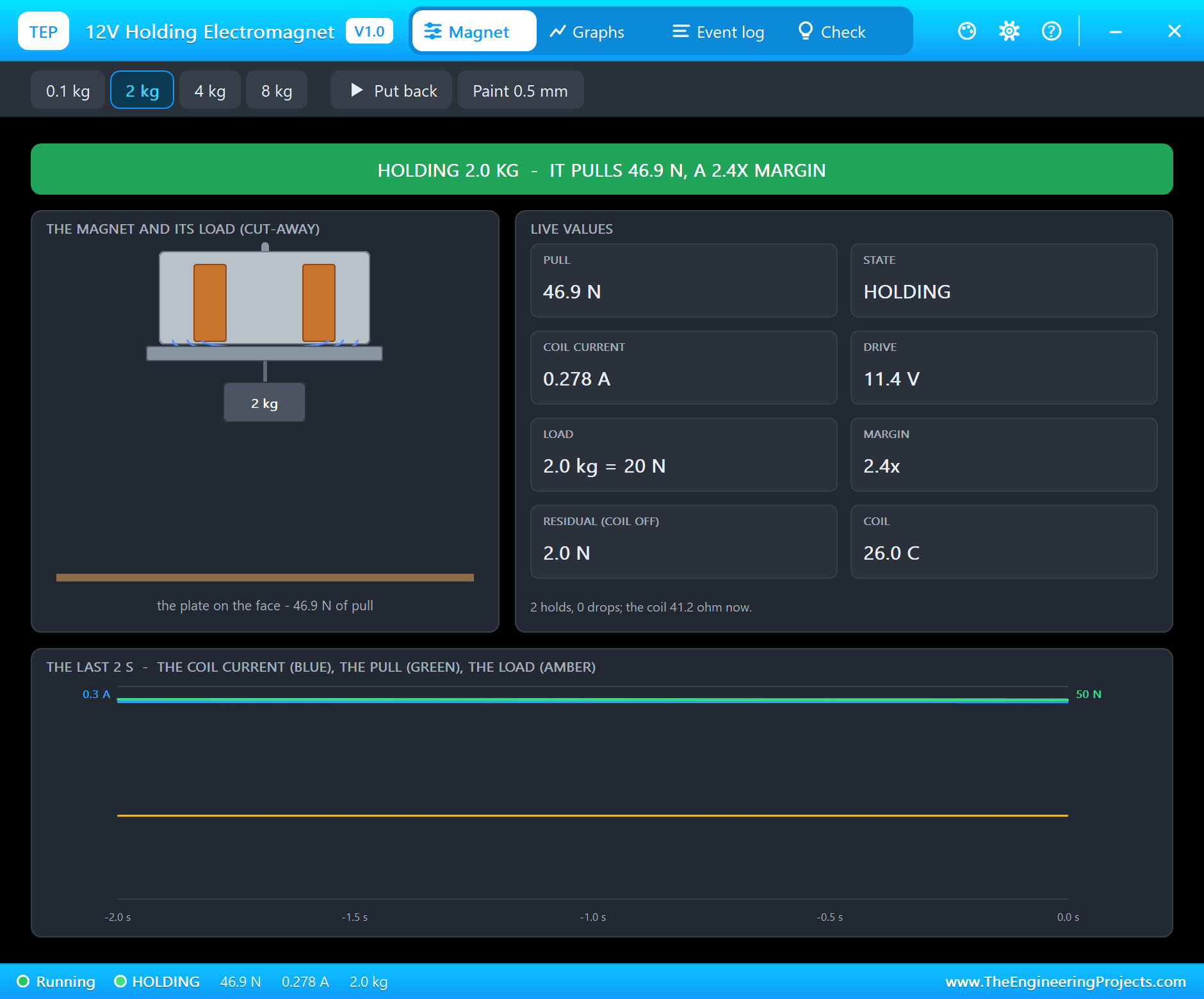
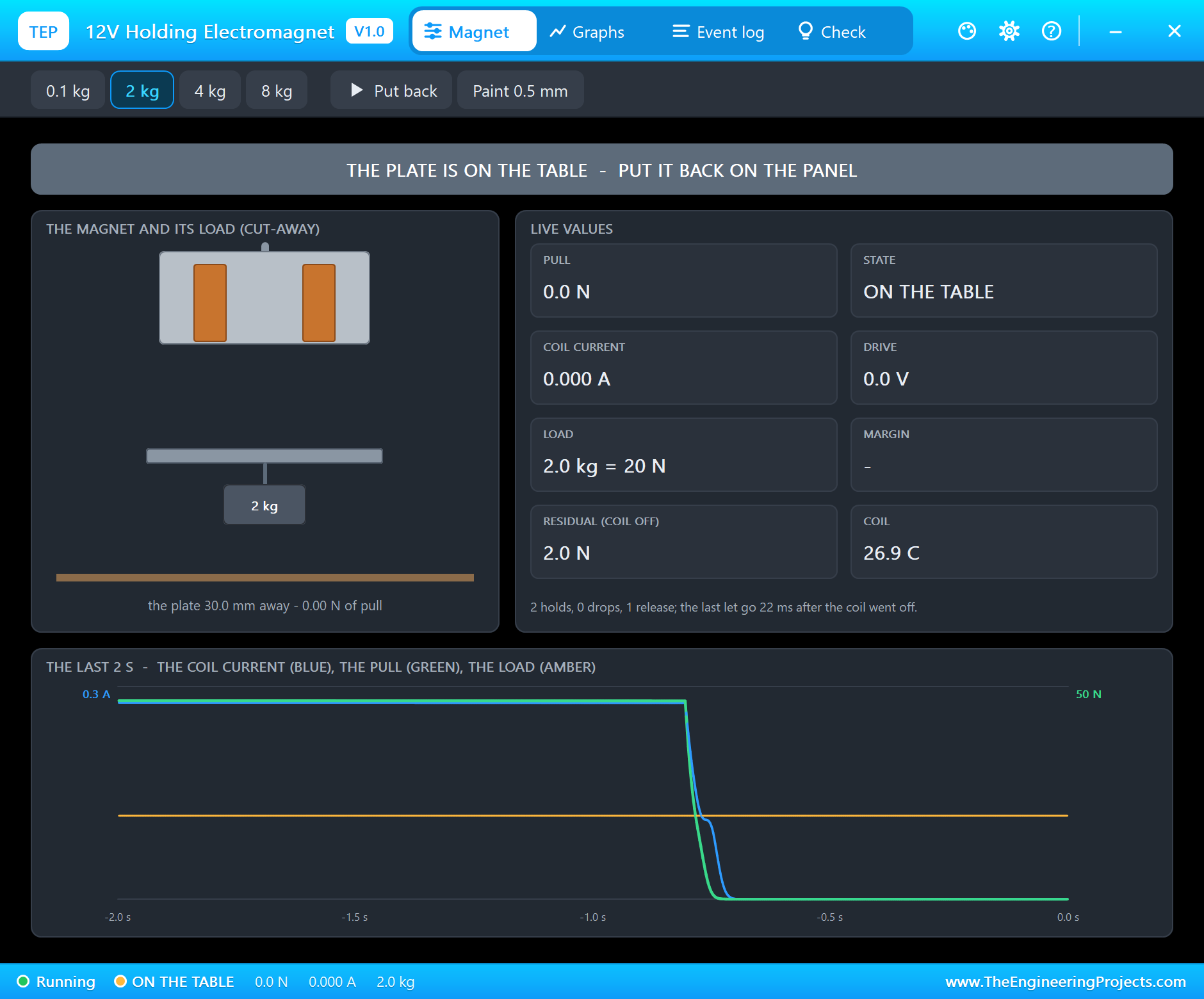
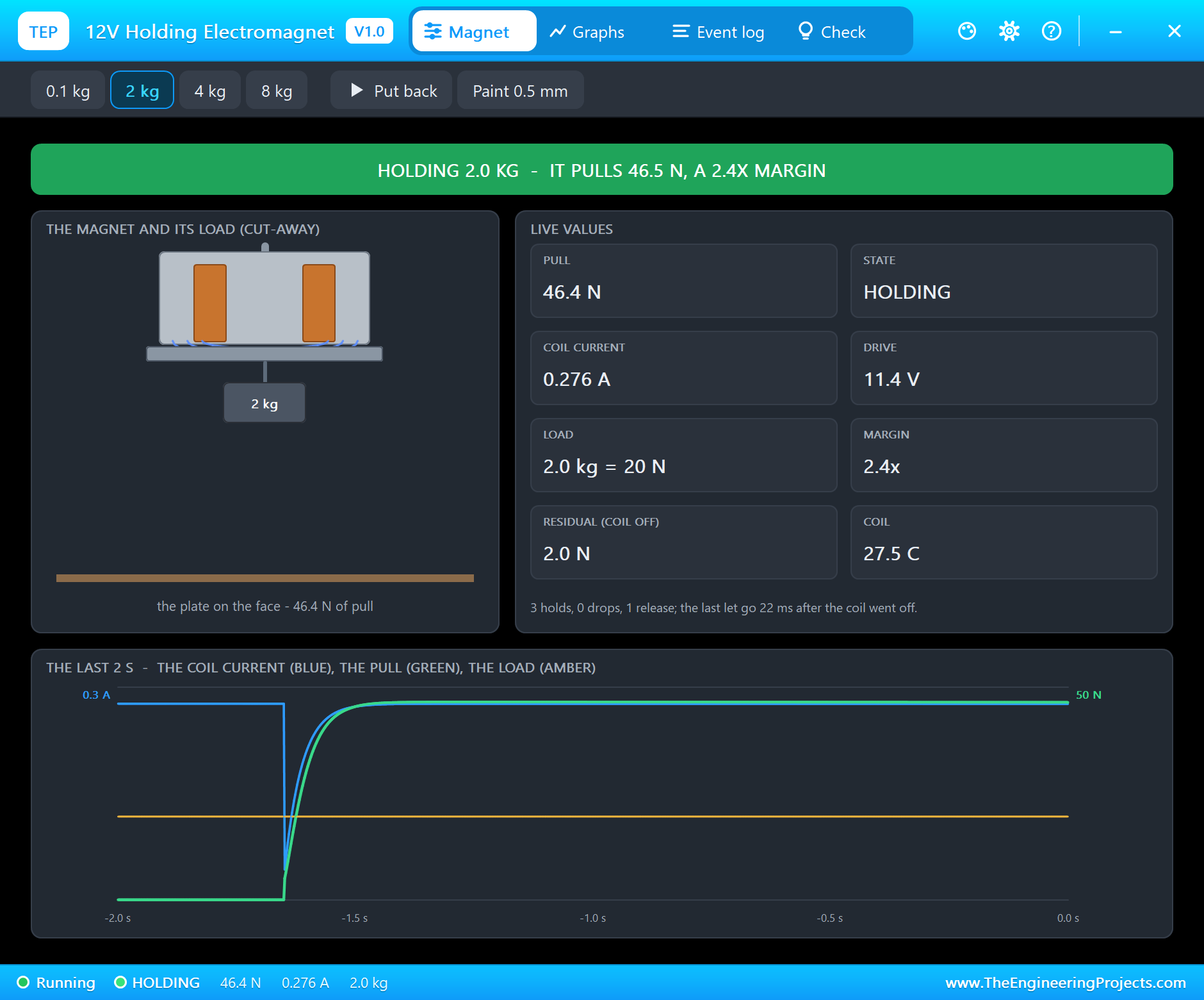
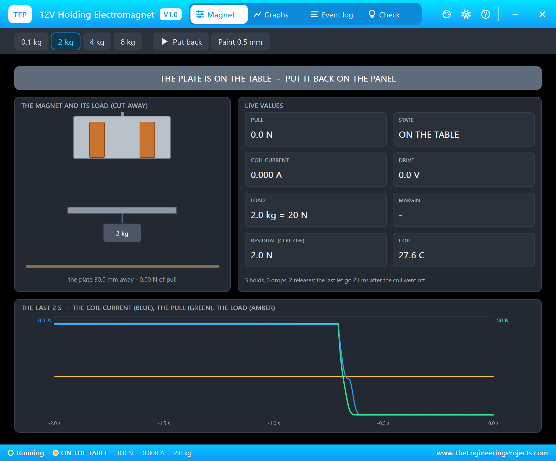
A holding electromagnet is a coil inside a steel pot. With current in the coil, the pot's face becomes a magnet that holds a steel plate flat against it; the plate closes the magnetic circuit, so the pull is strong only when the plate actually touches the face. Our magnet's coil is 41 ohm, so on 12 V it takes about 0.29 A, 3.5 W. Its inductance is 1.58 H with the plate on and only 0.21 H without it, because the plate closes the iron path. In the simulation it pulls 46.9 N on the face, while the 2 kg load, standing for the door closer's pull, weighs 19.6 N: a margin of 2.4 times. Worked example: the pull grows with the square of the current, so the magnet holds the door down to about 0.29 A / sqrt(2.4), roughly 0.19 A, and then lets go.
That square law also explains why the plate lets go a little after the power is cut. A coil's current cannot stop at once: it dies away with the time constant L / R, here 1.58 H / 41 ohm, about 38 ms, through the driver's diodes. The plate falls when the current has dropped far enough that the pull no longer beats the load, which in the simulation is 21 to 22 ms after the coil went off. Steel also keeps a little magnetism of its own, about 2 N in our magnet, enough to hold a very light plate with the coil off. That is why real door holders pair the magnet with a door closer strong enough, and often a thin non-magnetic layer on the plate, so the door always lets go.
Driving the Magnet with an L9110S
An ESP32 pin gives a few milliamps; the coil needs 290. The L9110S is a small H-bridge, made for motors, that switches up to 800 mA from a 2.5 to 12 V supply and has the diodes a coil needs built in. One input HIGH and the other LOW puts the supply across the load; both LOW turns it off and lets the coil's current die away through the diodes. On 12 V it loses about half a volt, so the coil sees 11.4 V and takes 0.278 A. Its second channel, motor B, has both inputs grounded and is unused here.
Fail-Safe Inputs and a Fail-Safe Output
A safety system has to decide what happens when something breaks, and the answer here is always the same: the door closes. The fire panel's contact is normally closed, so it is closed while all is well and opens for a fire; a cut wire or a loose terminal looks exactly like an alarm and releases the door. The output works the same way: the magnet is energised only while it may hold, so a power cut, a crashed ESP32 or a burnt driver also releases the door. A design the other way round, with a contact that closes for a fire or a magnet that must be powered to release, would fail with the door stuck open, the worst way a fire door can fail. In Europe, electrically powered hold-open devices like this are covered by the standard EN 1155.
Debouncing and the Closing Check
Mechanical contacts bounce: for a few milliseconds after they move, they open and close many times. The sketch accepts a new level on any input only after it has held for 100 ms, which hides the bounce and also rejects electrical noise on a long cable to the panel. After every release the sketch starts a 10 s timer and waits for the door contact to report the door shut. If the door is wedged, held by a person, blocked by a trolley or its closer has failed, the timer runs out and the dashboard shows DOOR FAULT, the one fault a fire door must never hide. When the door does close, the event says how long it took, which over months shows a closer getting weak.
The Arduino Code Explained
The whole sketch is included in the download. It needs only the ESP32 core: WiFi and WebServer for the dashboard. At the top are the two times that matter:
const unsigned long BUTTON_RELEASE_MS = 5000;                       // the RELEASE button frees the door for 5 s
const unsigned long CLOSE_LIMIT_MS = 10000;                         // after a release the door must be closed within 10 s
Holding the Door from the Start
A door holder must hold as soon as it has power, so the magnet comes on in setup(), before the WiFi, if the panel is healthy:
  if (digitalRead(PANEL) == LOW) {                                   // the panel healthy: hold the door at once, before the WiFi
    magnetOn = true; digitalWrite(MAGNET, HIGH);
The Inputs
Each input is a small structure that reports a change only after the new level has held for DEBOUNCE_MS. The panel's contact open, or its wire cut, is a fire:
else if (now - since >= DEBOUNCE_MS) { level = raw; since = now; return true; } alarm = panelIn.level == HIGH; // the contact OPEN (or its wire cut): FIRE releaseUntil = millis() + BUTTON_RELEASE_MS;The Magnet and the Closing Check
One line decides the magnet: on only with no alarm and no release running. When it goes off, the release is counted and the closing check starts, unless the door is already shut:
bool want = !alarm && (long)(now - releaseUntil) >= 0; digitalWrite(MAGNET, magnetOn ? HIGH : LOW); releases++; releasedAt = now; watch = !doorClosed; fault = false; if (watch && now - releasedAt > CLOSE_LIMIT_MS) { lastClose = (now - releasedAt) / 1000.0; digitalWrite(ALARM_LED, alarm ? HIGH : LOW);The flashing LED needs no code to flash: it has its own oscillator chip inside and flashes twice a second whenever it has power, so the ESP32 only switches it on and off. The pages are / (the dashboard), /release (the same as the button) and /data (JSON). The dashboard puts its links first and stays short, because the WiFi Monitors show one screen of a page.
How to Run the Proteus Simulation
- Download the project zip below and install the library files (the steps are under the download button).
- Open ESP32-Fire-Door-Holder.pdsprj from the Proteus Simulation folder. Keep the HEX and the DLL files next to it.
- Press Play. The magnet comes on and holds its plate: the door is held open.
- Press the RELEASE button (SW2): the plate drops; click the door contact (SW3) to close the door. Use the magnet's Put back to hold the door again.
- Click the rocker (SW1) to open the fire panel's contact: FIRE. Open the Laptop or the Mobile WiFi Monitor and press Go for the dashboard.
Simulation Results: the Fire Door Holder in Proteus
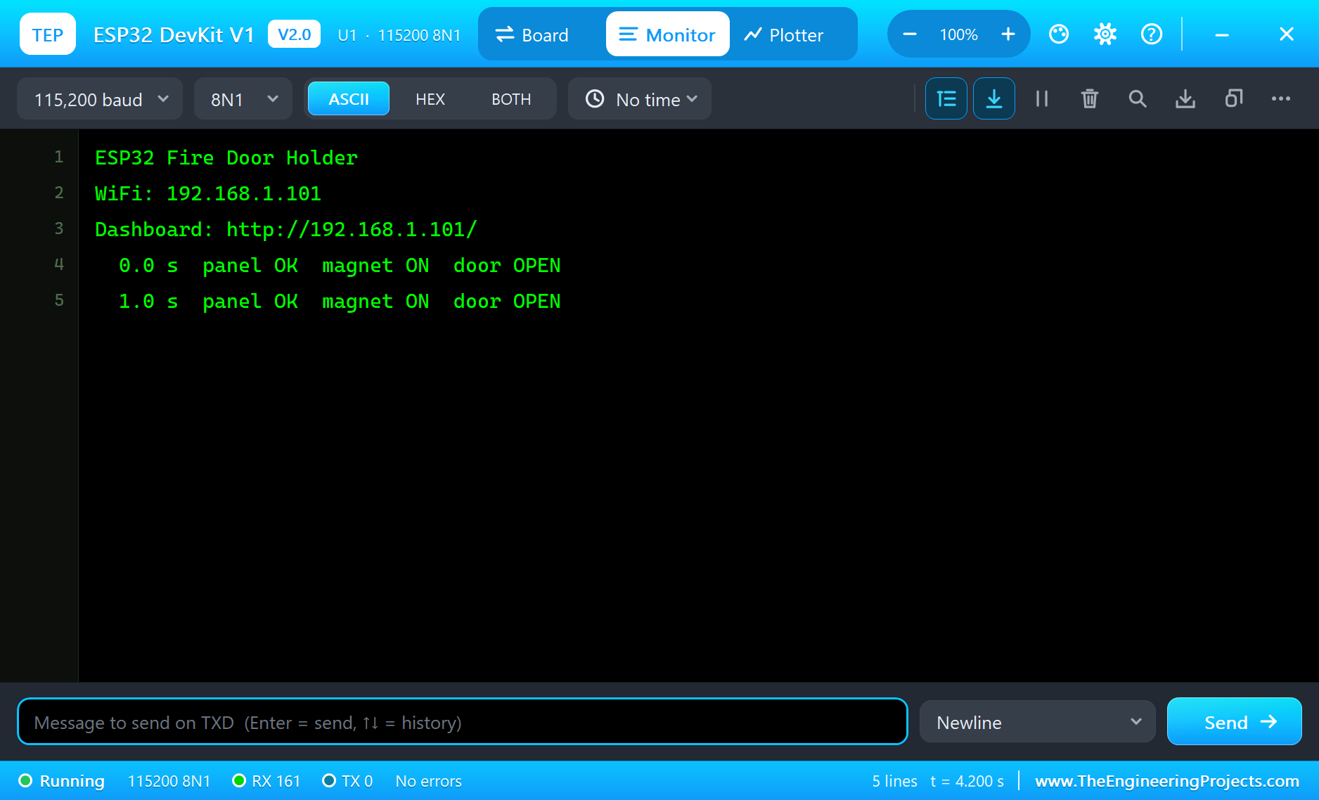
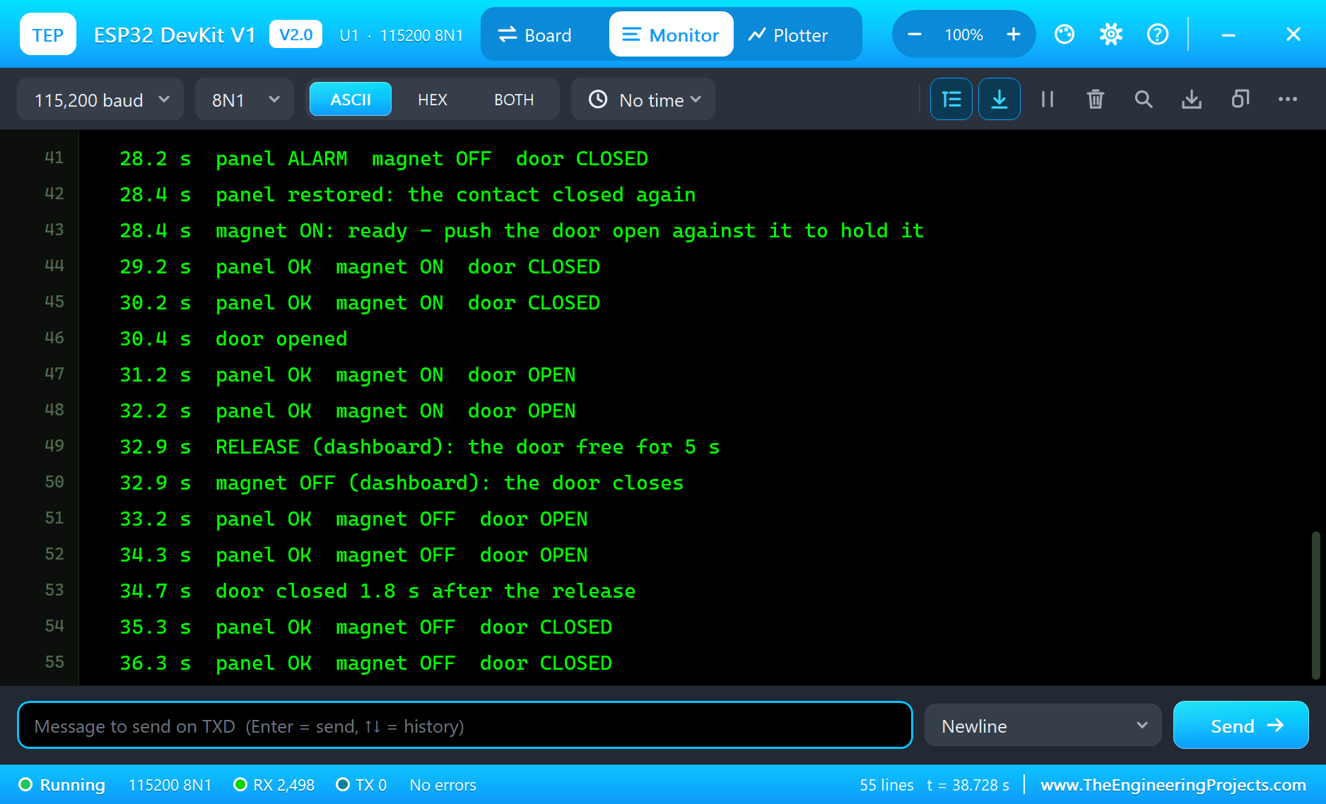
Here is the run that made the screenshots of this tutorial, 38.8 seconds of simulation. The times below are the sketch's own, as it printed them on its serial monitor; its clock starts once the WiFi is up, 2.3 s into the simulation. The magnet's numbers come from its own pop-up and log.
Power-up: the Door Held
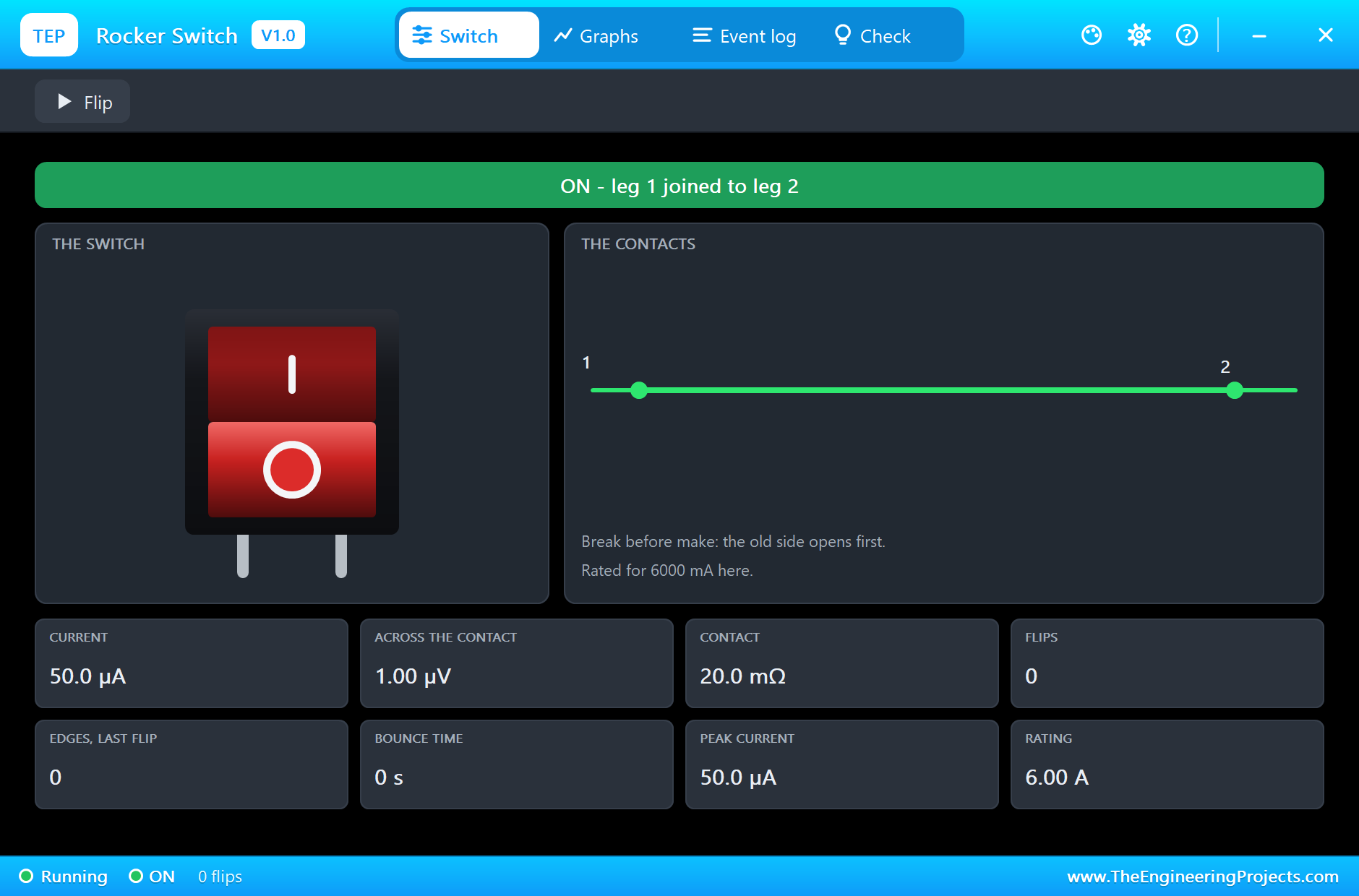
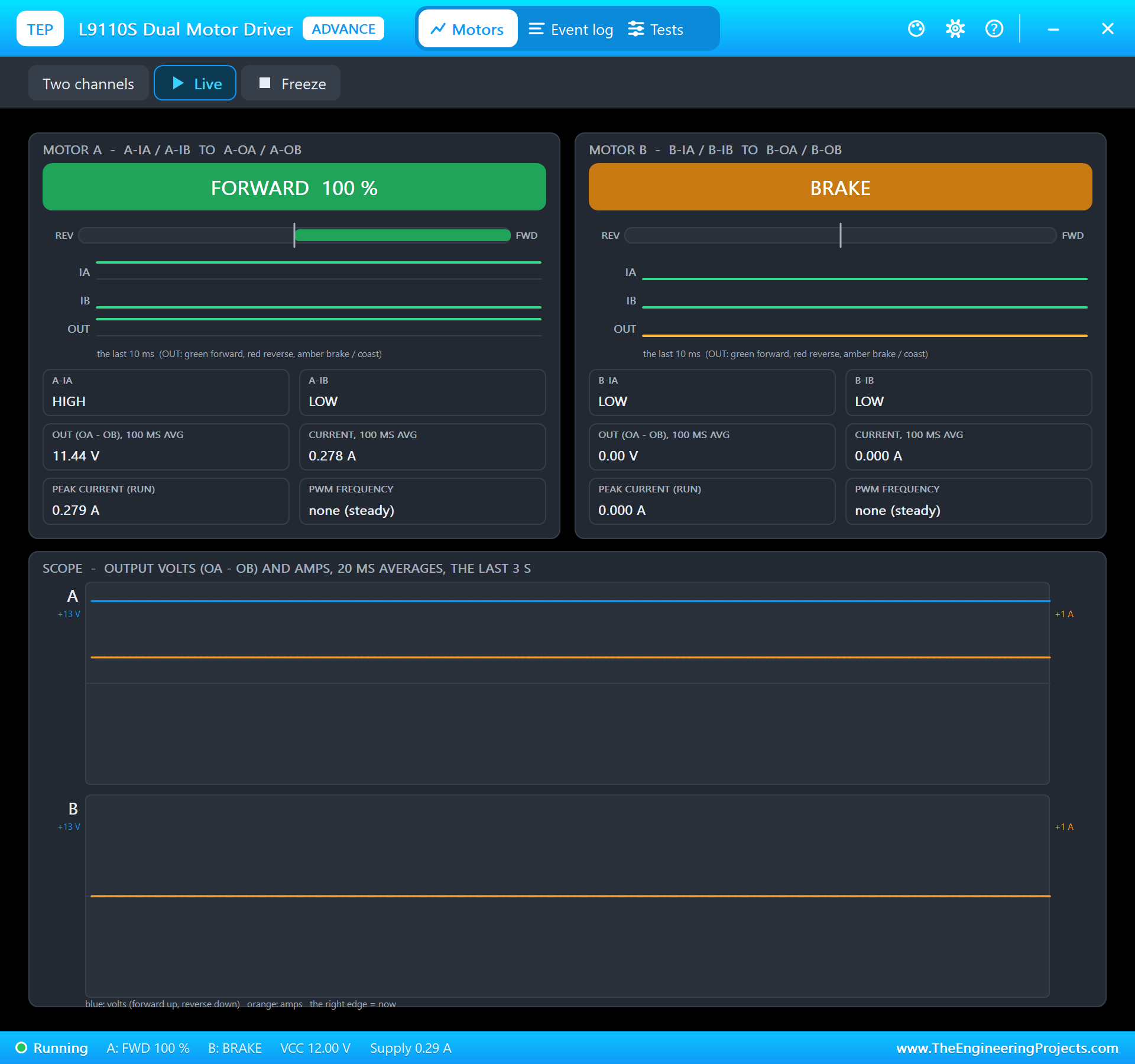
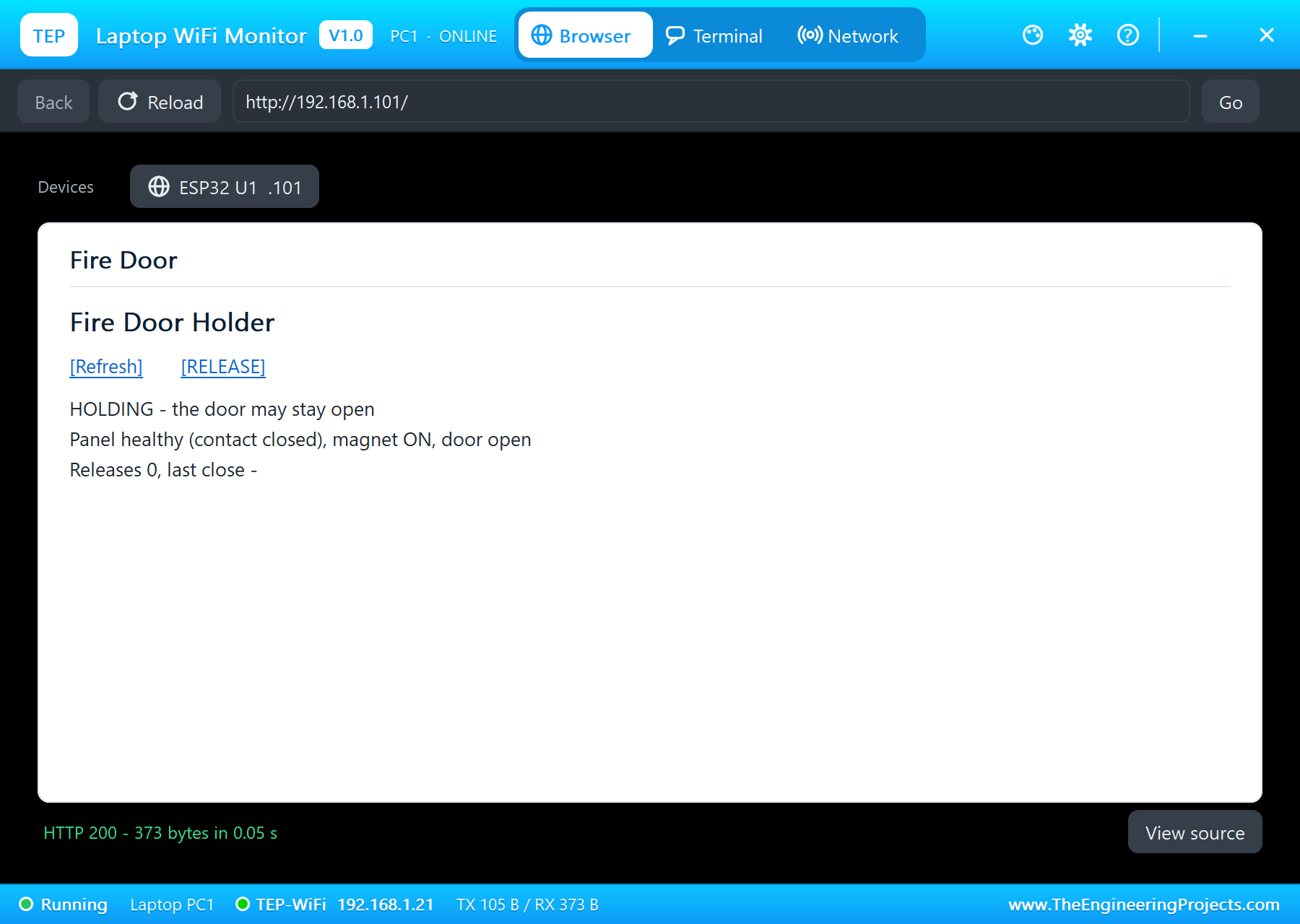
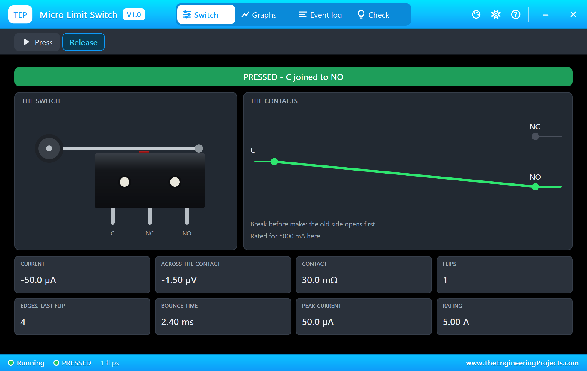
The magnet comes on in setup(), and half a second into the simulation it holds its 2 kg plate: it pulls 46.9 N on the face, a 2.4 times margin, with 0.278 A in the coil and 11.4 V across it. The L9110S's pop-up shows motor A forward at 100 % and motor B unused, both its inputs low; the rocker's pop-up shows the panel's contact closed, leg 1 joined to leg 2. The serial monitor prints "panel OK magnet ON door OPEN" every second, and the dashboard says HOLDING.
The RELEASE Button
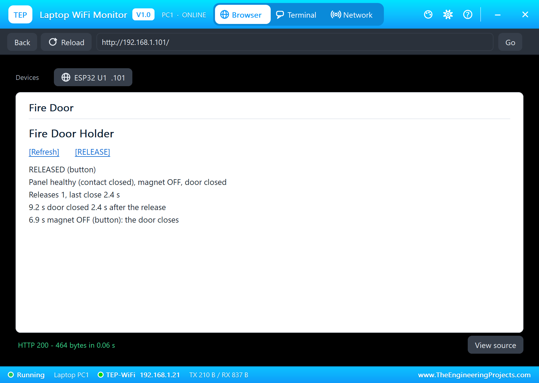
At 6.9 s the green RELEASE button is pressed: "RELEASE (button): the door free for 5 s" and "magnet OFF (button)". The magnet's log reports the plate letting go 22 ms after the coil went off, while its current died away, and the plate falls onto the table. At 9.2 s the door reaches its contact: "door closed 2.4 s after the release", well inside the 10 s limit. At 11.9 s the 5 s are over and the magnet comes back on, "ready - push the door open against it to hold it". At 12.7 s the door is opened and pushed against the magnet, and it holds again.
Fire, and a Door That Does Not Close
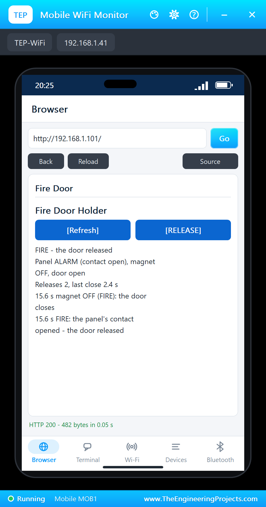
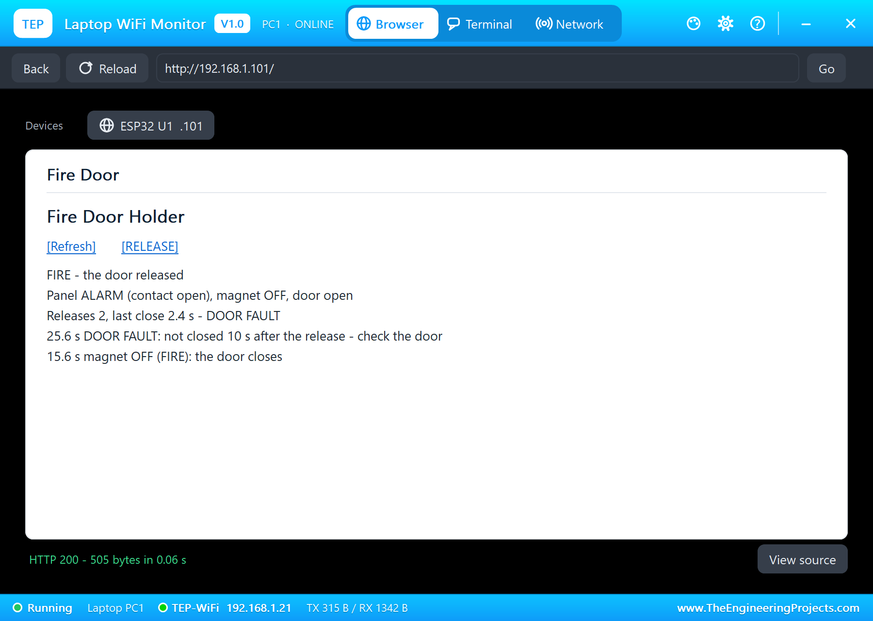
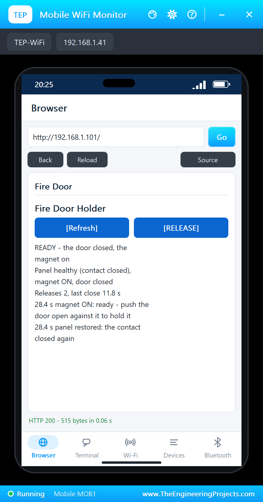
At 15.6 s the fire panel's contact opens: "FIRE: the panel's contact opened - the door released". The magnet goes off, the plate lets go 21 ms later, and the red LED starts flashing. This time the door is left open, as if a trolley were in the way, and at 25.6 s, ten seconds after the release, the sketch says so: "DOOR FAULT: not closed 10 s after the release - check the door", on the serial monitor and on the dashboard. At 27.4 s the door finally closes, and the event records it honestly: "door closed 11.8 s after the release (late)". At 28.4 s the panel's contact closes again, "panel restored", and the magnet comes back on, ready; the door stays shut until someone opens it.
RELEASE from the Dashboard
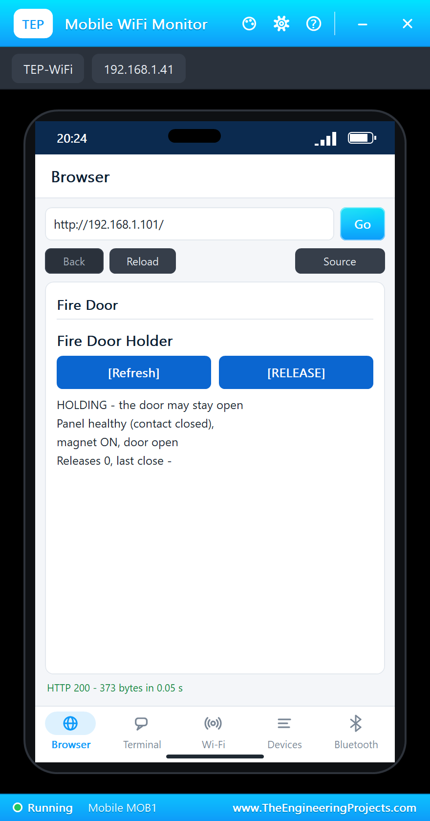
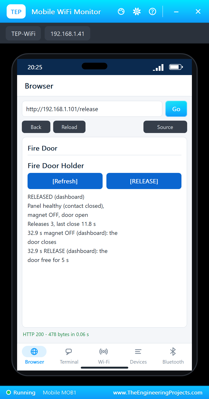
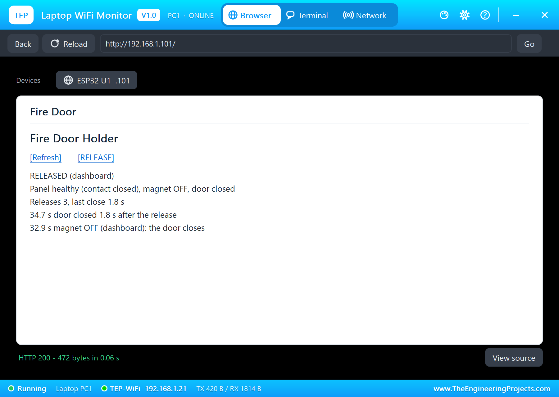
At 30.4 s the door is opened and held again. At 32.9 s RELEASE on the phone's dashboard: "RELEASE (dashboard): the door free for 5 s", the plate lets go 21 ms after the coil, and at 34.7 s "door closed 1.8 s after the release". By the end, three releases, every one counted with its closing time.
The Numbers of the Run
| What | Result |
|---|---|
| Holding | 46.9 N for a 19.6 N load (2.4x), 0.278 A, 11.4 V |
| Release time | the plate let go 21 - 22 ms after the coil went off |
| The button | the door closed 2.4 s after the release |
| Fire | DOOR FAULT at 10 s; the door closed late, at 11.8 s |
| The dashboard | the door closed 1.8 s after the release |
| Simulation | 38.8 s of simulation, 3 releases |
Download the Project Files
Click the button below to download ESP32-Fire-Door-Holder-Electromagnet-Proteus-Simulation-v1.0.zip (about 4.8 MB, without the source code of the models):
Electromagnetic Fire Door Holder with ESP32 in Proteus Simulation V1.0- Proteus Simulation: ESP32-Fire-Door-Holder.pdsprj, the HEX file and copies of the models.
- Arduino Code: ESP32_Fire_Door_Holder.ino, the complete sketch.
- Proteus Library Files: the LIB files of the ESP32, the electromagnet, the L9110S, the three switches, the flashing LED, the resistor and the two WiFi Monitors.
- Proteus Model Files: the DLL models.
- README.txt: the installation steps, the properties, the test results and the links to every library post.
No Proteus yet? Read How to Download and Install Proteus 7 and 8. New to libraries? Follow How to Install a New Library in Proteus.
How to Install the Project Files
- Close Proteus and extract the whole zip file, for example to your Desktop.
- Copy the files from Proteus Library Files into the LIBRARY folder of Proteus.
- Copy the files from Proteus Model Files into the MODELS folder.
- Start Proteus and open the project from the Proteus Simulation folder.
Changing the Code
Open ESP32_Fire_Door_Holder.ino in the Arduino IDE with the ESP32 boards installed, change it, use Sketch > Export Compiled Binary and set U1's PROGRAM property to the new HEX file. The release time, the closing limit and the debounce are at the top. For our project that raises the fire alarm itself, from gas and smoke sensors, see the Raspberry Pi 5 Gas Leak and Fire Alarm.
Ideas to Extend the Project
- Hold several doors, each with its own magnet, driver and door contact, from one ESP32.
- Add a smoke detector at the door so it closes even if the panel misses the fire.
- Close all doors at night on a schedule, and log every release and its closing time.
- Send DOOR FAULT to a phone or the building management system.
- Measure the coil current and report a magnet that has lost its pull.
- Add a battery so the controller can report the power failure that released the doors.
From Simulation to Real Hardware
- Use a rated door holder: real fire door magnets are usually 24 V or 12 V units tested with the door and its closer; this project is for learning, not a certified product.
- Keep the contact normally closed: wire the panel's volt-free contact in series with the input, so a cut wire releases the door.
- Size the supply: each magnet takes about 0.3 A at 12 V; add them up and leave headroom.
- Protect long cables: add a series resistor and a small capacitor on each input, and keep the debounce.
- Mount the door contact well: it must be pressed only when the door is fully shut, not just near it.
Troubleshooting
- The plate never holds: no 12 V on the L9110S, A-IA not driven from D25, or the plate not put back on the magnet's pop-up.
- The door is released at the start: the panel's contact is open; the rocker must start closed (STATE 1).
- DOOR FAULT after every release: the door contact is not on D14, or it is wired to NC instead of NO.
- The plate falls some milliseconds after the release: that is the coil's current dying away, and it is normal.
Limitations of the Simulation
- The door is a plate hanging under the magnet with a 2 kg load standing for the closer's pull; a real door swings, and its closer's force changes with the angle.
- The door closing is a click on the door contact in this run; on a real door the closer does it in a few seconds.
- The fire panel is a rocker switch; a real panel's output is a relay contact, often with its own line monitoring.
- The network is simulated: the dashboard travels between the ESP32 and the two monitors inside Proteus; the times in this tutorial are simulation time.
- ESP32 is a product of Espressif Systems. This project is not made or endorsed by them or by Labcenter, and it is not a certified fire safety product.
So, that was all about the Electromagnetic Fire Door Holder with ESP32 | Proteus Simulation. I hope it helps you understand how a magnet holds a door and why it lets go a moment after its power is cut, how to drive a coil from a microcontroller, and above all how to design a safety system that fails safe, with a normally closed contact, a magnet that holds only while it may, and a check that the door really closed, all tested in a simulation before you mount a single real magnet. More IoT projects with the ESP32 and the Raspberry Pi 5 are coming in this series. If you have any questions, ask in the comments and I will help you out. Till the next tutorial, take care and have fun!