Hello friends, I hope you all are doing great. Today, I am going to share the IoT Smart Door Lock with ESP32 - Proteus Simulation, the twenty-first project of our IoT Projects series. If you have searched for a Proteus simulation of a smart door lock or a keypad door lock with an ESP32, here is a complete one. An ESP32 DevKit V1 opens a 12 V solenoid latch when the right PIN is touched on a capacitive keypad or when UNLOCK is pressed on a phone, watches the door with a micro switch, locks again by itself, locks the keypad after three wrong PINs, and sounds a siren when the door is forced. A Nokia 5110 LCD, a passive buzzer and a live web dashboard show everything.
Smart locks are one of the most popular home automation projects: a keypad on the door for the family, a button on the phone for a visitor or a delivery, and a log of every entry. They also teach a lot of electronics in one build: reading a serial keypad, driving a graphic display, switching an inductive load safely with a MOSFET, debouncing a switch, playing tones, and thinking in states. In this tutorial, we will go through the circuit, learn how the TTP229 touch keypad sends its keys over two wires, how the Nokia 5110 draws pixels and text, how a logic-level MOSFET and a Schottky diode drive the solenoid, how the door switch is debounced, and how the lock moves between its states; then we will walk through the sketch and run the simulation: a wrong PIN, the right PIN, a visitor let in from the phone, a keypad lockout and a forced door. At the end, you can download the project with the sketch and every library file.
NOTICE: Our team has put a lot of effort into this project: the circuit, the code and every part in the simulation are our own work, and you get them all free. Your feedback is the fuel that keeps us going, so please tell us what you think in the comments below. And if our free projects help you, you can buy us a coffee. So, let's get started with the IoT Smart Door Lock with ESP32 - Proteus Simulation:
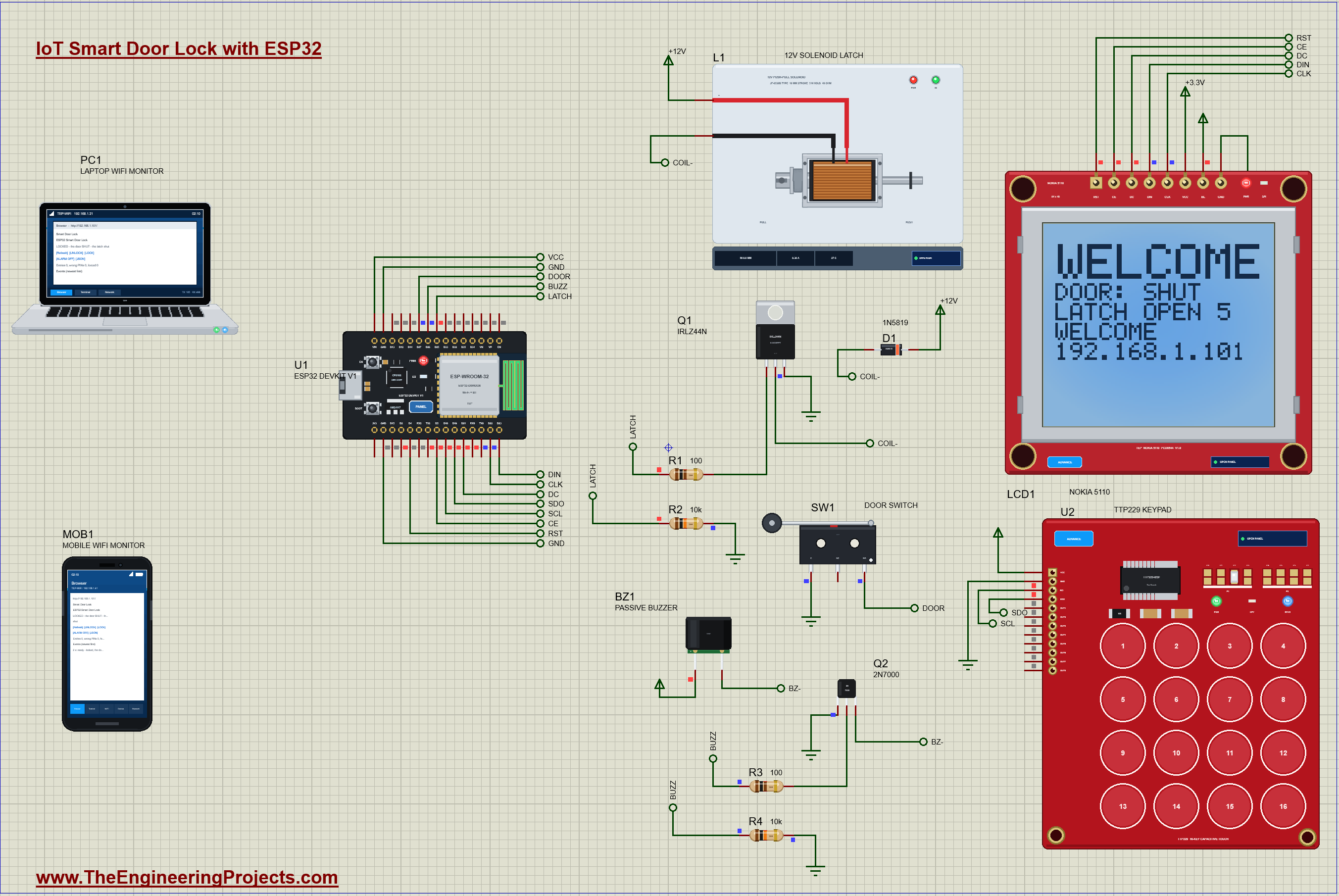
What Does This Smart Door Lock Do?
- A PIN keypad: 16 capacitive touch pads; the digits, DEL and OK, a doorbell pad and a LOCK pad. The PIN shows as stars on the LCD.
- A solenoid latch: the right PIN, or UNLOCK on the page, powers the latch for at most 5 seconds.
- Locks by itself: shutting the door after an entry locks it, and a door not opened within 5 seconds is locked again.
- A keypad lockout: three wrong PINs in a row put the keypad to sleep for 30 seconds.
- A forced-door alarm: the door opened while locked sounds a siren until ALARM OFF on the page or the right PIN.
- A doorbell and a dashboard: the bell plays a ding-dong and tells the page, which shows the lock, the door, the latch, a waiting visitor, the counts and the events.
It is a great project for anyone learning the ESP32, and a strong final-year project, because every part of it is something a real product needs. In the simulation, the keypad is touched on its pop-up, and the door is opened and shut with the micro switch's pop-up: Hold down is a shut door pressing the lever, Release is an open door.
Components Used in the Proteus Simulation
All the parts come from our Proteus libraries, each with its own tutorial. The project zip at the end includes every LIB and DLL file.
| Part | Proteus device | Library post | Connection |
|---|---|---|---|
| ESP32 DevKit V1 | ESP32 DEVKIT V1 | ESP32 DevKit V1 Library for Proteus | U1, TEP-WiFi 192.168.1.101 |
| TTP229 16-key touch keypad | TTP229ADVTEP | TTP229 Touch Keypad Library for Proteus | U2, SCL D18, SDO D19 |
| Nokia 5110 LCD (PCD8544) | NOKIA5110BLUEADVTEP | Nokia 5110 LCD Library for Proteus | LCD1, RST D4, CE D5, DC D21, DIN D23, CLK D22 |
| 12 V push-pull solenoid (the latch) | SOLENOID12VTEP | 12V Push-Pull Solenoid Library | L1, +12V and Q1's drain |
| IRLZ44N logic-level MOSFET | IRLZ44NTEP | N-MOSFET Library | Q1, gate from D25 |
| 2N7000 small MOSFET | Q2N7000TEP | N-MOSFET Library | Q2, gate from D26 |
| 1N5819 Schottky diode | DIODE1N5819TEP | Schottky Diode Library | D1, across the solenoid |
| Micro limit switch (the door sensor) | SWITCHLIMITTEP | Micro Limit Switch Library | SW1, NO on D27, C to GND |
| Passive buzzer | BUZZERPASSIVETEP | Passive Buzzer Library | BZ1, switched by Q2 |
| Resistors 100, 10k, 100, 10k | RESISTOR4BANDTEP | Resistor Library | R1 - R4, the gate resistors |
| Laptop WiFi Monitor | LAPTOP WIFI MONITOR | Laptop WiFi Monitor | PC1 |
| Mobile WiFi Monitor | MOBILE WIFI MONITOR | Mobile WiFi Monitor | MOB1 |
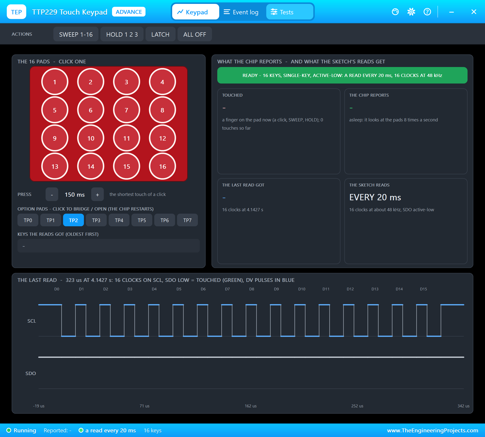
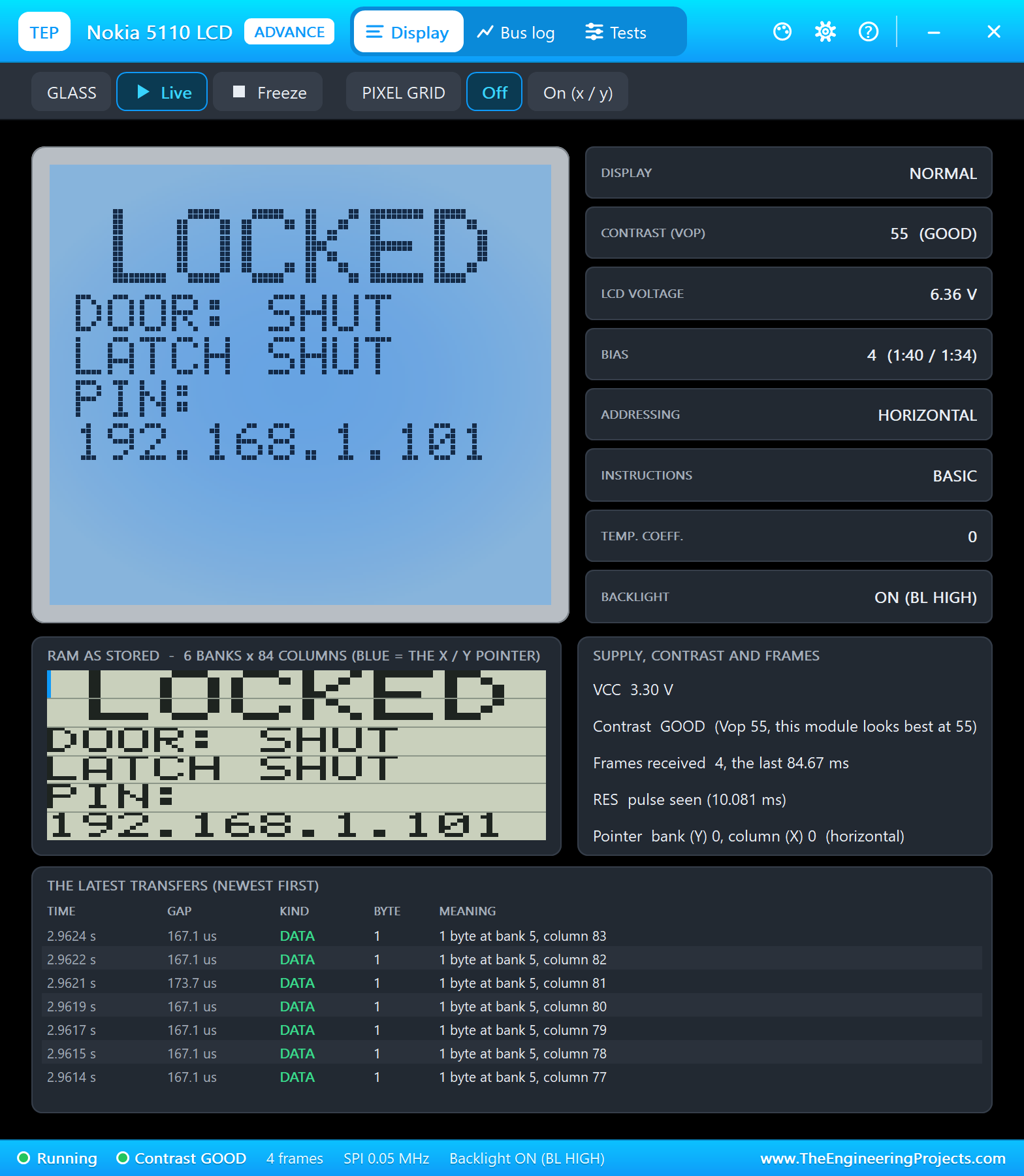
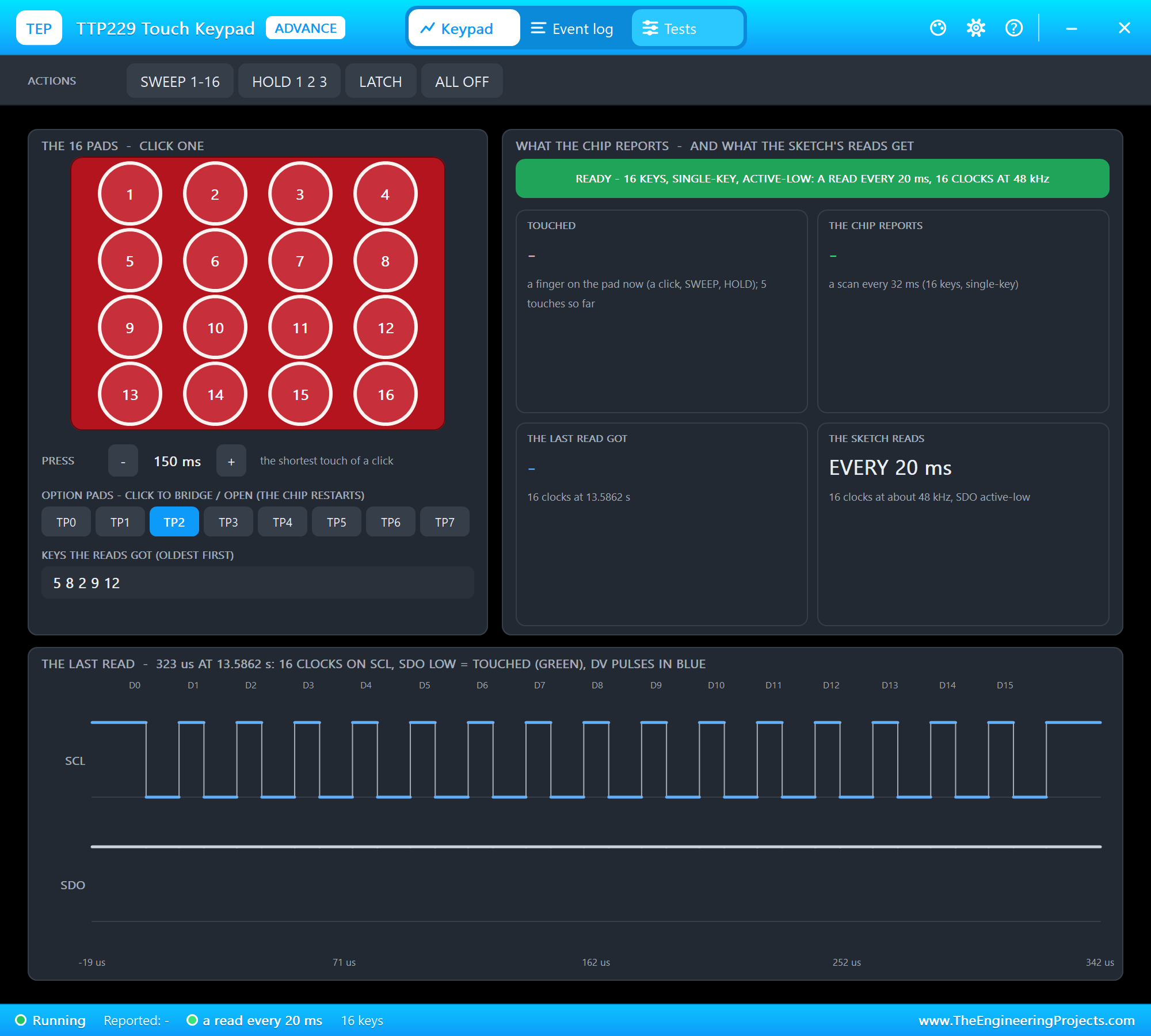
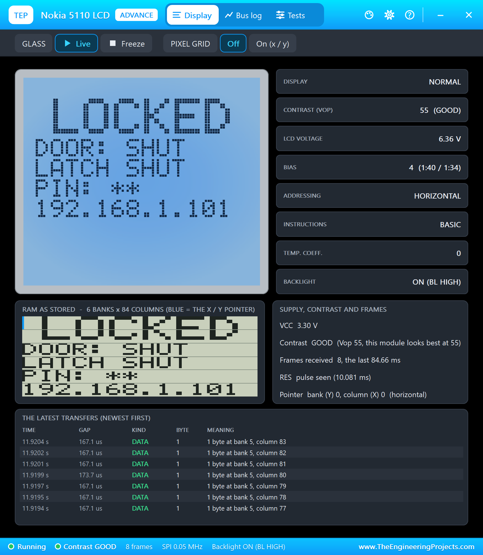
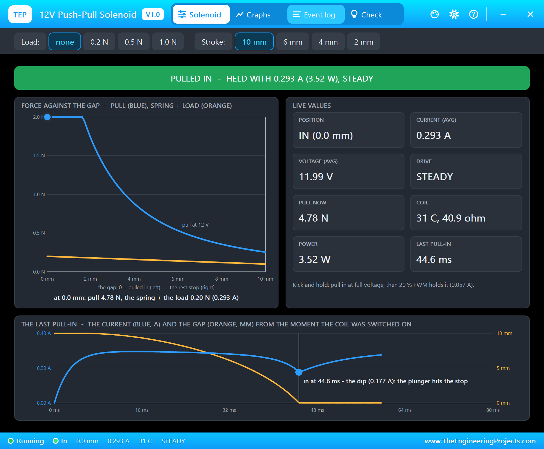
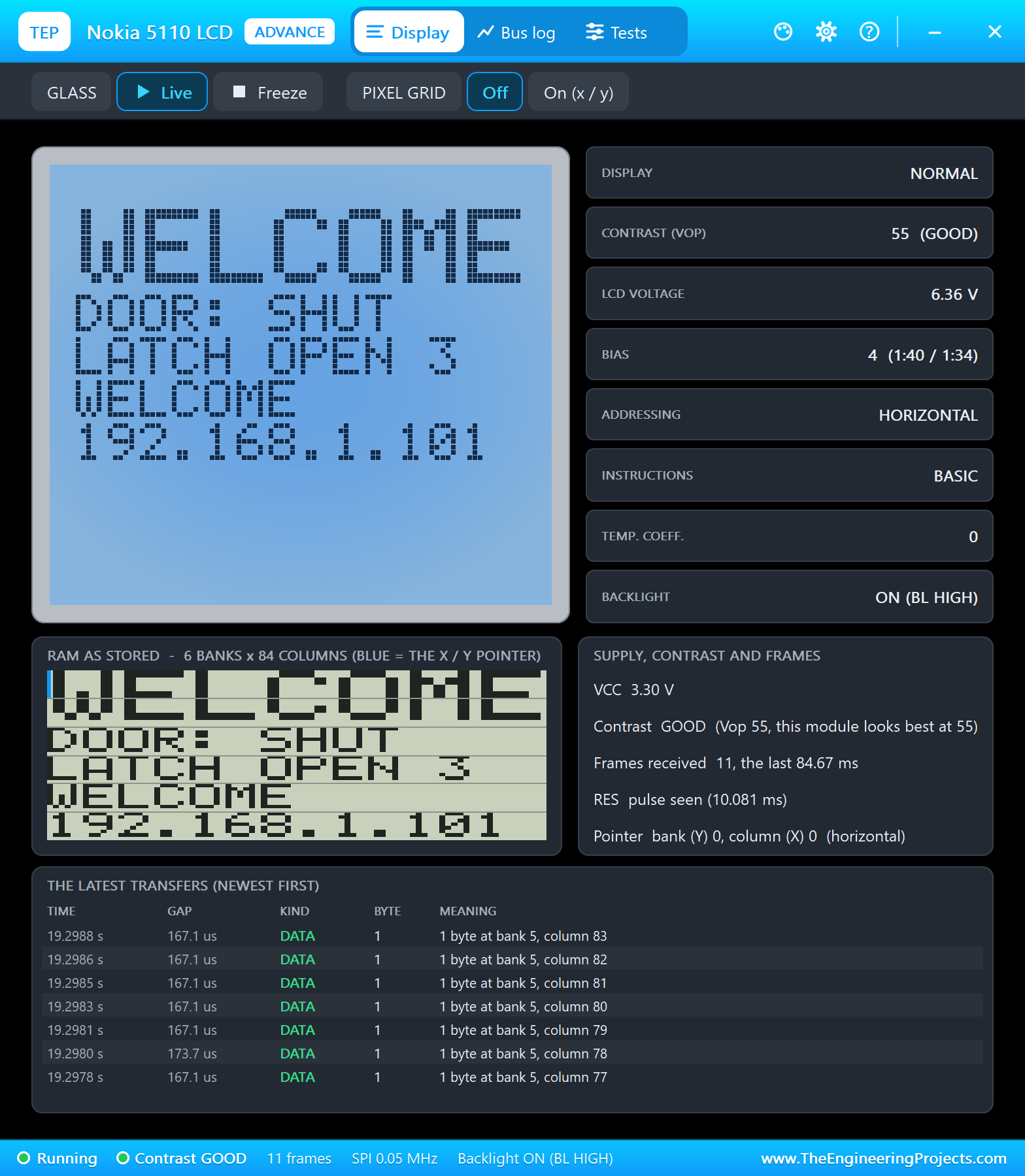
The keypad and the LCD are Advance models with pop-ups. The TTP229's pop-up has the 16 pads to click, the option pads TP0 to TP7, what the chip reports and a trace of the sketch's last read on SCL and SDO. The Nokia 5110's pop-up shows the glass, the controller's RAM bank by bank, the contrast and the LCD voltage, and every byte the sketch sends. The solenoid's pop-up shows the plunger's position, the coil current and the pull against the gap.
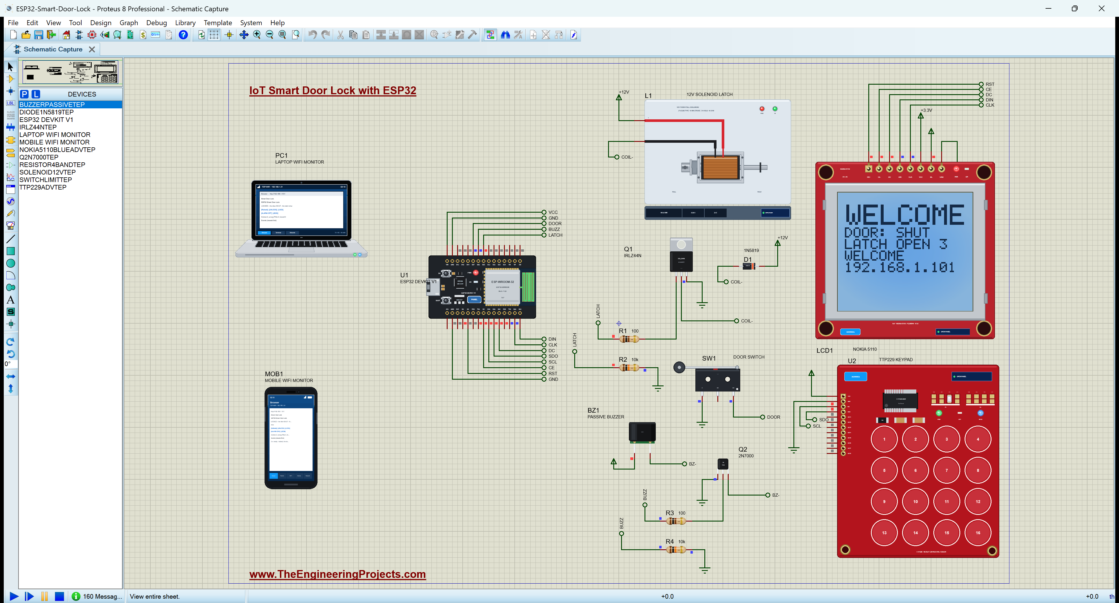
Proteus Simulation of the Smart Door Lock: the Circuit
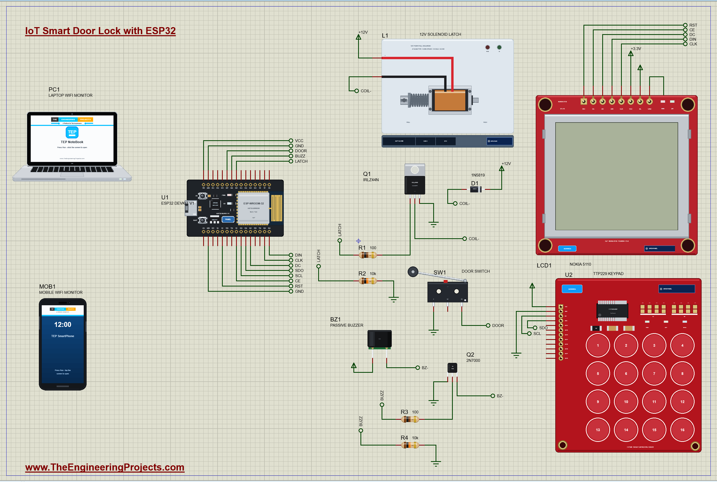
| Part | Pins | ESP32 DevKit V1 |
|---|---|---|
| U2 TTP229 | SCL / SDO | D18 / D19 |
| LCD1 Nokia 5110 | RST / CE / DC / DIN / CLK | D4 / D5 / D21 / D23 / D22 |
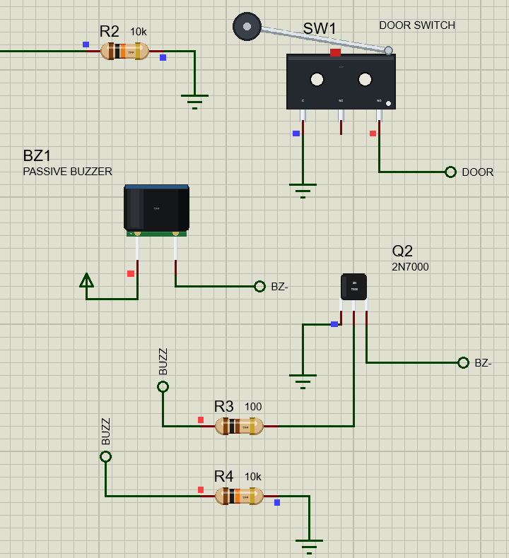
| Q1 IRLZ44N (the latch) | gate through R1 100 ohm (R2 10k to GND) | D25 |
| Q2 2N7000 (the buzzer) | gate through R3 100 ohm (R4 10k to GND) | D26 |
| SW1 limit switch | NO (C to GND) | D27 with the internal pull-up |
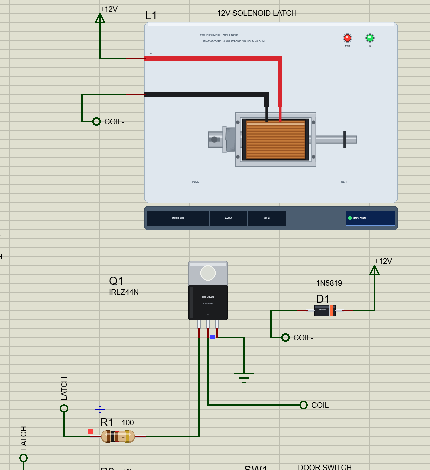
The solenoid's plus goes to +12V and its minus to the IRLZ44N's drain; the MOSFET's source is on ground, so the MOSFET switches the low side. The 1N5819 sits across the coil with its cathode on +12V. Each MOSFET gate gets a 100 ohm resistor in series and a 10k pull-down on the GPIO side: the 100 ohm limits the short current that charges the gate at each switch, and the 10k holds the gate at 0 V while the ESP32 boots and its pins float, so the latch can never open by accident at power-up. The passive buzzer sits between the 5 V rail and the 2N7000's drain.
Two supply notes. The Nokia 5110 is a 3.3 V part and runs from +3.3V. The TTP229 works from 2.4 to 5.5 V; in the simulation it runs from the 5 V rail, because its model reads its supply as a logic level, and the Nokia's backlight pin is on the 5 V rail for the same reason. On a real ESP32, power the TTP229 from 3.3 V, so that its SDO output never goes above the ESP32's 3.3 V, and the backlight from 3.3 V as well.
How the Smart Door Lock Works
The TTP229 Touch Keypad
The TTP229-BSF chip watches 16 copper pads for the small change of capacitance a finger makes. As the board comes, it reports only 8 pads; bridging the option pad TP2 enables all 16, which is the property OPTIONS=TP2 in the simulation. The chip sends its keys over a 2-wire serial interface that is not I2C: SCL is a clock from the ESP32 and SDO the data back. SCL rests HIGH; each falling edge puts the next key on SDO, key 1 first, and LOW means touched. So one read is 16 clocks, and the number of the clock that finds SDO LOW is the key. The chip scans its pads every 32 ms in 16-key mode, and if SCL stays still for 2 ms the interface starts again from key 1, so the reads must be at least 2 ms apart. The sketch reads every 20 ms: each read takes about 0.2 ms, and a touch of 150 ms is seen by about seven reads in a row, of which only the first counts.
| Pads | Meaning |
|---|---|
| 1 - 9 | the digits 1 to 9 |
| 10 | the digit 0 |
| 11 | DEL, the last digit off |
| 12 | OK, check the PIN |
| 13 | BELL, the doorbell |
| 16 | LOCK, lock now |
The Nokia 5110 LCD
The Nokia 5110 is an 84 x 48 pixel display with a PCD8544 controller. Its memory is arranged in 6 banks of 8 pixel rows, and each byte is one column of 8 pixels in a bank, the lowest bit at the top; 6 x 84 = 504 bytes make the whole picture. The interface is serial: CE LOW selects the chip, each rising edge of CLK reads one bit from DIN, most significant bit first, and DC, read with the eighth bit, tells a command (LOW) from picture data (HIGH). The sketch keeps a copy of the picture in the ESP32's RAM, draws into it, and sends all 504 bytes when anything changes; the controller's address moves on by itself after every byte.
The set-up sends six commands: the extended instruction set, the contrast, the temperature coefficient, the bias, back to the basic set, and the normal display mode. The contrast byte sets Vop, and the LCD voltage is VLCD = 3.06 V + 0.06 V x Vop. Worked example: Vop 55 gives 3.06 + 0.06 x 55 = 6.36 V, the voltage the model's pop-up reported, and 55 is the best value of this module.
Text from a 5x7 Font
Each character is five columns of 7 pixels, five bytes, with one empty column after it, so a line holds 14 characters and the screen 6 lines. Worked example: the letter L is 0x7F, 0x40, 0x40, 0x40, 0x40: 0x7F is a full column of 7 pixels and 0x40 is only the seventh pixel, so the bytes draw a vertical stroke and a foot. For the big status word at the top, the sketch doubles every pixel: each bit becomes two bits in a 16-bit number, which is split over two banks, and each column is sent twice. A full column 0x7F becomes 0x3FFF, 14 pixels: 0xFF in the upper bank and 0x3F in the lower one. Big characters are 10 pixels wide with 2 pixels between them, so WELCOME, 7 x 12 - 2 = 82 pixels, just fits in 84.
The Solenoid Latch and the MOSFET
The latch is a 12 V push-pull solenoid: a coil pulls a steel plunger in against a return spring, and the plunger is the bolt. Its coil is 40 ohm, so at 12 V it draws 12 / 40 = 0.3 A and takes 3.6 W. Such small solenoids are made for short pulses; held on for minutes they grow hot, which is why the sketch powers the latch for at most 5 seconds and releases it as soon as the door opens.
A GPIO pin can give a few milliamps, not 0.3 A at 12 V, so a MOSFET does the switching. The IRLZ44N is a logic-level MOSFET: its channel is fully on with a few volts on the gate, while its cousin the IRFZ44N needs about 10 V. The diode is there for the moment the MOSFET turns off: the coil's current cannot stop instantly, and without a path it would drive the drain voltage far above 12 V and destroy the MOSFET. The 1N5819 Schottky diode gives the current a loop through the coil, where it dies away in a few milliseconds; a Schottky diode drops only about 0.3 to 0.4 V and switches fast, which suits this job.
The Door Switch and Debouncing
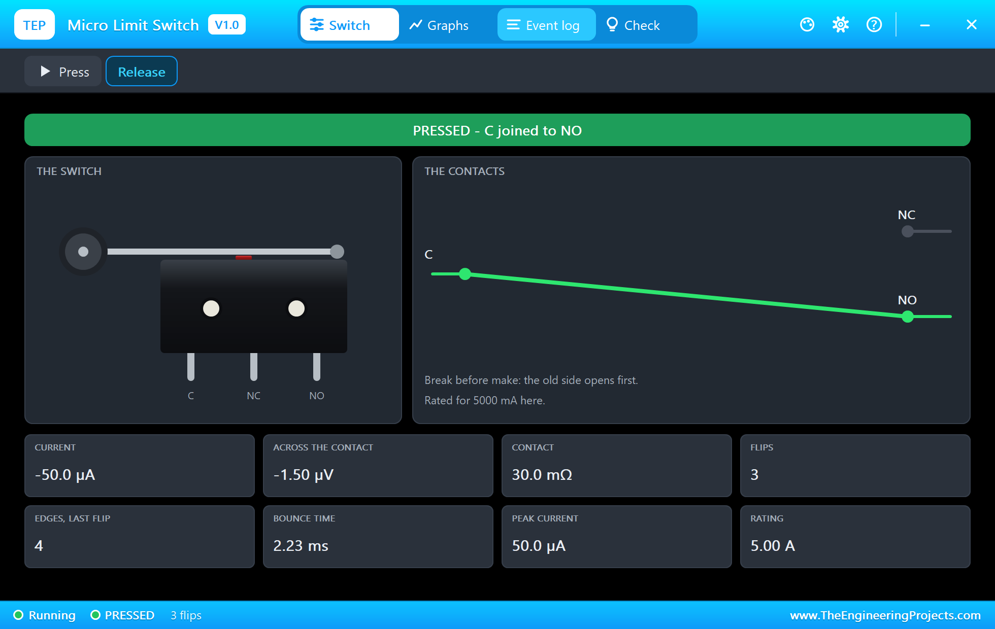
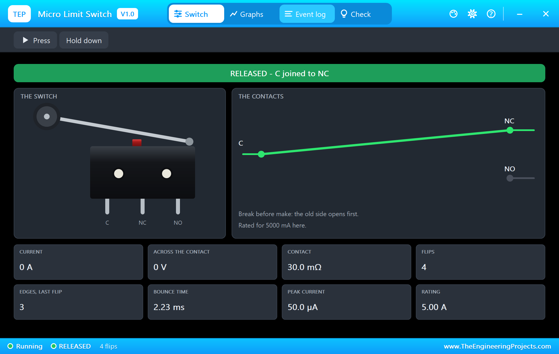
The micro limit switch is mounted on the frame so that the shut door presses its lever: C joins NO, and NO pulls D27 LOW against the ESP32's internal pull-up. Open the door and D27 reads HIGH. A mechanical contact does not change cleanly; it bounces for a few milliseconds, and each bounce would look like the door opening and shutting. The sketch accepts a new level only after it has held for 50 ms, far longer than any bounce and far shorter than any door.
The Passive Buzzer
An active buzzer has its own oscillator and beeps at one pitch when it gets power. A passive buzzer is just a small speaker element: it sounds at the frequency it is driven with, so the sketch can play notes. tone() makes a square wave on D26, and the 2N7000 switches the buzzer from the 5 V rail at that frequency. The sounds: a 2,500 Hz click for each pad, a low 400 Hz buzz for a wrong PIN, two rising notes of 1,500 and 2,000 Hz for welcome, a ding-dong of 1,047 Hz (C6) and 784 Hz (G5) for the bell, and for the alarm a siren that swaps between 2,200 and 1,400 Hz every 0.6 seconds.
The States of the Lock
| State | The LCD | Leaves it when |
|---|---|---|
| LOCKED | LOCKED | the right PIN or UNLOCK (UNLOCKED); the door opens (ALARM) |
| UNLOCKED | WELCOME | the door opens and shuts again, or 5 s pass unopened, or LOCK (LOCKED) |
| LOCKED OUT | WAIT and the seconds | 30 s pass (LOCKED); the door opens (ALARM) |
| ALARM - DOOR FORCED | ALARM! | ALARM OFF on the page (LOCKED) or the right PIN (UNLOCKED) |
The lockout is what makes a short PIN safe enough for a hobby lock. Worked example: a 4-digit PIN has 10,000 possibilities. With three tries every 30 seconds, trying them all would take 10,000 / 3 x 30 seconds, about 28 hours, and the forced-door alarm and the log would have told the owner long before.
The Arduino Code Explained
The whole sketch is included in the download. It needs no libraries beyond the ESP32 core's WiFi and WebServer: the keypad driver, the LCD driver and the font are in the sketch. At the top are the PIN and the timings:
const char PIN_CODE[] = "1234";                           // the door's PIN (change it here)
const unsigned long UNLOCK_MS = 5000;                     // the latch is powered for at most 5 s
const unsigned long LOCKOUT_MS = 30000;                   // after 3 wrong PINs the keypad sleeps for 30 s
const unsigned long OPEN_WARN_MS = 15000;                 // the door open longer than this = a reminder
const byte MAX_WRONG = 3;
Reading the Keypad
One read is 16 clocks; the first clock that finds SDO LOW names the key:
  for (byte i = 0; i < 16; i++) {
    digitalWrite(KEY_SCL, LOW);
    delayMicroseconds(5);
    if (digitalRead(KEY_SDO) == LOW && !key) key = i + 1;  // LOW = touched (single-key mode reports one pad)
    digitalWrite(KEY_SCL, HIGH);
    delayMicroseconds(5);
  }
A pad counts once, when it is first seen, however long the finger stays:
    byte pad = readKeypad();
    if (pad && pad != lastPad) onPad(pad);
    lastPad = pad;
Driving the Nokia 5110
Every byte goes out bit by bit, most significant first, with DIN set before each rising clock edge:
  for (byte i = 0; i < 8; i++) {                          // MSB first, DIN read on the rising CLK edge
    digitalWrite(LCD_DIN, (v & 0x80) ? HIGH : LOW);
    digitalWrite(LCD_CLK, HIGH);
    digitalWrite(LCD_CLK, LOW);
    v <<= 1;
  }
const byte init[] = {0x21, 0x80 | 55, 0x04, 0x14, 0x20, 0x0C}; // extended set, Vop 55, temp. coefficient 0, bias 1:48, basic set, normalThe big letters double each bit of a font column into two bits, as in the worked example:
      unsigned int tall = 0;                              // each bit twice: 7 rows become 14
      for (byte r = 0; r < 8; r++) if (bits & (1 << r)) tall |= 3u << (2 * r);
The Lock's Logic
Unlocking clears the wrong-PIN count, starts the 5-second window and powers the latch; three wrong PINs start the lockout:
  state = UNLOCKED; wrong = 0; doorWasOpened = false; visitor = false;
  setLatch(true); unlockedAt = millis(); entries++;
if (wrong >= MAX_WRONG) { state = LOCKOUT; lockoutAt = millis(); wrong = 0; event("3 wrong PINs - the keypad locked out for 30 s"); }The door switch is debounced, and an opening is either an entry or a forced door:
  bool raw = digitalRead(DOOR_PIN) == LOW;
  if (raw != doorRaw) { doorRaw = raw; doorChange = t; }
  if (raw != doorShut && t - doorChange >= 50) {
if (state == UNLOCKED) { doorWasOpened = true; event("the door opened"); setLatch(false); } // the latch can rest now
else if (state != ALARM) { state = ALARM; forced++; event("DOOR FORCED - opened while locked"); }The timers read millis() afresh, and the siren swaps its two notes every 0.6 seconds:
  t = millis();
  if (state == UNLOCKED && latchOn && t - unlockedAt >= UNLOCK_MS) {
    if (doorWasOpened) setLatch(false); else lockNow("not opened in 5 s");
  }
if (state == ALARM && t - lastBeep >= 600) { lastBeep = t; static bool hi; hi = !hi; tone(BUZZ_PIN, hi ? 2200 : 1400); }That fresh millis() is there for a reason we found in testing, explained in the results. The pages are / (the dashboard), /unlock, /lock, /alarmoff and /data (JSON), and every event, from the keypad, the door or the page, goes into the log with its time.
How to Run the Proteus Simulation
- Download the project zip below and install the library files (the steps are under the download button).
- Open ESP32-Smart-Door-Lock.pdsprj from the Proteus Simulation folder. Keep the .hex and DLL files next to it.
- Press Play. Open the limit switch's pop-up with the small white dot on its body and press Hold down: the door is shut.
- In the TTP229's pop-up touch 1, 2, 3, 4 and 12 (OK): WELCOME, and the latch opens for 5 seconds.
- Press Release (the door opens) and Hold down again (it shuts): locked again.
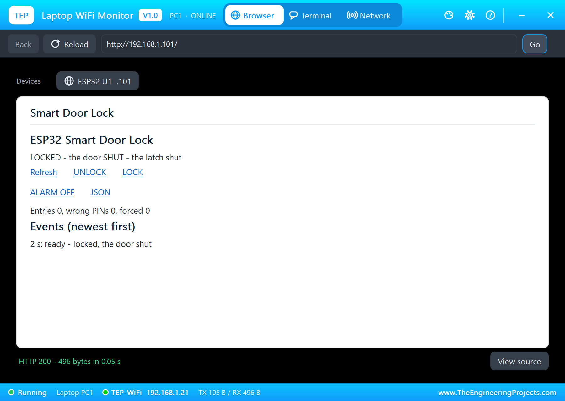
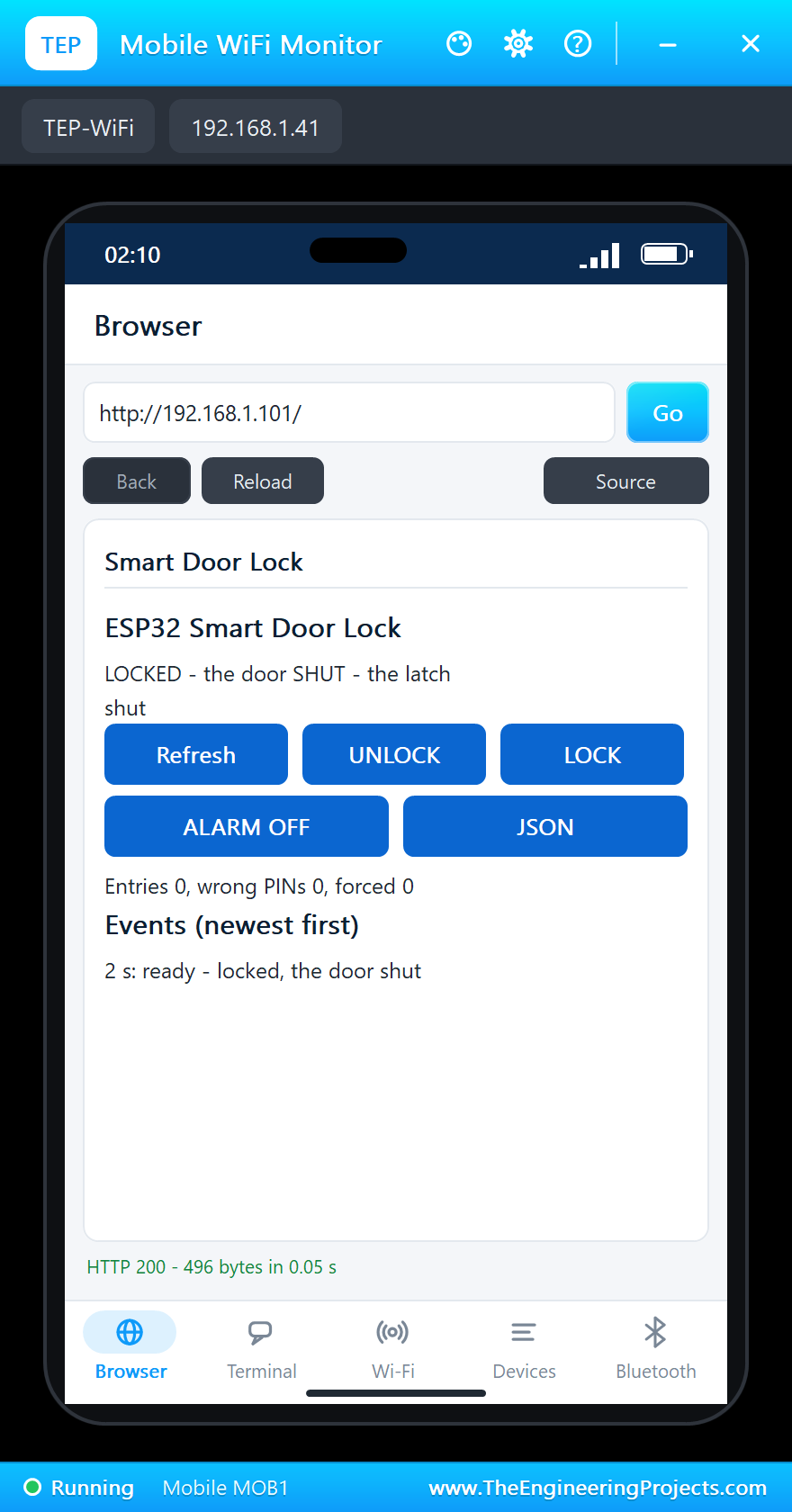
- Open the Laptop WiFi Monitor (PC1) or the Mobile WiFi Monitor (MOB1), press Go, and try UNLOCK, the BELL pad (13), three wrong PINs and a Release while locked.
Proteus Simulation Results
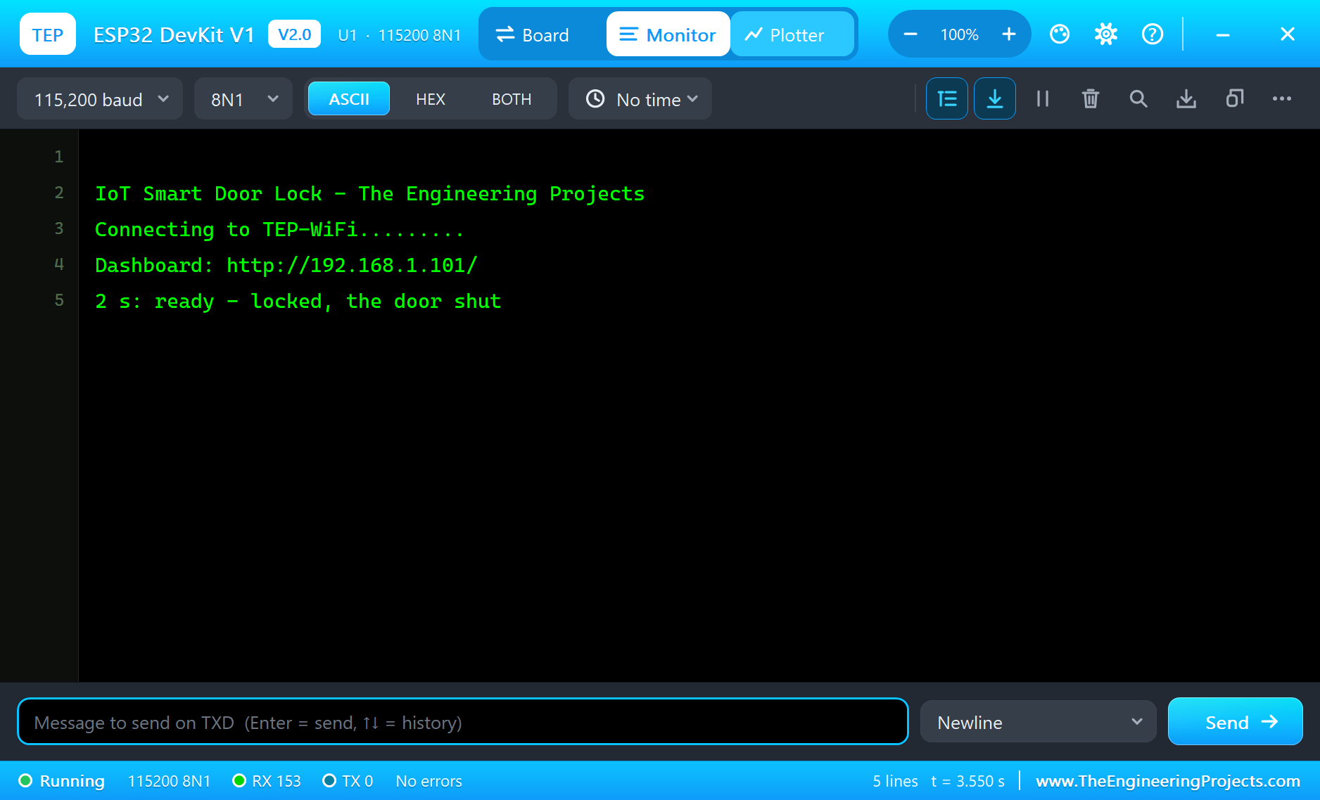
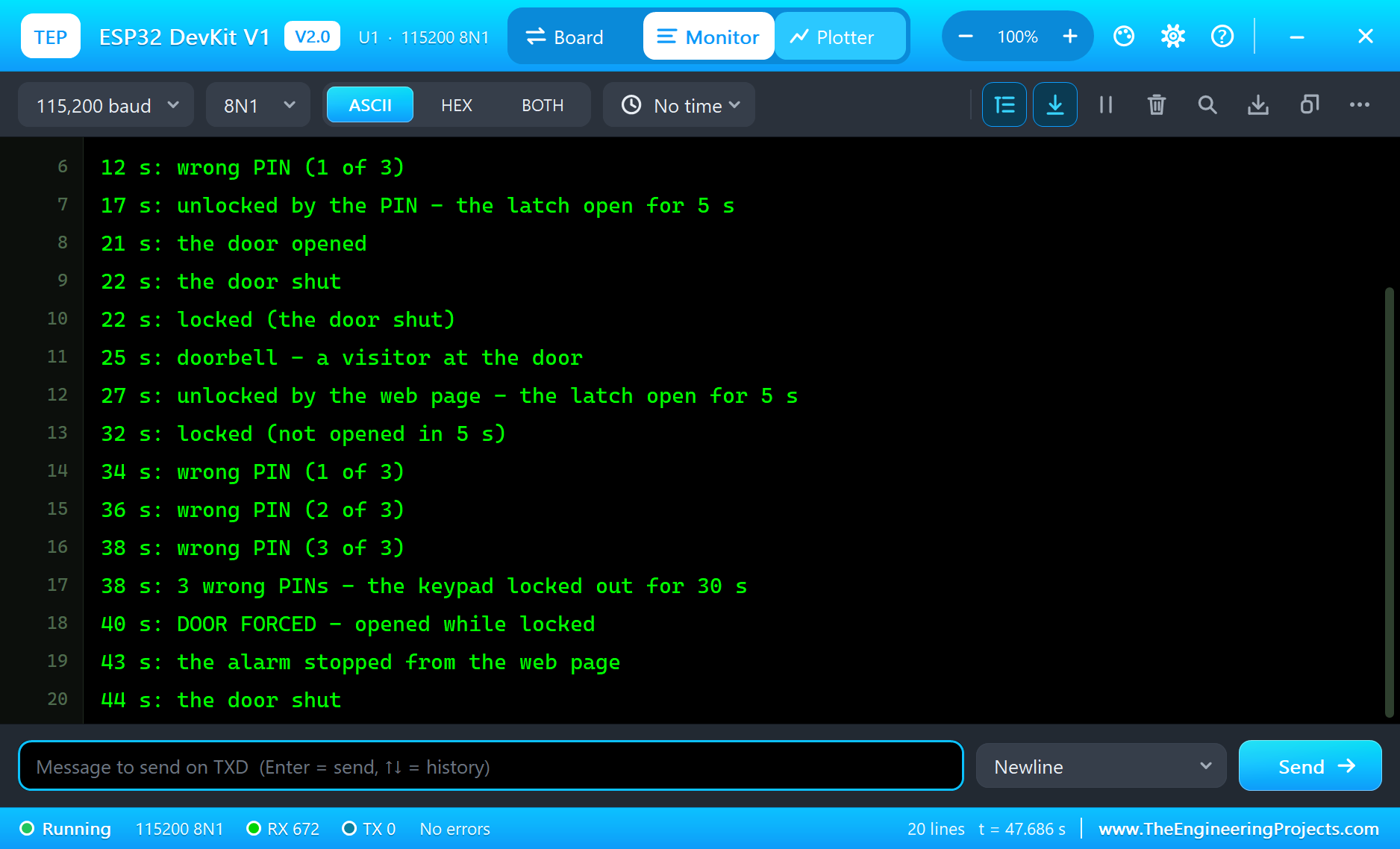
Here is one complete run of the simulation, with the numbers from our final test run; the times are simulation seconds since the ESP32 started. While the board joined TEP-WiFi, the switch was held down, so at 2 seconds the sketch reported "ready - locked, the door shut". The LCD showed LOCKED with the door, the latch, the PIN line and the IP address, its contrast at Vop 55, 6.36 V, as in the worked example.
A Wrong PIN, Then the Right One
First, pads 5, 8, 2, 9 and OK. The keypad's pop-up listed the keys the reads got, 5 8 2 9 12, and at 12 seconds the sketch logged "wrong PIN (1 of 3)" with a low buzz and WRONG PIN 1/3 on the LCD. Then 1, 2, 3 and 4: the LCD showed the digits only as stars.
OK, and at 17 seconds "unlocked by the PIN - the latch open for 5 s". The IRLZ44N switched on, the solenoid pulled its plunger in within 44.6 ms and held it at 0.293 A, 3.52 W, close to the 0.3 A and 3.6 W of the worked example. The LCD said WELCOME and counted the latch's seconds down.
The Door Opens and Shuts
Release on the switch's pop-up opened the door: "the door opened" at 21 seconds, and the sketch released the latch at once to spare the coil. Hold down shut it again at 22 seconds: "the door shut" and "locked (the door shut)". The switch's pop-up showed its bounce, 2.23 ms, far inside the sketch's 50 ms.
A Visitor Let In from the Phone
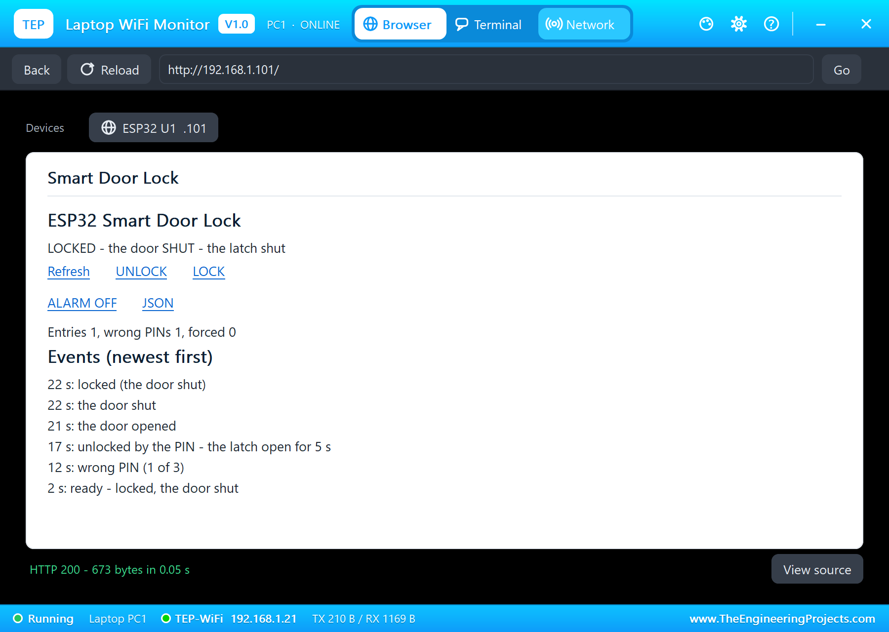
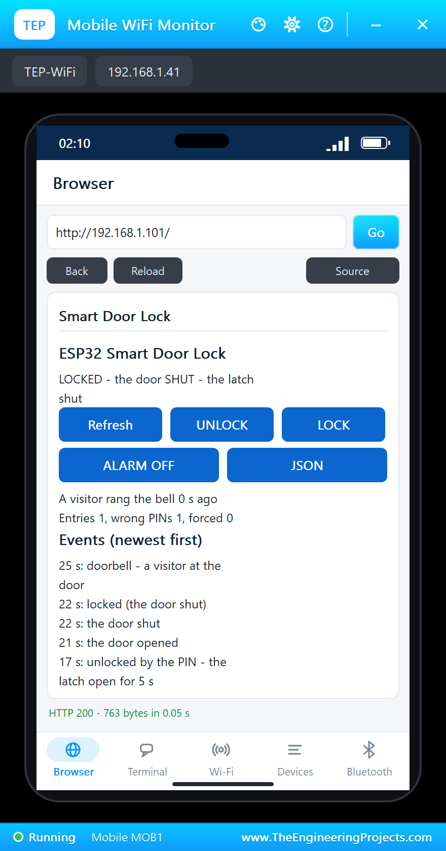
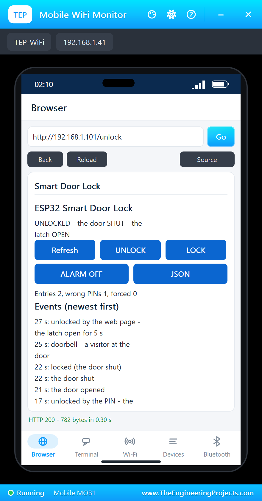
At 25 seconds, the BELL pad: a ding-dong, and "doorbell - a visitor at the door". The phone's page showed the visitor; UNLOCK on the phone at 27 seconds opened the latch, "unlocked by the web page". Nobody opened the door, so at 32 seconds the lock closed by itself: "locked (not opened in 5 s)".
Three Wrong PINs
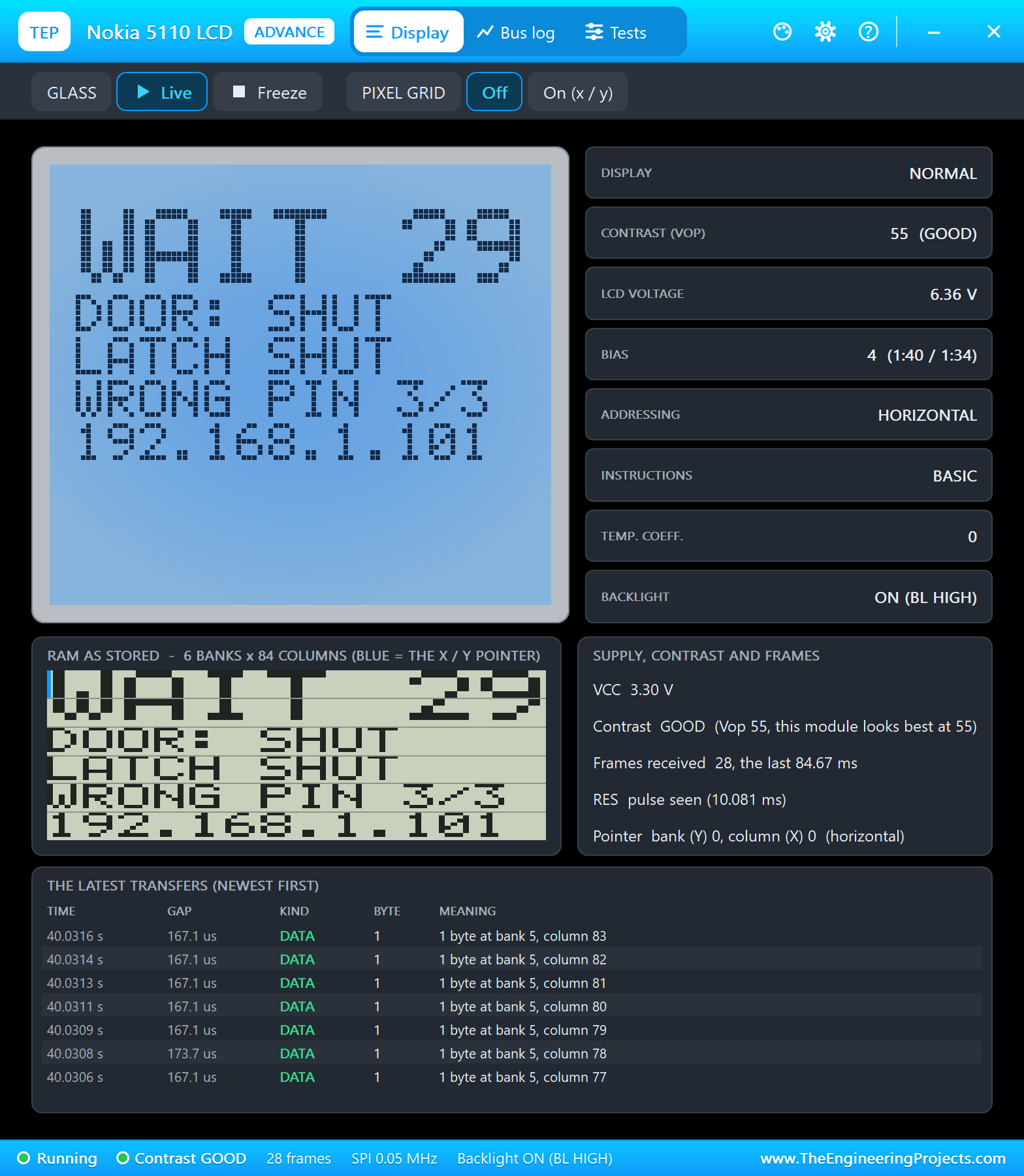
Then 9999 and OK three times: "wrong PIN" 1, 2 and 3 of 3 at 34, 36 and 38 seconds, and "3 wrong PINs - the keypad locked out for 30 s". The LCD showed WAIT and the seconds left, and pads touched now got only a short beep.
The Door Forced
Last, someone forces the door while it is locked: Release on the switch at 40 seconds. "DOOR FORCED - opened while locked": the siren swapped its two notes, the LCD said ALARM! and FORCED OPEN, and the page showed the alarm with the counts, 2 entries, 4 wrong PINs and 1 forced door.
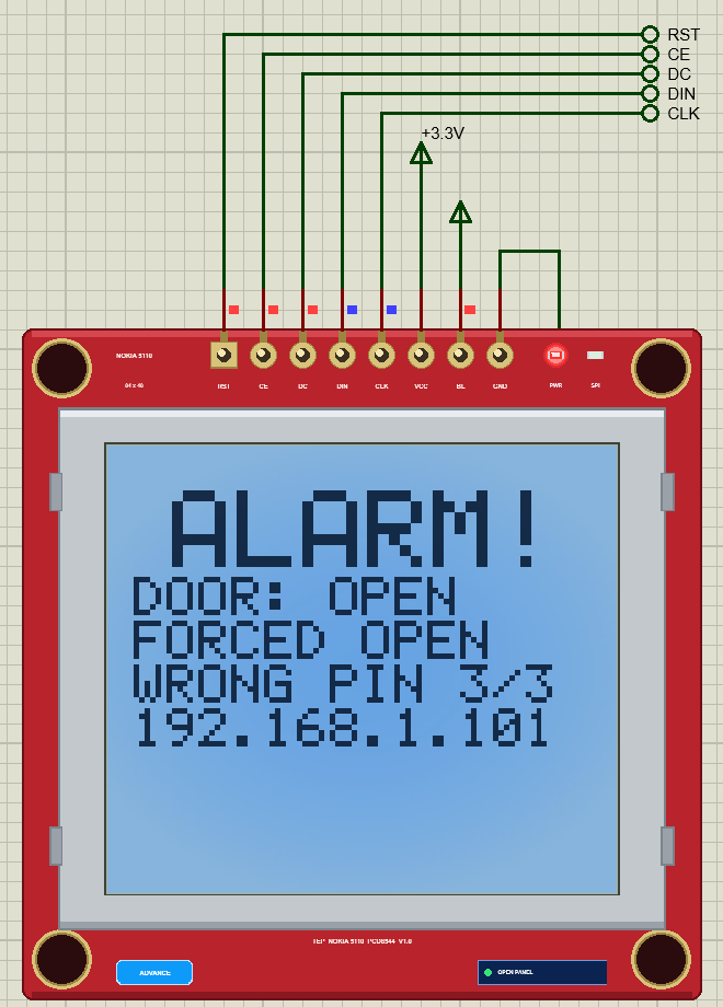
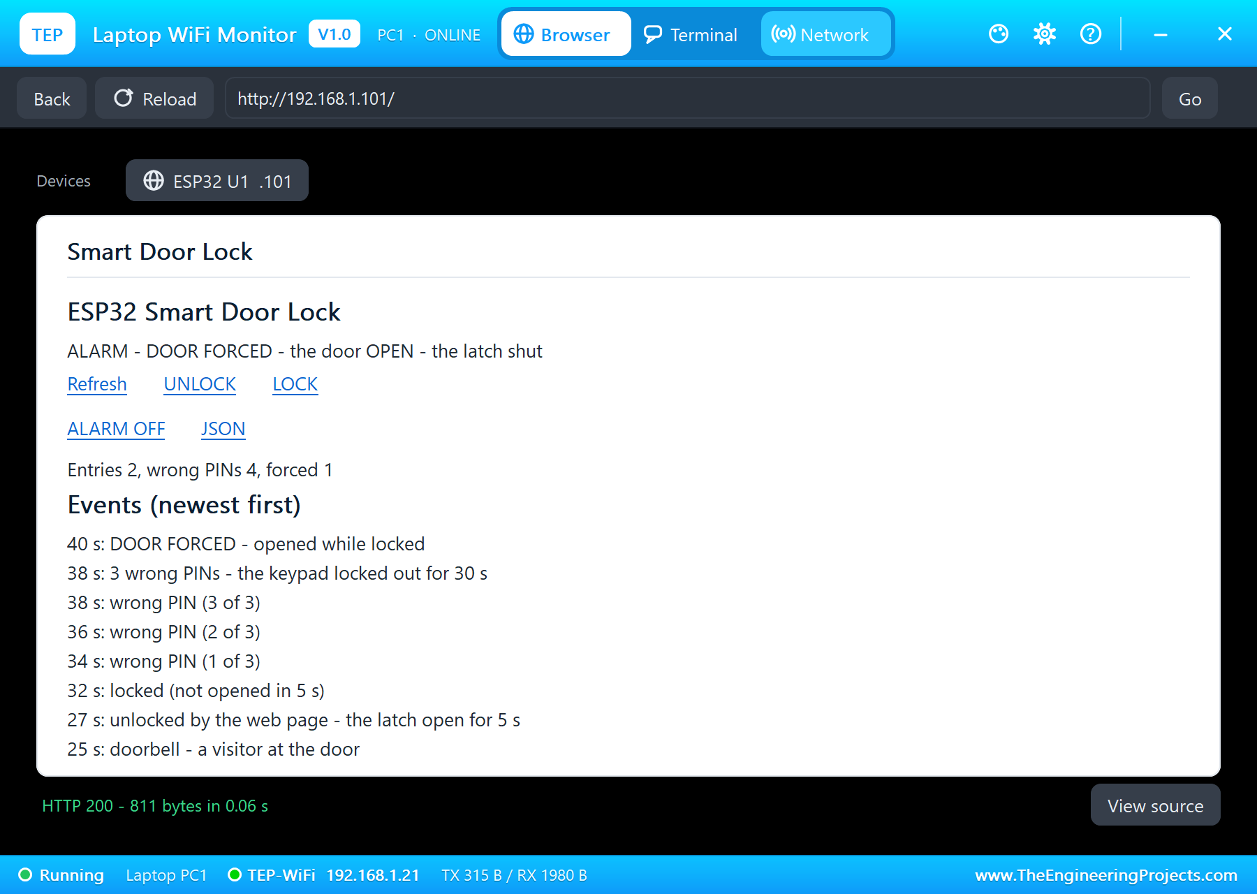
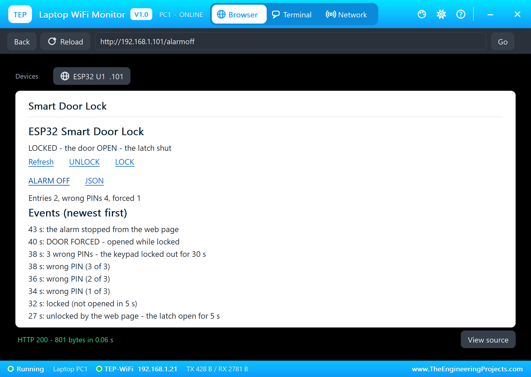
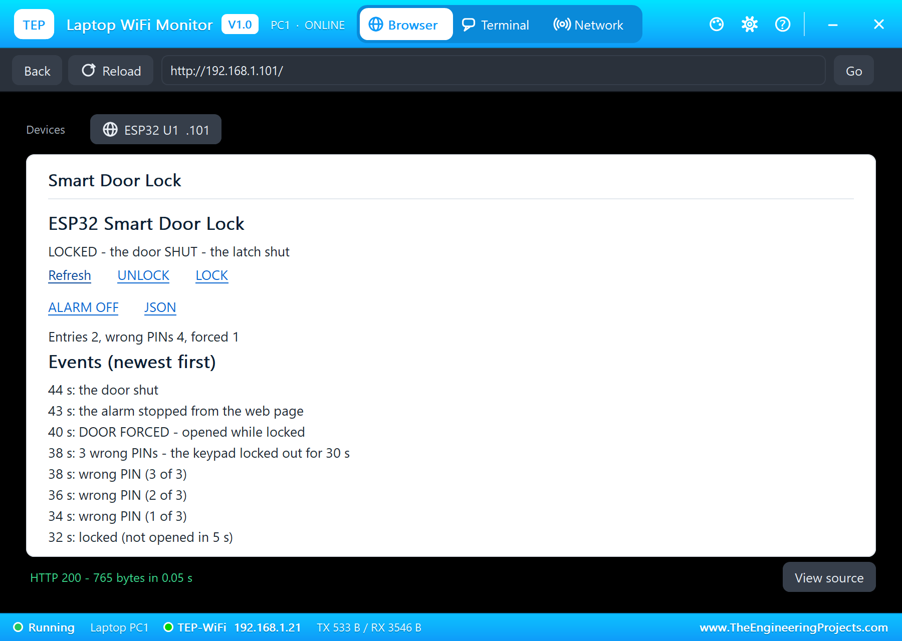
ALARM OFF on the laptop at 43 seconds stopped the siren, "the alarm stopped from the web page", and the lock went back to LOCKED; Hold down shut the door at 44 seconds.
The serial monitor holds the whole story:
In all, 48 seconds of simulation took about 6 minutes on our PC with all the screenshots, and the TTP229 counted 26 keys read with none missed. Our earlier test runs found three things worth knowing. The TTP229 on a 3.3 V terminal reported NO POWER, and its floating SDO read as a ghost key 1; the Nokia's backlight stayed off for the same reason, so both moved to the 5 V rail. And the 30-second lockout ended the moment it began: the lockout's start time was set after the beep, later than the loop's own reading of millis(), so the unsigned subtraction wrapped round to a huge number. Reading millis() again before the timers fixed it, which is why that line is in the sketch.
Download the Project Files
Click the button below to download IoT-Smart-Door-Lock-ESP32-Proteus-Simulation-v1.0.zip (about 5.2 MB, without the source code of the models):
IoT Smart Door Lock with ESP32 - Proteus Simulation V1.0- Proteus Simulation: ESP32-Smart-Door-Lock.pdsprj, ESP32_Smart_Door_Lock.hex and copies of the models.
- Arduino Code: ESP32_Smart_Door_Lock.ino, the complete sketch.
- Proteus Library Files: the LIB files of the ESP32 DevKit V1, the TTP229, the Nokia 5110, the solenoid, the MOSFETs, the Schottky diode, the limit switch, the passive buzzer, the resistor and the two WiFi Monitors.
- Proteus Model Files: the DLL models.
- README.txt: the installation steps, the properties, the test results and the links to every library post.
No Proteus yet? Read How to Download and Install Proteus 7 and 8. New to libraries? Follow How to Install a New Library in Proteus.
How to Install the Project Files
- Close Proteus and extract the whole zip file, for example to your Desktop.
- Copy the files from Proteus Library Files into the LIBRARY folder of Proteus.
- Copy the files from Proteus Model Files into the MODELS folder.
- Start Proteus and open the project from the Proteus Simulation folder.
Changing the Code
To change the sketch, install the TEP Boards for Proteus add-on from the ESP32 DevKit V1 Library for Proteus post, open the sketch in the Arduino IDE, choose ESP32 DevKit V1 (TEP Proteus), export the compiled binary and set the board's PROGRAM property to the new .hex file. The PIN and the timings are at the top. The same sketch runs on a real ESP32 Dev Module. For another ESP32 project with a dashboard, see our IoT Home Automation with ESP32 and IR Remote.
Ideas to Extend the Project
- Keep several PINs, one for each member of the family, and log who came in.
- Store the PIN in the ESP32's flash and change it from the page after the old one is typed.
- Add an RFID reader, so a card opens the door as well as the PIN.
- Send a message to a phone when the bell rings or the door is forced.
- Use a fail-secure electric strike or a motorised bolt for a real door.
- Dim the LCD's backlight with PWM at night and wake it with the first touch.
From Simulation to Real Hardware
- Power the TTP229 and the backlight from 3.3 V: the ESP32's pins are not 5 V tolerant.
- Give the solenoid its own 12 V supply: about 1 A is plenty; join its ground to the ESP32's ground.
- Keep the diode right at the solenoid: the turn-off spike is born in the coil, so the shorter its loop, the better.
- Mind the duty cycle: a push-pull solenoid is for short pulses; a door that stays unlocked needs a lock made for it.
- Think about a power cut: this latch locks when the power fails (fail-secure); fire rules may ask for doors that unlock instead (fail-safe).
- A hobby lock is not a certified lock: use it for a cabinet, a workshop or learning, not for a front door.
Troubleshooting
- Pads 9 to 16 do nothing: the TTP229 is in 8-key mode; set OPTIONS=TP2.
- Every PIN is wrong: the touches come too fast, or a key was read during the chip's power-on calibration; touch the pads one at a time.
- The LCD is blank or dark: CE, DC, DIN or CLK swapped, or Vop far from 55.
- DOOR FORCED at once: the door switch was not held down when the sketch started.
- No sound: the buzzer's minus is not on Q2's drain, or the buzzer has no 5 V.
Limitations of the Simulation
- The touches and the door come from the pop-ups; a pad click is a 150 ms touch.
- The TTP229 and the LCD's backlight run from the 5 V rail in the simulation, as explained in the circuit section.
- The network is simulated, and the times in this tutorial are simulation time; with the analog parts this simulation runs slower than real time.
- ESP32 is a name of Espressif Systems; this project is not made or endorsed by them or by Labcenter. A hobby door lock is not a certified security product.
So, that was all about the IoT Smart Door Lock with ESP32 - Proteus Simulation. I hope it helps you build your own: a touch keypad read over two wires, a graphic LCD driven byte by byte, a solenoid switched safely by a logic-level MOSFET with its diode, a debounced door switch, tones from a passive buzzer, and a lock that thinks in states, all tested in a simulation before a single screw goes into a door. More IoT projects with the ESP32 and the Raspberry Pi 5 are coming in this series. If you have any questions, ask in the comments and I will help you out. Till the next tutorial, take care and have fun!