Hello friends, I hope you all are doing great. Today, I am going to share the new Micro Hydro Generator Library for Proteus Simulation, the next library of our renewable energy series. If you have searched for a Proteus simulation of a water turbine generator, the small F50 generator that screws into a half-inch water pipe and makes 12 V from the water's pressure, this library brings it into Proteus: the water, the turbine, the generator, its regulator and the load, all solved together.
Micro Hydro Generator Library for Proteus Simulation
Latest version: V1.0 (November 2026, this tutorial)
Other power libraries: LiPo Battery · Single Cell Battery · CR2032 Coin Cell · Solar Panel · MC34063 Buck · MC34064 Boost · 12V Solar Panel · 6V Mini Solar Panel · 3-Phase PM Generator · Vertical-Axis Wind Turbine
Helping Tools
- Serial Monitor Advance: a serial terminal window for the UART of your board
- Serial Monitor Expert: the serial monitor with extra debugging tools
- LCD Library for Proteus V3.0: 16x2, 20x4 and I2C LCDs to show your readings
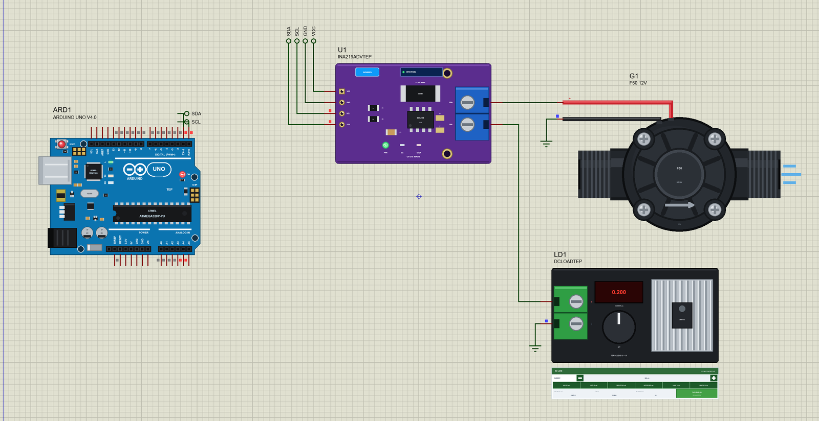
The F50 is drawn at its true size, 86.5 mm from thread to thread, and at run time the water leaves its outlet on your sheet. The simulation model follows the maker's own curve of voltage against pressure and adds what the curve leaves out: the runner slows down under load, so the voltage falls, and the 12 V regulator holds only while the water can turn the generator fast enough. In the demo an Arduino reads the generator's volts and amps through our INA219 while the tap opens step by step.
NOTICE: Our team has put a lot of effort into these small parts: the bodies, the animation and the pop-ups are all our own design, and you get them free. Your feedback is the fuel that keeps us going, so please tell us what you think in the comments below or in the Motor Driver board of our forum. And if our free libraries help you, you can buy us a coffee. So, let's get started with the Micro Hydro Generator Library for Proteus Simulation:
What is a Micro Hydro Generator?
A micro hydro generator turns the energy of flowing water into electricity on a very small scale. The F50 is the smallest kind you can buy: a black plastic body with a 1/2 inch thread at each end, so it fits straight into a household water pipe, a garden hose or the outlet of a water tank. Inside, a nozzle squirts the water at the blades of a small runner, the runner turns a permanent-magnet generator on the same shaft, and a rectifier turns its three-phase output into DC. The water leaves through the other thread.
It comes in two versions. The F50-12V has a small regulator board inside and gives 12 V for a 12 V lamp, a 12 V battery through a charge controller or a converter to 5 V. The F50-80V has no regulator: its voltage simply follows the water pressure, up to about 80 V with nothing connected. People use them for off-grid lights fed by a stream or a tank, for school projects on renewable energy, and for small sensors that power themselves from the water they measure.
| F50-12V micro hydro generator (the maker's sheet) | |
|---|---|
| Output | 12 V maximum (regulated), 220 mA or more at 12 V |
| Winding | line resistance 10.5 ohm (+- 0.5 ohm), insulation 10 Mohm |
| Water pressure | starts at 0.05 MPa; 0.6 MPa at most with the outlet closed, 1.2 MPa with it open |
| Without the regulator | the voltage follows the pressure: 5 V at 0.1 MPa, 38 V at 0.3 MPa, 80 V at 1.2 MPa |
| Size and thread | 86.5 mm from end to end, 49 mm across, G1/2 threads (20 mm), about 90 g |
| Noise | 55 dB or less |
How Water Pressure Becomes Electricity
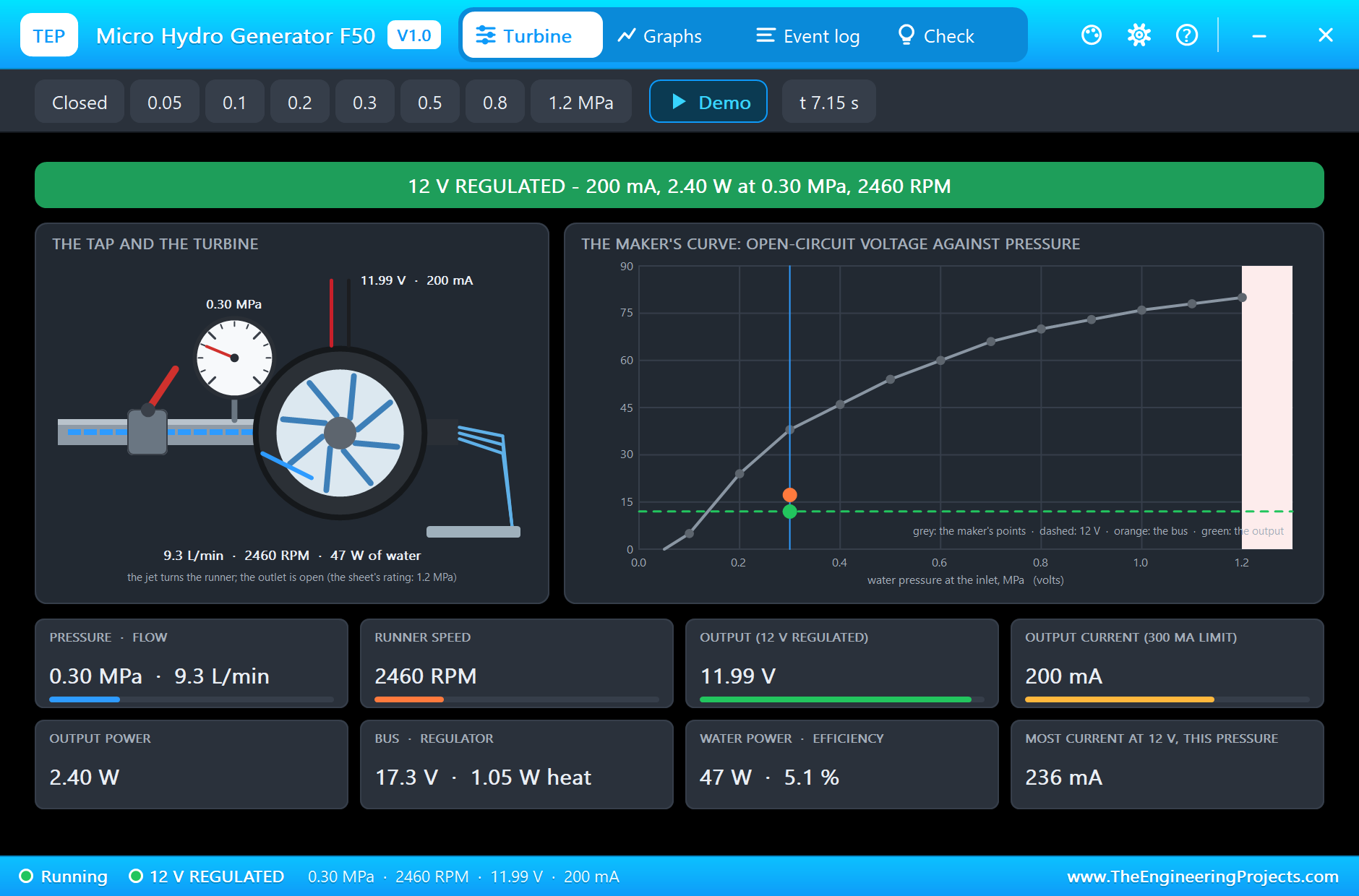
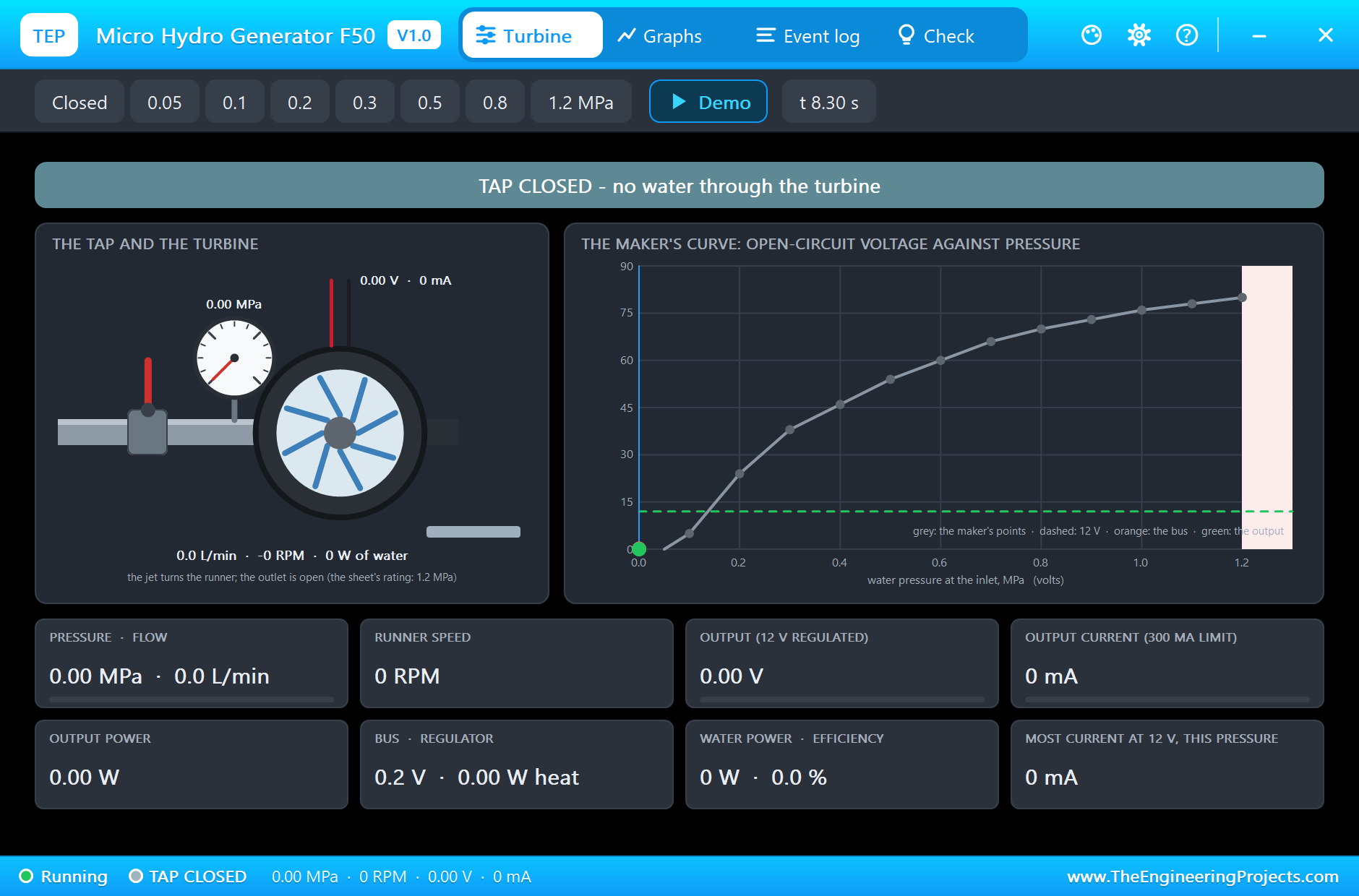
Pressure is stored energy. One megapascal (MPa) is ten bar, the pressure under about 100 metres of water; a house usually has between 0.2 and 0.4 MPa at the tap. When the water leaves a nozzle, that pressure turns into speed: the jet's velocity grows with the square root of the pressure, and so does the flow through the nozzle. The water's power is the pressure times the flow, so it grows faster than the pressure itself: in the simulation 0.3 MPa pushes 9.3 litres a minute through the nozzle, about 47 W of water.
The jet hits the runner's blades. With the runner held still, the jet pushes hardest: that is the stall torque, and it grows with the pressure. As the runner speeds up, its blades run away from the water and the push falls, until at the free-running speed the jet only just covers the friction. That free speed sets the generator's open-circuit voltage, and it is exactly what the maker's curve shows: 5 V at 0.1 MPa, 24 V at 0.2 MPa, 38 V at 0.3 MPa and 80 V at 1.2 MPa. Our simulation model passes through all twelve points of that curve.
Now connect a load. The current through the generator's winding makes a braking torque on its shaft, so the runner slows down until the jet's push and the generator's brake are equal. A slower runner means a lower voltage, and the winding's 10.5 ohm takes a little more. That is why a micro hydro generator is no battery: the more current you take, the lower its voltage goes, and how far it falls depends on the water pressure.
The 12 V Regulator and What It Can Give
The F50-12V puts a regulator after the rectifier. As long as the generator's voltage (the bus) stays above about 13.5 V, the output stays at 12 V whatever the load does. When a load asks for more current than the water can give at 12 V, the bus falls under 13.5 V, the regulator runs out of headroom and the output follows the bus down. So the real question for any F50 project is: how much current at 12 V can the water give? The simulation answers it at every pressure: 88 mA at 0.2 MPa, 236 mA at 0.3 MPa, and the regulator's 300 mA limit from about 0.4 MPa.
A regulator of this kind is not free either. It drops the difference between the bus and 12 V, and that difference times the current becomes heat. At a high pressure with a modest load the bus sits far above 12 V, so the regulator can get hot even while the output looks perfect. The pop-up shows that heat all the time, and the Event log warns when it passes 2 W. The F50-80V leaves all of this to you: no regulator, the full voltage of the curve, and your own converter after it.
Features of the Micro Hydro Generator Library for Proteus Simulation
- The F50 at true scale: the front of the body with its ribbed cover and four screws, the G1/2 threads, the red and black leads; at run time the water leaves the outlet, longer streaks with more flow.
- The maker's curve: the open-circuit voltage passes through all twelve points of the F50 sheet, from the start at 0.05 MPa to 80 V at 1.2 MPa.
- A real load line: the runner slows under load, the 10.5 ohm winding and the rectifier drop their share, so the voltage falls with the current as on the real generator.
- Two models: TYPE 12V (the F50-12V with its 12 V regulator: dropout, current limit, heat) and TYPE 80V (the F50-80V, no regulator).
- The water in your hands: the PRESSURE property, chips in the pop-up (closed, 0.05 to 1.2 MPa) or a built-in demo that opens the tap in steps.
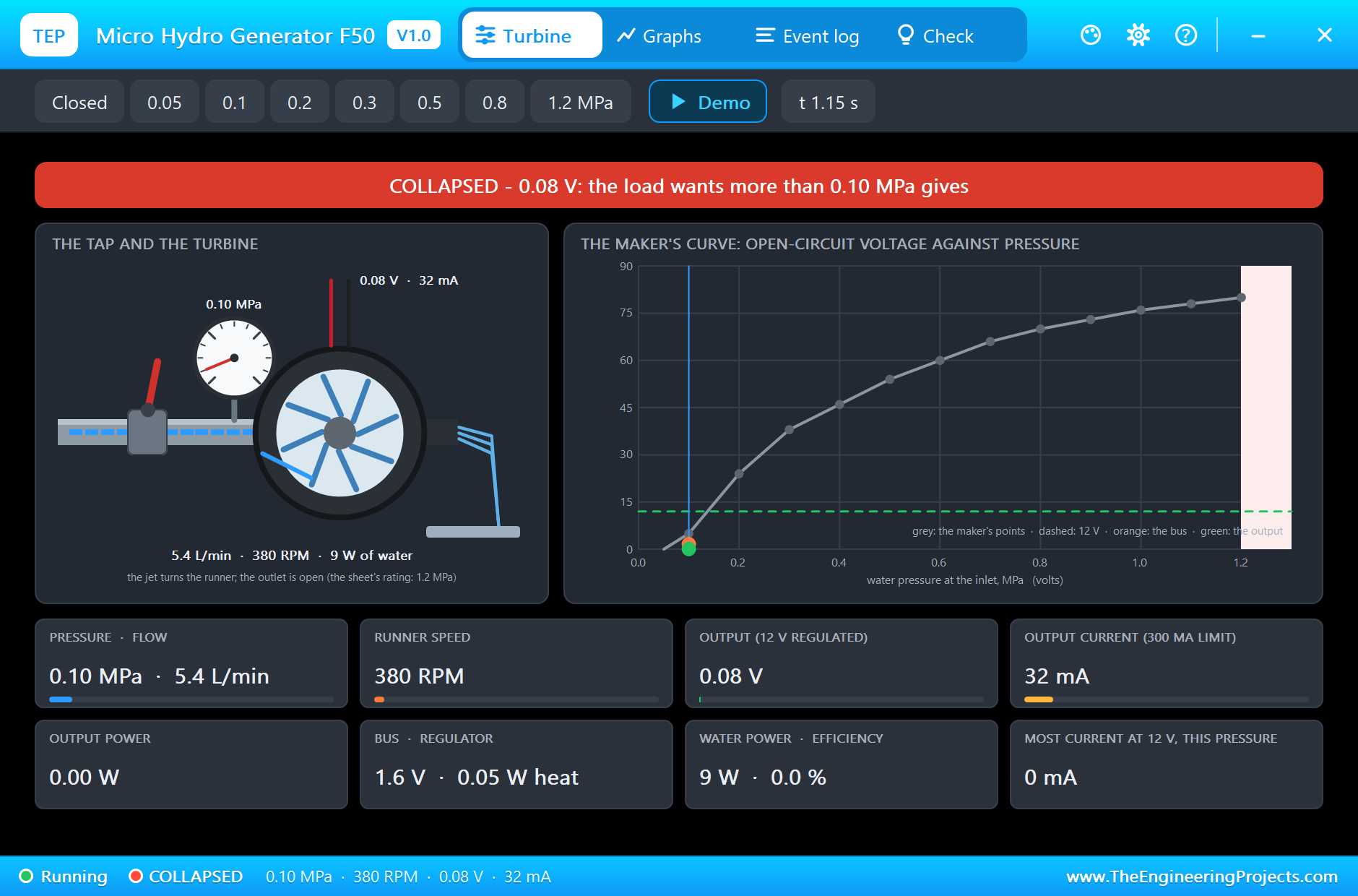
- A pop-up: the tap with its gauge, the turbine through a cut-away, the water leaving it, the maker's curve with the working point, eight live values, graphs, an event log and a check page.
- A complete package: about 1.2 MB with the library, our Arduino UNO V4.0 and the demo, without the source code of the model.
The F50 Micro Hydro Generator in Proteus
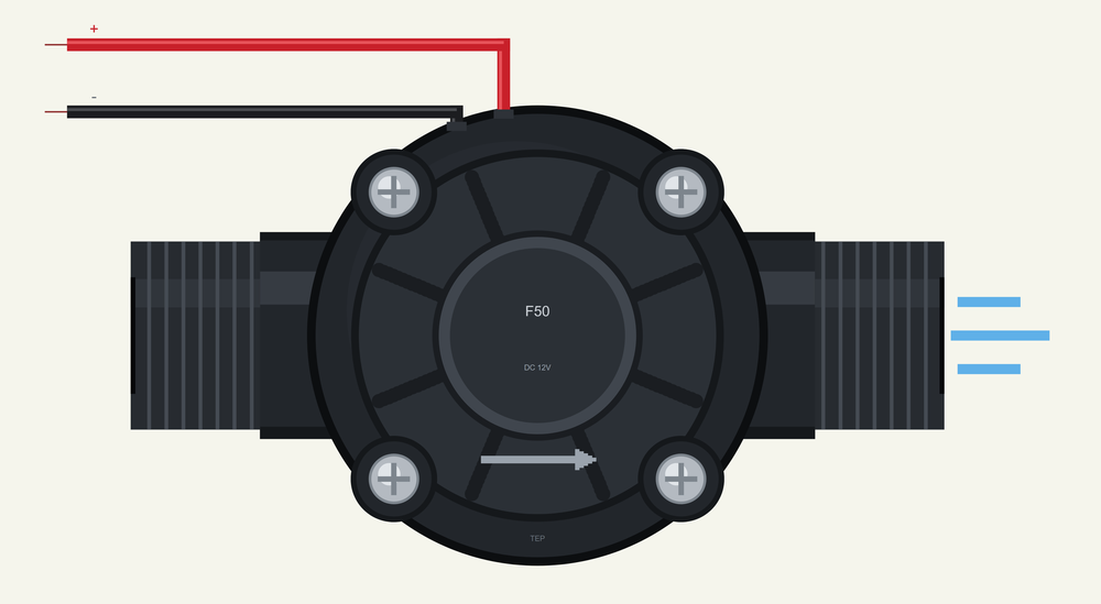
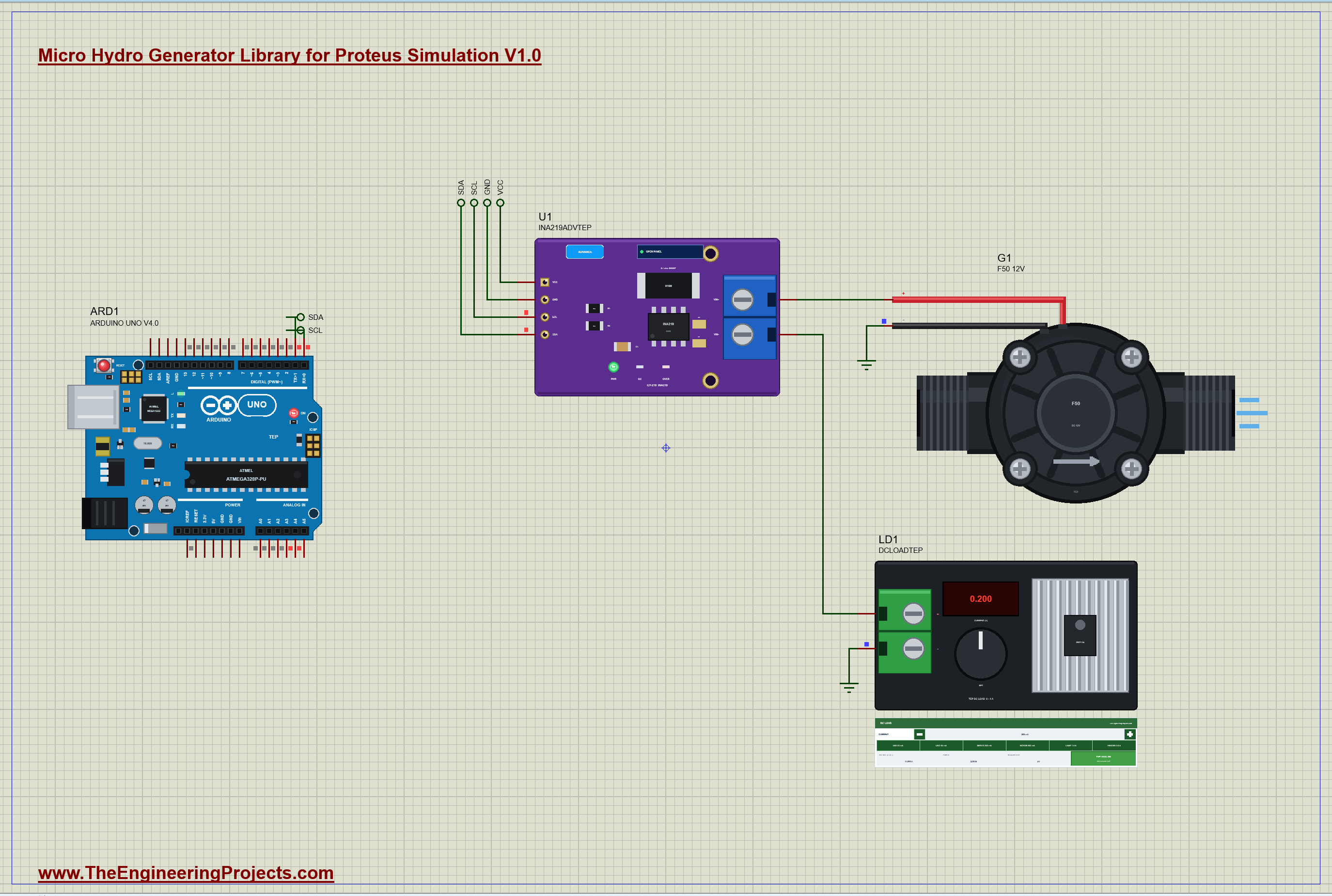
The device is HYDROF50TEP in TEPHYDRO.LIB, under Electromechanical > Generators, with the prefix G and the analog model TEPHYDRO.DLL. Search HYDRO in Pick Devices. Its two pins come out of the top of the body like the real leads: the red + and the black -. The properties are TYPE (12V or 80V) and PRESSURE (MPa at the inlet, or DEMO for the tap profile). The symbol is drawn to the F50's true size against our Arduino UNO, which is why it is a little wider than the board.
Download Micro Hydro Generator Library for Proteus Simulation
Click the button below to download Micro-Hydro-Generator-Library-for-Proteus-v1.0.zip (about 1.2 MB, without the source code of the models):
Micro Hydro Generator Library for Proteus V1.0- README.txt: installation, the demo, the wiring, troubleshooting and the limits of the simulation.
- Proteus Library Files:
TEPHYDRO.LIBandArduinoV4TEP.LIB. - Proteus Model Files:
TEPHYDRO.DLLandTEPARDUINO.DLL. - Arduino Code: the demo sketch.
- Proteus Simulation: the demo project, its HEX file and copies of the DLLs.
No Proteus yet? Read How to Download and Install Proteus 7 and 8. New to libraries? Follow How to Install a New Library in Proteus.
How to Install Micro Hydro Generator Library for Proteus Simulation
- Close Proteus and extract the whole zip file, for example to your Desktop.
- Copy the files from Proteus Library Files into the LIBRARY folder of Proteus.
- Copy the files from Proteus Model Files into the MODELS folder.
- Delete
TEPHYDRO.IDXfrom the LIBRARY folder if it is there. - The demo also uses our INA219 Current Sensor Library for Proteus: install it from its own package (it is not in this zip).
- Start Proteus, press P and search for HYDRO.
Proteus Simulation of the Micro Hydro Generator with Arduino
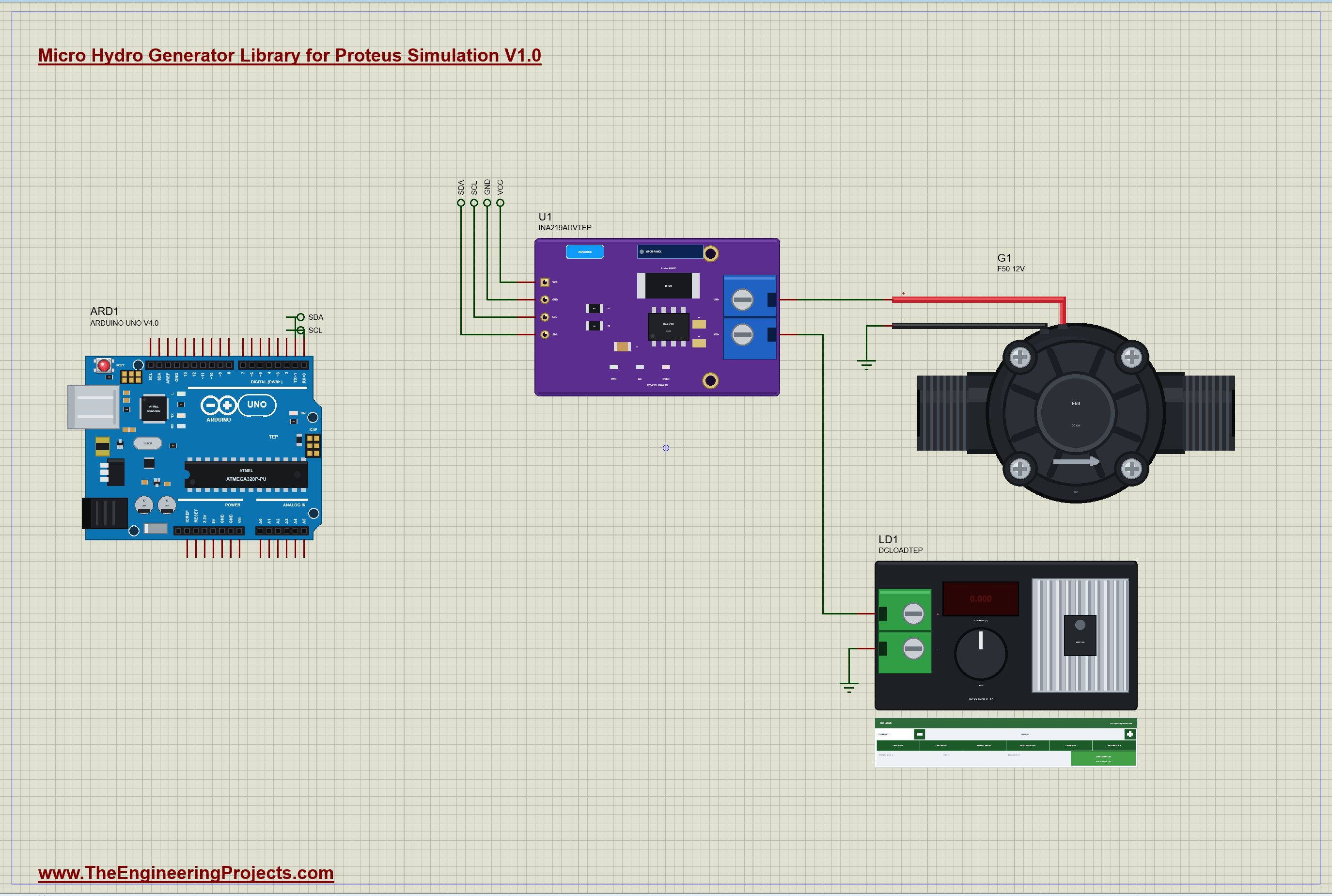
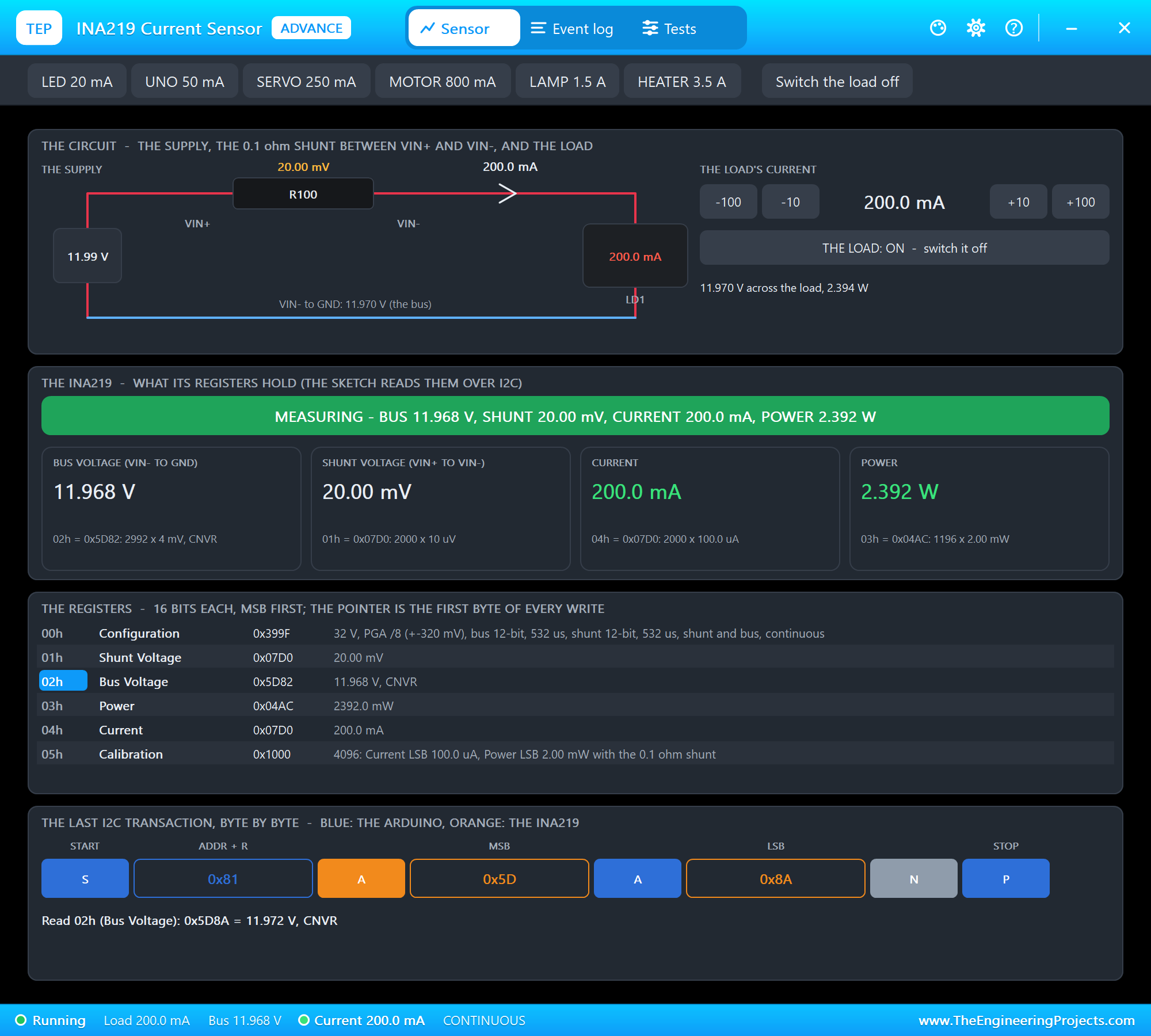
The demo has our Arduino UNO Library for Proteus V4.0 with its built-in monitor, the same window as our TEP Serial Monitor Advance for Proteus, on an A3 sheet. The generator, G1, feeds a load through the 0.1 ohm shunt of our INA219 (U1, its pop-up version), and the load is the DC electronic load of the INA219 library (LD1) set to 200 mA: a 12 V, 2.4 W load such as a small LED lamp. The INA219 talks to the UNO on A4 and A5. G1's PRESSURE is DEMO, so the tap opens by itself: 0.1, 0.2, 0.25, 0.3, 0.5 and 0.8 MPa, one step a second from 0.3 s, then back to 0.3 MPa, and it closes at 7.3 s. Open HYDRO-F50-INA219-ArduinoUnoV4.pdsprj.
The Sketch
The sketch reads the INA219's two voltage registers straight over I2C, with no library: the bus register in 4 mV steps and the shunt register in 10 microvolt steps:
const float shuntV = readReg(0x01) * 0.00001; // 10 uV a stepThe current is the shunt's voltage over its 0.1 ohm, and the generator's own voltage is the bus plus the shunt's drop:
  float amps = shuntV / SHUNT_OHM;
  float volts = bus2 + shuntV;                                   // the generator's own volts
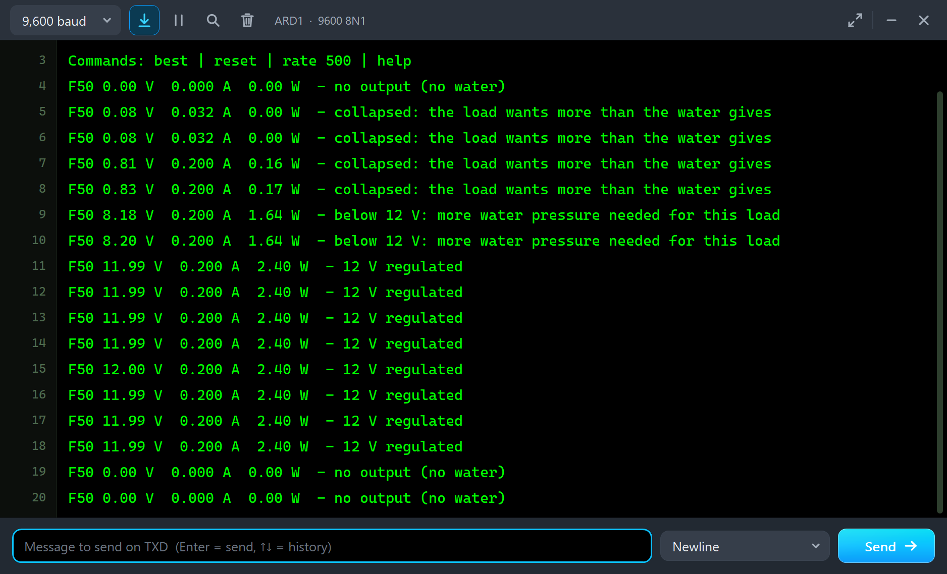
Every half second it prints the volts, amps and watts and says what they mean: 12 V regulated, below 12 V, collapsed or no output. It reads the bus before and after the shunt, so a reading taken while the water changes is marked as changing:
else if (volts >= 11.7 && amps > 0.01) Serial.print(F(" - 12 V regulated"));Afterwards you can type best for the most power seen so far, reset to forget it, or rate 1000 to report once a second.
Micro Hydro Generator Simulation Results
Open the project and press Run. The demo runs about 8 simulated seconds; with the pop-up open and the pictures being taken it took about two minutes on our PC. Click the generator for its pop-up. Every number below comes from one simulation run, the demo exactly as it ships.
Too Little Water: 0.1 and 0.2 MPa
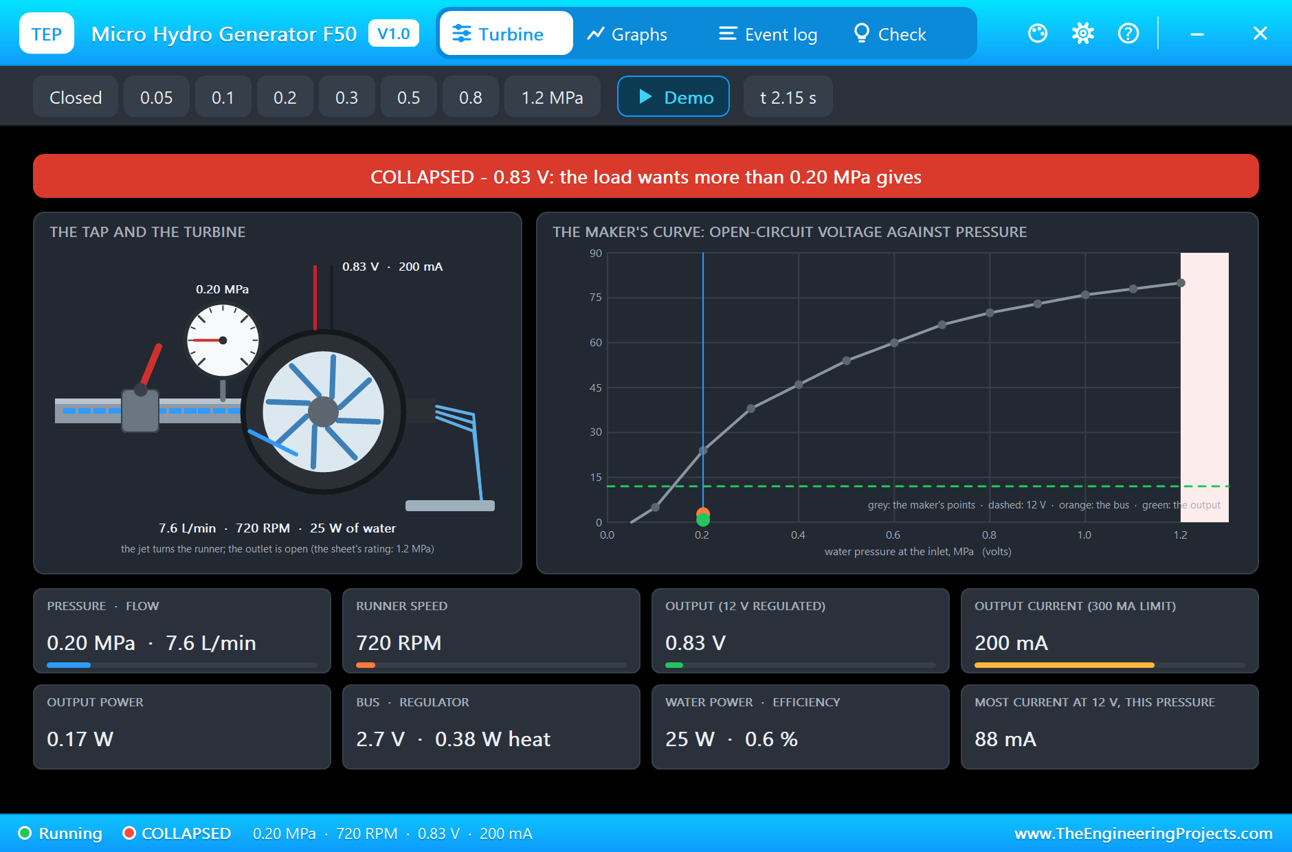
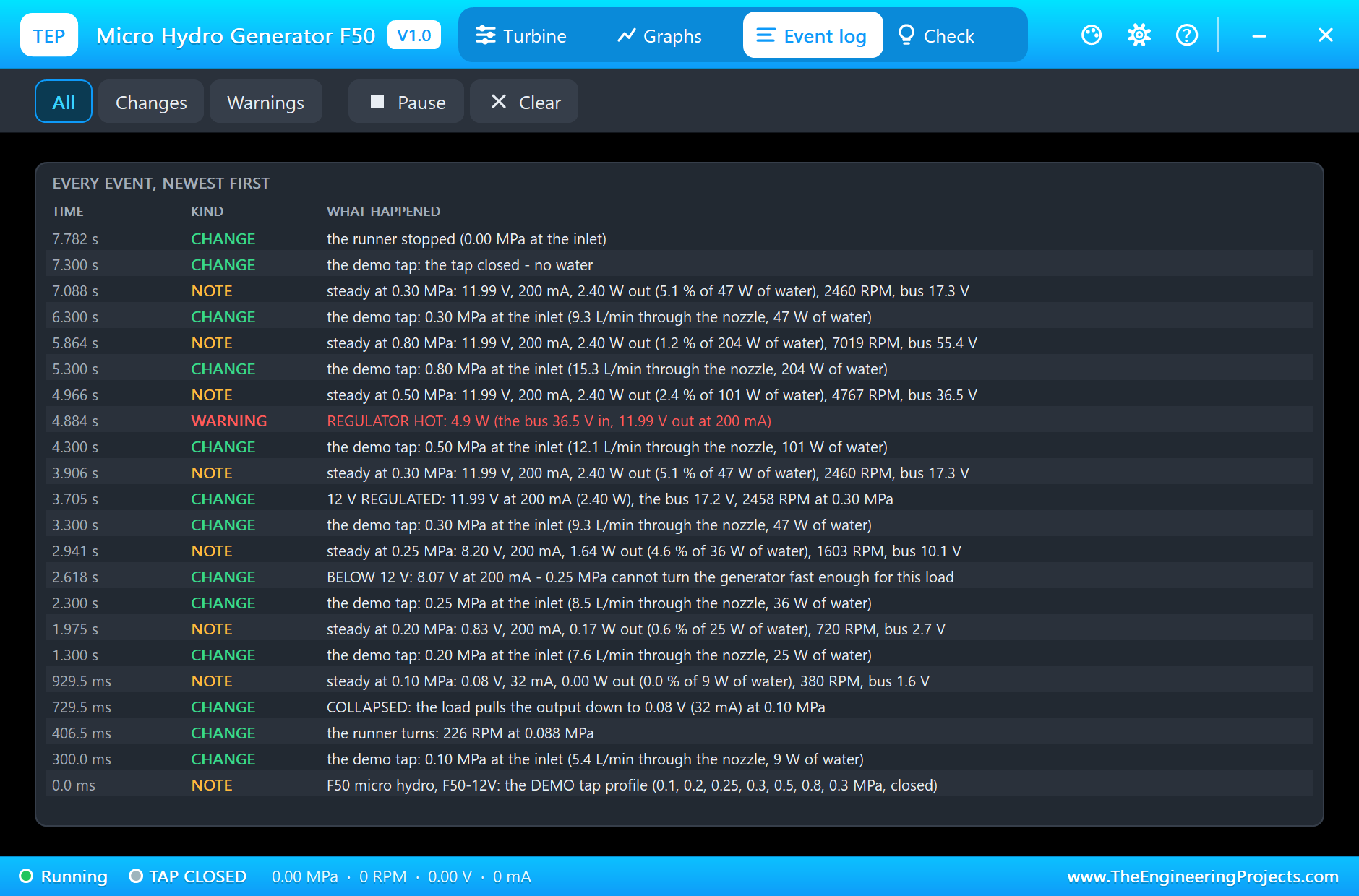
At 0.3 s the tap opens to 0.1 MPa and 5.4 litres a minute run through the nozzle, about 9 W of water. The runner starts as soon as the pressure passes 0.05 MPa and settles at 380 RPM. But a 200 mA load is far too much for so little water: the output collapses to 0.08 V, and only 32 mA flows. At 0.2 MPa the runner reaches 720 RPM and the load gets its 200 mA, but at only 0.83 V, the bus at 2.7 V. The last tile says why: at this pressure the water could hold 12 V for 88 mA at most.
Almost There: 0.25 MPa
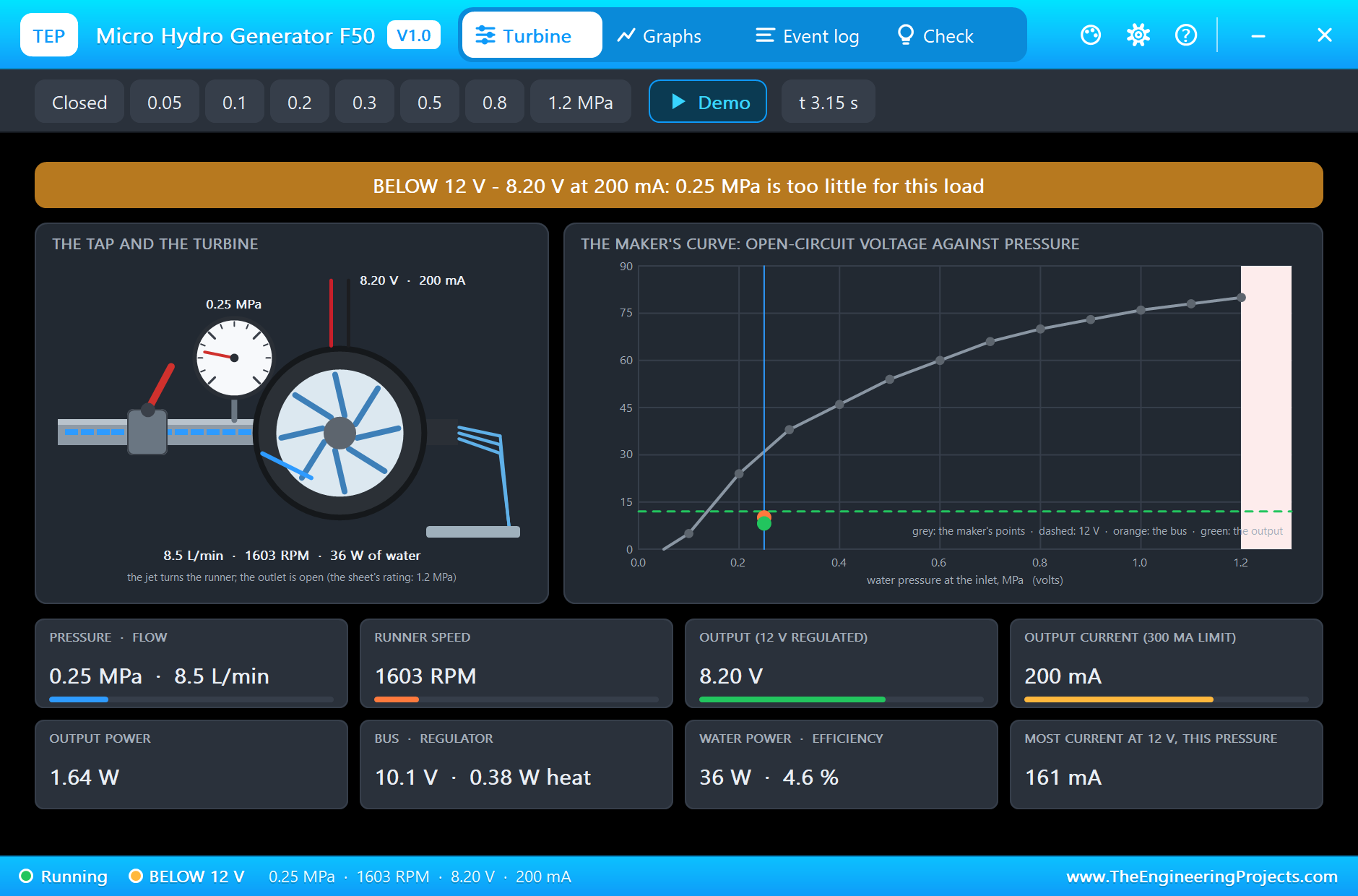
At 0.25 MPa (8.5 litres a minute) the runner turns at 1,603 RPM and the output rises to 8.20 V at 200 mA, 4.6 % of the 36 W of water. The banner says BELOW 12 V: the bus is 10.1 V, under the 13.5 V the regulator needs, so the regulator simply passes what it gets. The most current at 12 V has grown to 161 mA, still short of the load's 200.
12 V Regulated: 0.3 MPa
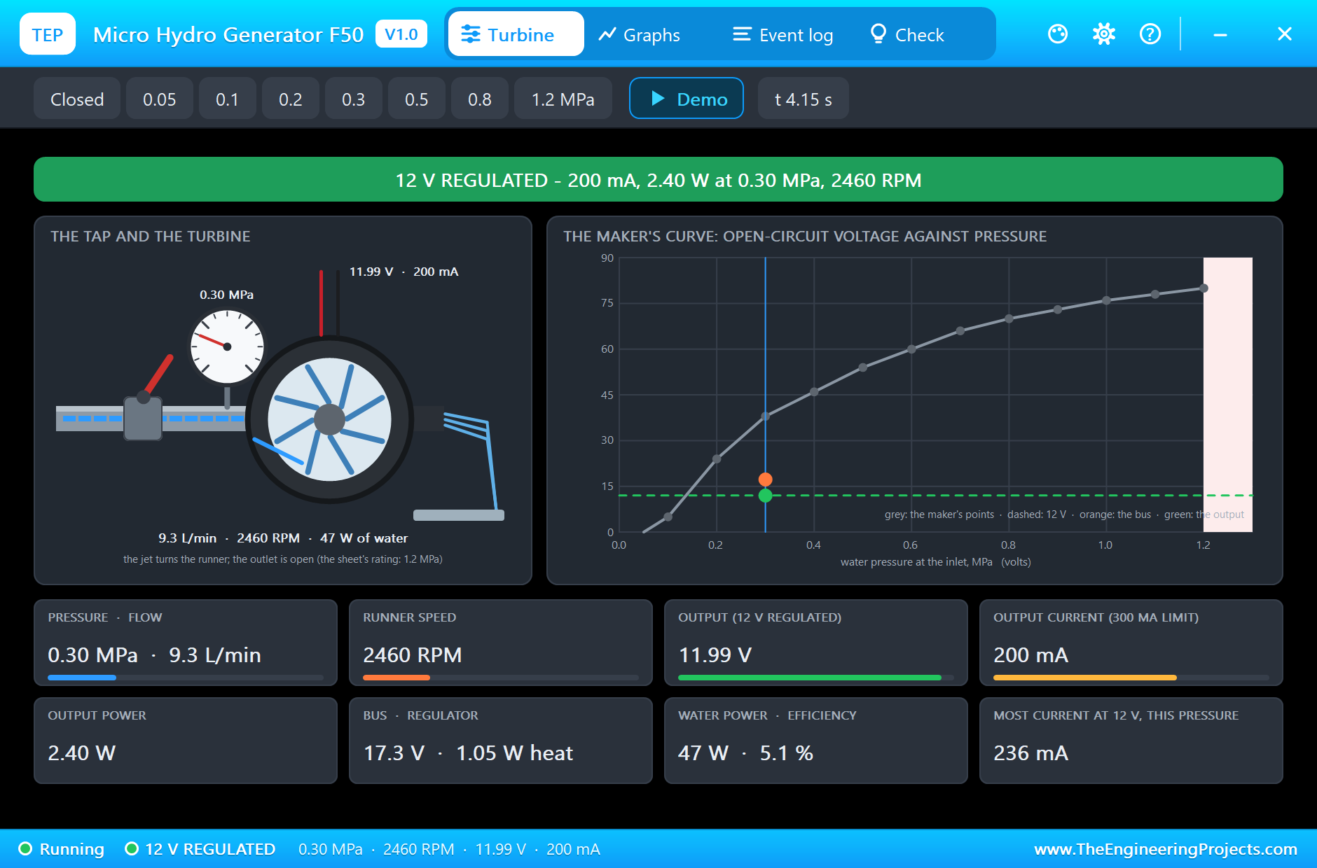
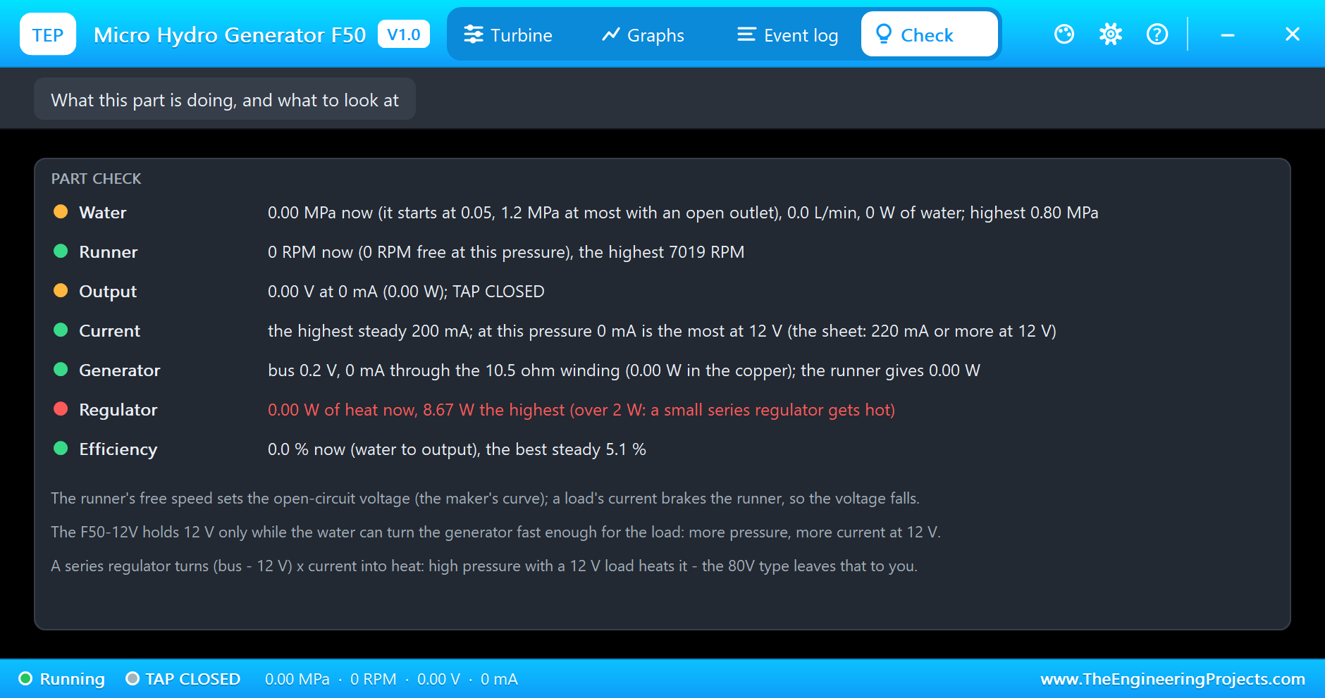
At 3.3 s the tap opens to 0.3 MPa, a normal household pressure. At 3.705 s the Event log records 12 V REGULATED, and a moment later the simulation settles: 11.99 V at 200 mA, 2.40 W, the runner at 2,460 RPM and the bus at 17.3 V. The regulator turns the difference into 1.05 W of heat. The water brings 47 W (9.3 litres a minute), so the whole machine is 5.1 % efficient, normal for a turbine this small. And the last tile answers the F50's own rating: at 0.3 MPa the water can hold 12 V for up to 236 mA, a little more than the 220 mA on the maker's sheet.
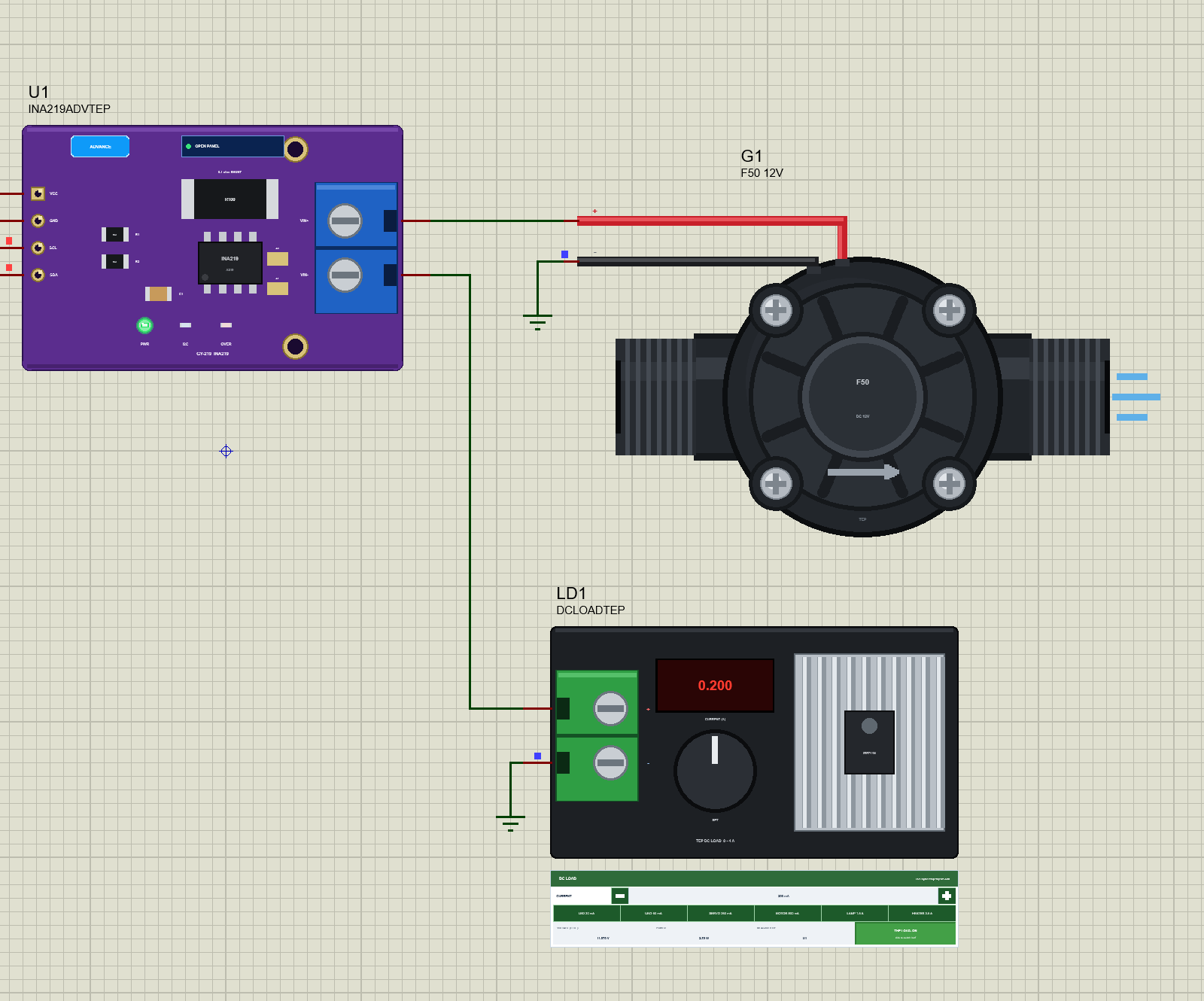
The INA219's own pop-up agrees: 11.99 V at the supply, 20.00 mV across the 0.1 ohm shunt, 11.968 V on the bus after it, 200.0 mA and 2.392 W, read from its registers by the sketch over I2C.
More Pressure, More Heat: 0.5 and 0.8 MPa
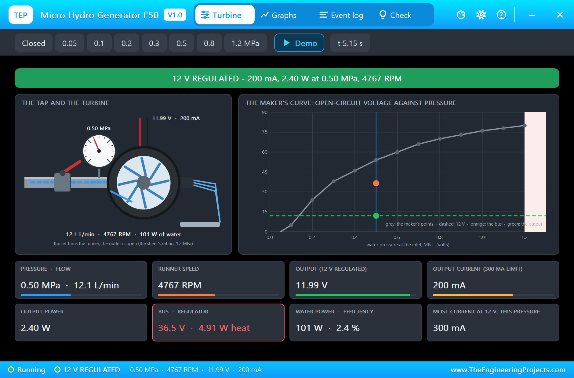
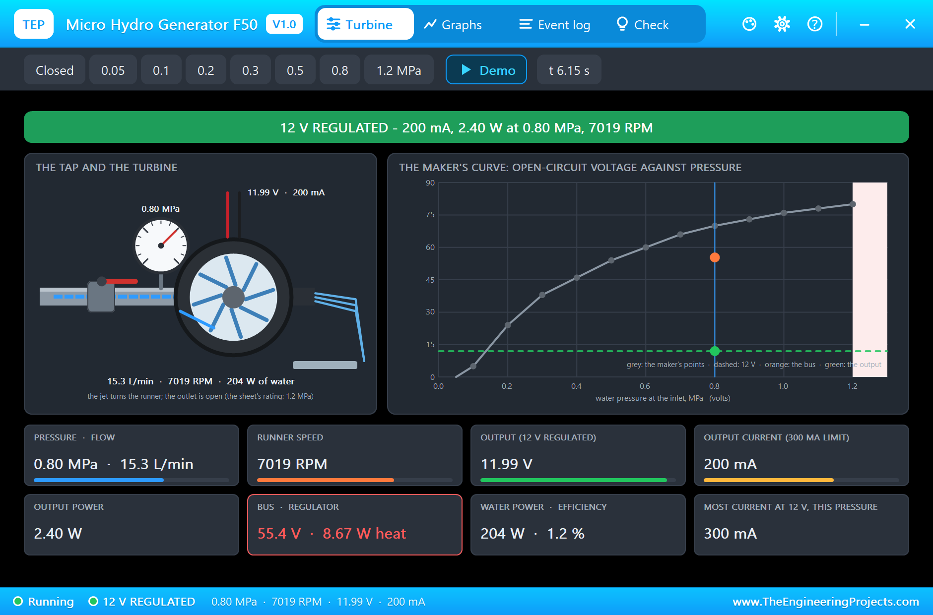
At 0.5 MPa the output stays at 12 V, but everything behind it changes. The runner speeds up to 4,767 RPM, the bus rises to 36.5 V, and the regulator now burns 4.91 W to give the same 2.40 W. At 4.884 s the Event log warns REGULATOR HOT. At 0.8 MPa the runner turns at 7,019 RPM, the bus stands at 55.4 V and the regulator takes 8.67 W, while 204 W of water rush through. The efficiency falls to 1.2 %: a 12 V load does not need high pressure, and this simulation shows exactly why.
Back at 0.3 MPa the simulation returns to exactly the same point: 11.99 V at 200 mA, 2,460 RPM, the bus at 17.3 V. At 7.3 s the tap closes, the runner coasts down and stops at 7.782 s, and the output falls to zero.
The Graphs, the Event Log and the Check Page
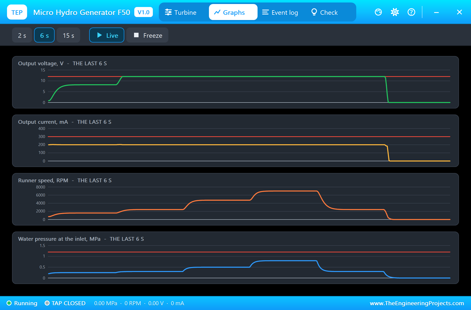
The Graphs page plots the output voltage, the output current, the runner's speed and the water pressure over the last 2, 6 or 15 simulated seconds: the steps of the tap, the speed climbing with each one, and the output pinned at 12 V from 0.3 MPa up. The Event log keeps every tap step, every change of state, a steady point for each pressure with its efficiency, and the warnings. The Check page sums up the water, the runner, the output, the current, the generator, the regulator and the efficiency.
Try It Yourself
- Raise the DC load to 250 mA on the INA219's pop-up: at 0.3 MPa the output falls below 12 V (236 mA is the most), at 0.5 MPa it holds.
- Set TYPE to 80V and PRESSURE to 0.3: no regulator, and the output follows the generator's load line.
- Lower the DC load to 100 mA and step the tap again: 12 V now holds from a lower pressure.
- Close the tap from the pop-up while the load runs and watch the runner coast down on the Graphs page.
Ideas to Extend the Demo
- Charge a 12 V battery through a charge controller and log the energy over a day of changing pressure.
- Add a pressure sensor and let the sketch estimate the water flow from the generator's voltage.
- Switch loads on and off with a relay so the generator always works near its best current.
Your Own Sketches
The demo sketch is in the zip file, and you can change it in the Arduino IDE. New to Arduino? Start with our Arduino Tutorial for Beginners. Export the compiled binary, and set the UNO's PROGRAM property to the new file. Our guide on How to get the HEX file from Arduino shows you where the file ends up.
Things to Know Before Using a Real F50
- Mind the arrow: the water must flow the way the arrow on the body points; use thread tape on both threads.
- Keep the outlet open: the sheet allows 0.6 MPa with the outlet closed and 1.2 MPa with it open.
- Match the load to the water: measure your pressure first; at 0.2 MPa expect well under 100 mA at 12 V.
- High pressure costs heat: with a 12 V load, more pressure only warms the regulator; the F50-80V with your own converter wastes less.
Troubleshooting
- Nothing at the output: the pressure is under 0.05 MPa or the tap is closed in the pop-up.
- BELOW 12 V: the load wants more current than the water gives at this pressure; open the tap or take less current.
- REGULATOR HOT: a high pressure with a 12 V load; use less pressure.
- OVER PRESSURE: more than 1.2 MPa, the F50's rating with an open outlet.
- The part is not simulated:
TEPHYDRO.DLLis missing from MODELS and from the project folder.
Limitations of the Simulation
- The open-circuit voltage follows the maker's twelve points with straight lines between them; the stall torque, the generator constant, the inertia, the nozzle and the regulator are our figures.
- The rectifier's ripple is not modelled: the generator gives its DC average.
- The flow is the open outlet's; a throttled outlet, water hammer and the regulator's own temperature are not modelled (its heat is shown, not a shutdown).
- Arduino is a name of Arduino; this library is not made or endorsed by Arduino, Labcenter or any turbine maker.
- Tested in Proteus 8.5 in November 2026 (the demo as shipped). Proteus 7 is not supported.
So, that was all about the Micro Hydro Generator Library for Proteus Simulation. I hope it helps you try a water-powered project in a simulation before you plumb in the real F50: the maker's curve, a runner that slows under load, a 12 V regulator that holds only while the water allows, and a pop-up that shows the tap, the turbine and every number in between. If you have any questions, ask in the comments and I will help you out. Till the next tutorial, take care and have fun!