Hello friends, I hope you all are doing great. Today, I am going to share the IoT Split-Flap Message Board with Raspberry Pi 5 - Proteus Simulation, the thirty-fourth project of our IoT Projects series. If you have searched for a Proteus simulation of a Raspberry Pi split-flap display, the clattering flaps of old railway and airport departure boards, here is a complete one. A Raspberry Pi 5 drives four split-flap modules through four ULN2003 boards, finds each module's home with its hall sensor, steps all four from one Python thread, shows words and the time, and serves a live web dashboard that you can open on a laptop or a phone.
A split-flap module is a lovely piece of mechanics: a spool of 40 printed flaps, a small stepper motor and a magnet. It only turns forwards, it has no idea where it is when it powers up, and every flap that falls adds a little load to the motor. In this tutorial, we will go through the circuit, learn how a split-flap module and its 28BYJ-48 stepper work, drive the stepper through a ULN2003 with half steps, find home with a hall sensor and keep the position right with every turn, step four motors at once from one thread with their own speed ramps, walk through the Python program, and then run the simulation: homing, OPEN, BUSY, FREE, a clock and homing again. At the end, you can download the project with the program, every library file and the Python runtime the Pi needs.
NOTICE: Our team has put a lot of effort into this project: the circuit, the code and every part in the simulation are our own work, and you get them all free. Your feedback is the fuel that keeps us going, so please tell us what you think in the comments below. And if our free projects help you, you can buy us a coffee. So, let's get started with the IoT Split-Flap Message Board with Raspberry Pi 5 - Proteus Simulation:
What Does This Split-Flap Board Do?
- Four characters: four split-flap modules, each with 40 flaps: blank, A to Z, 0 to 9, a full stop, a dash and a question mark.
- Finds home: at power-up each module turns until its hall sensor sees the magnet, then it knows where it is.
- Never drifts: every time the magnet passes, the position is set again.
- Four motors, one thread: all four step at once, each on its own clock with a speed ramp.
- Words and a clock: OPEN, BUSY and FREE, or the time as four digits, new every minute.
- Saves power: the coils switch off 150 ms after a stop; the gearbox holds the spool.
- A dashboard: the controls, what the board shows and the home passes, from a laptop or a phone.
It is a great project for learning how to drive stepper motors, why homing matters, and how to share time between several jobs in one program. In the simulation, every module's pop-up shows its spool turning, the falling flap and the motor's coils.
Components Used in the Proteus Simulation
All the parts come from our Proteus libraries, each with its own tutorial. The project zip at the end includes every LIB and DLL file.
| Part | Proteus device | Library post | Connection |
|---|---|---|---|
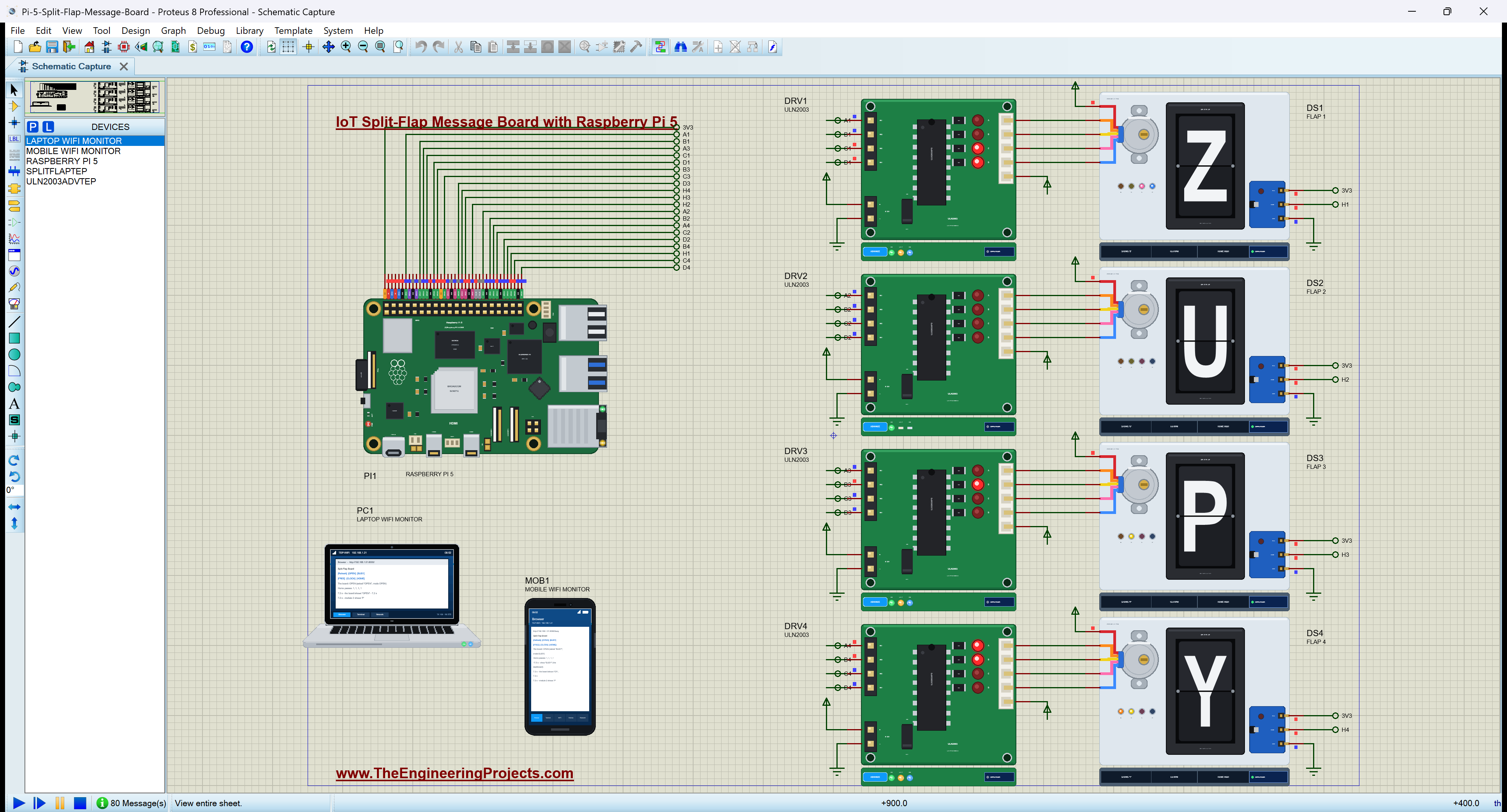
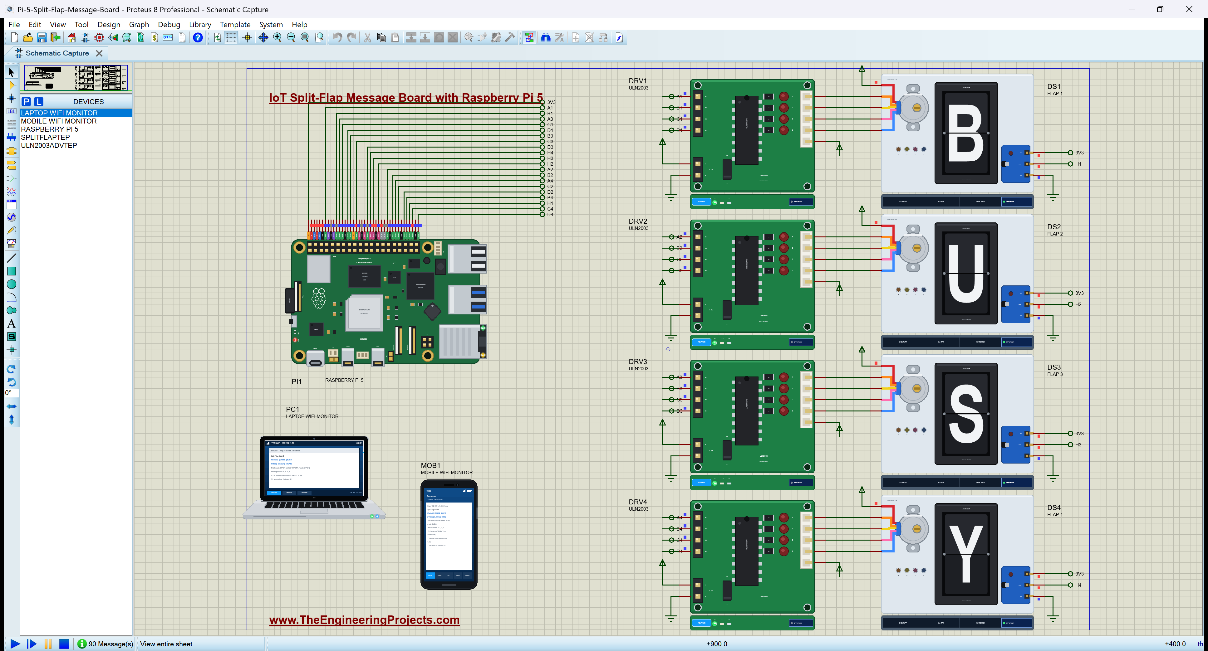
| Raspberry Pi 5 | RASPBERRY PI 5 | Raspberry Pi 5 Library for Proteus | PI1, Ethernet 192.168.1.51 |
| Split-flap module x 4 (28BYJ-48, hall sensor) | SPLITFLAPTEP | Split-Flap Display Library for Proteus | DS1 - DS4 |
| ULN2003 driver board x 4 | ULN2003ADVTEP | 28BYJ-48 and ULN2003 Stepper Library for Proteus | DRV1 - DRV4 |
| Laptop WiFi Monitor | LAPTOP WIFI MONITOR | Laptop WiFi Monitor | PC1 |
| Mobile WiFi Monitor | MOBILE WIFI MONITOR | Mobile WiFi Monitor | MOB1 |
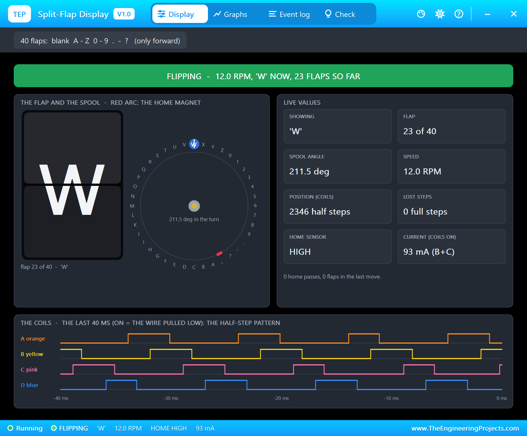
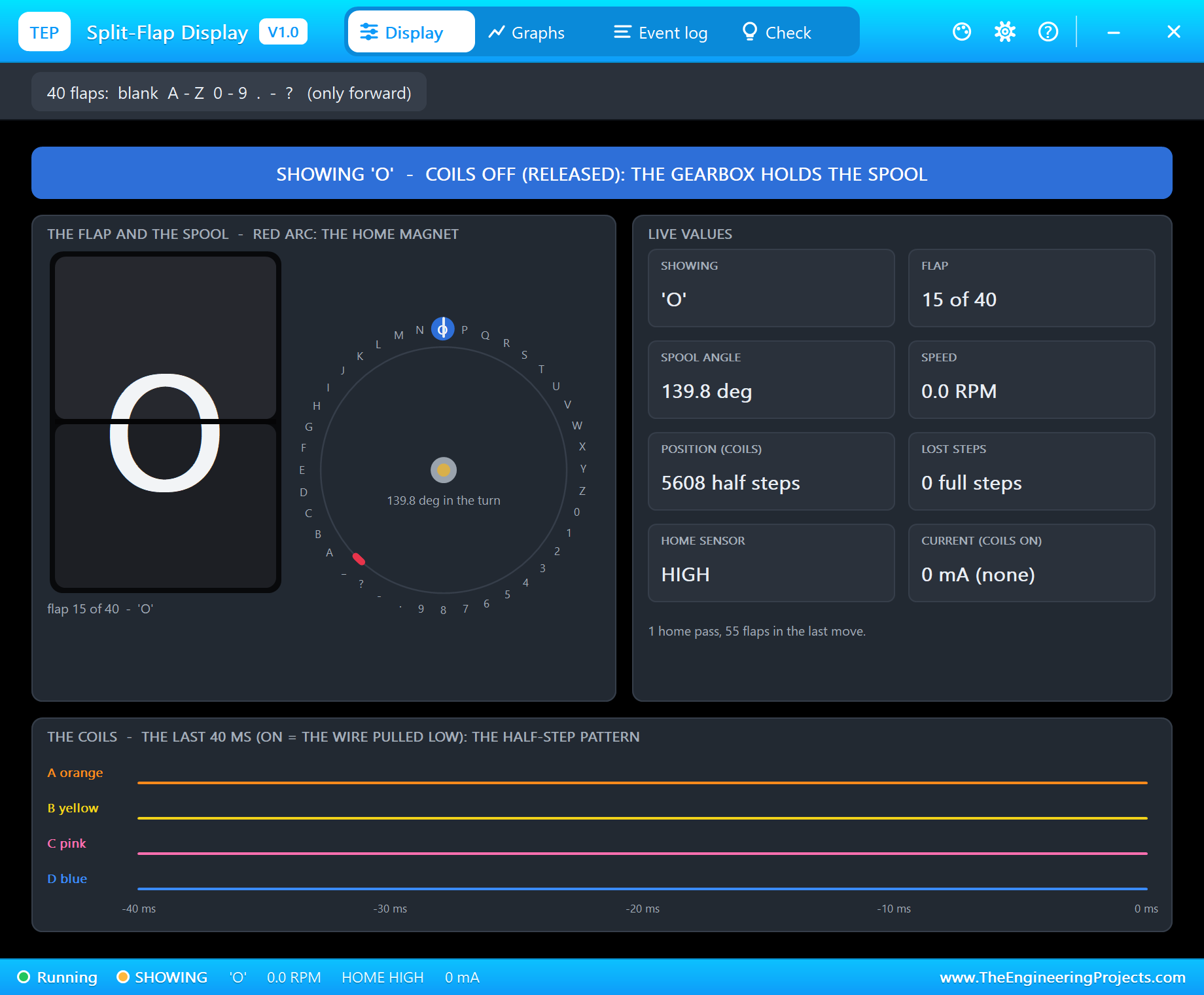
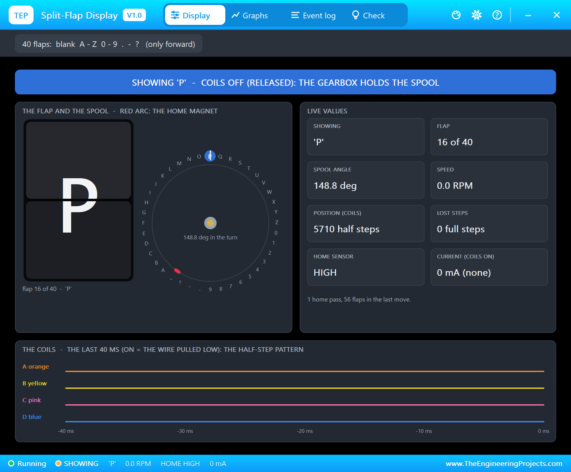
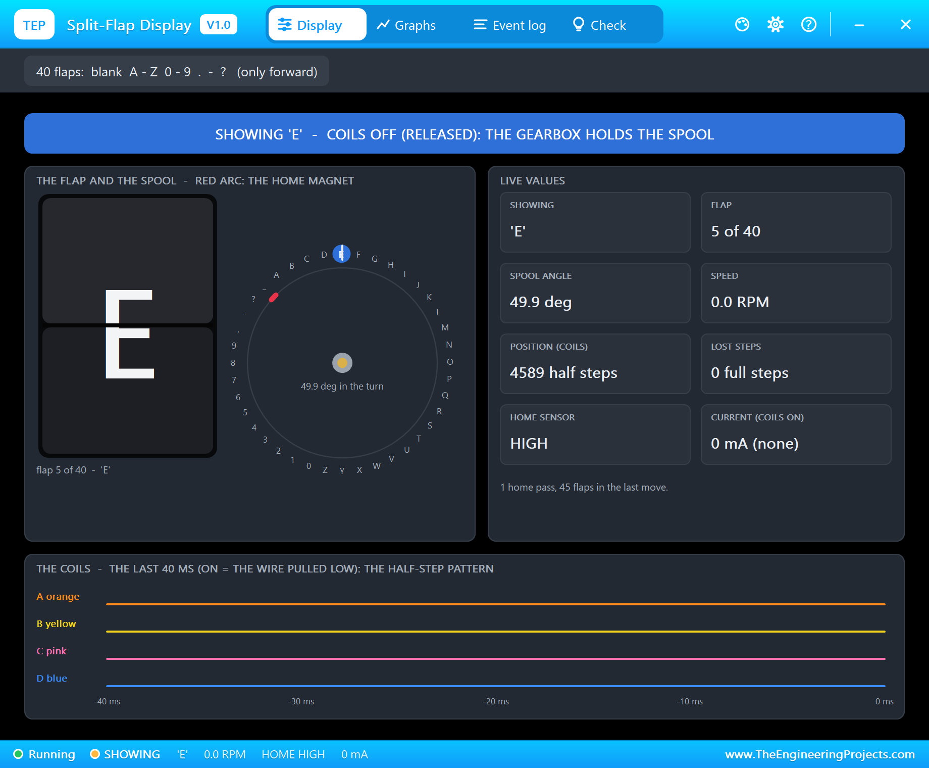
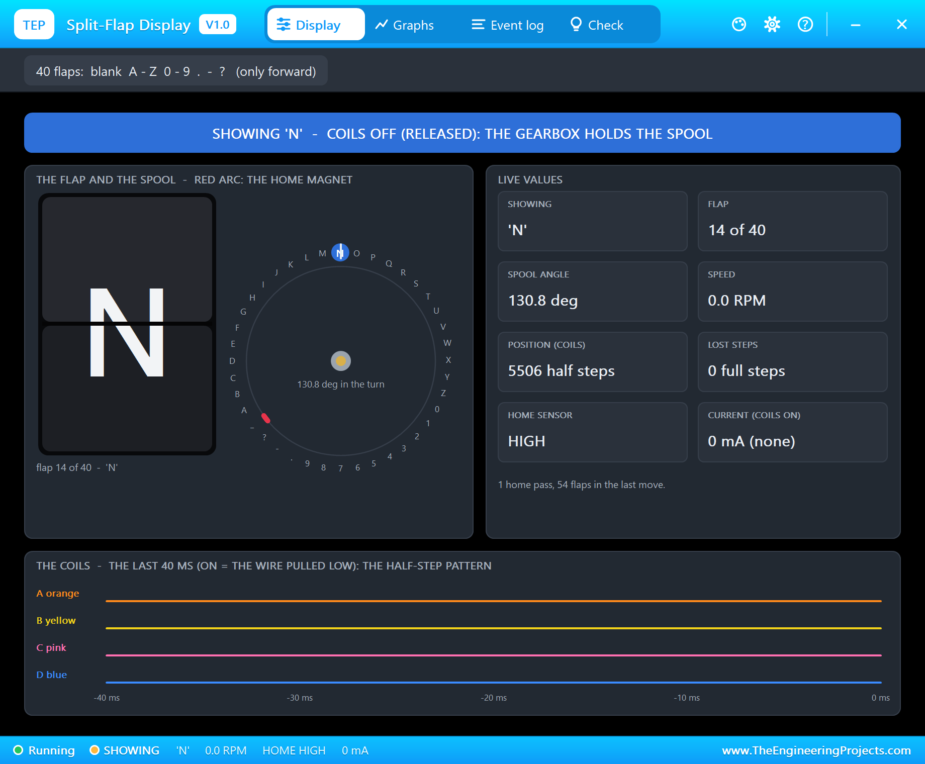
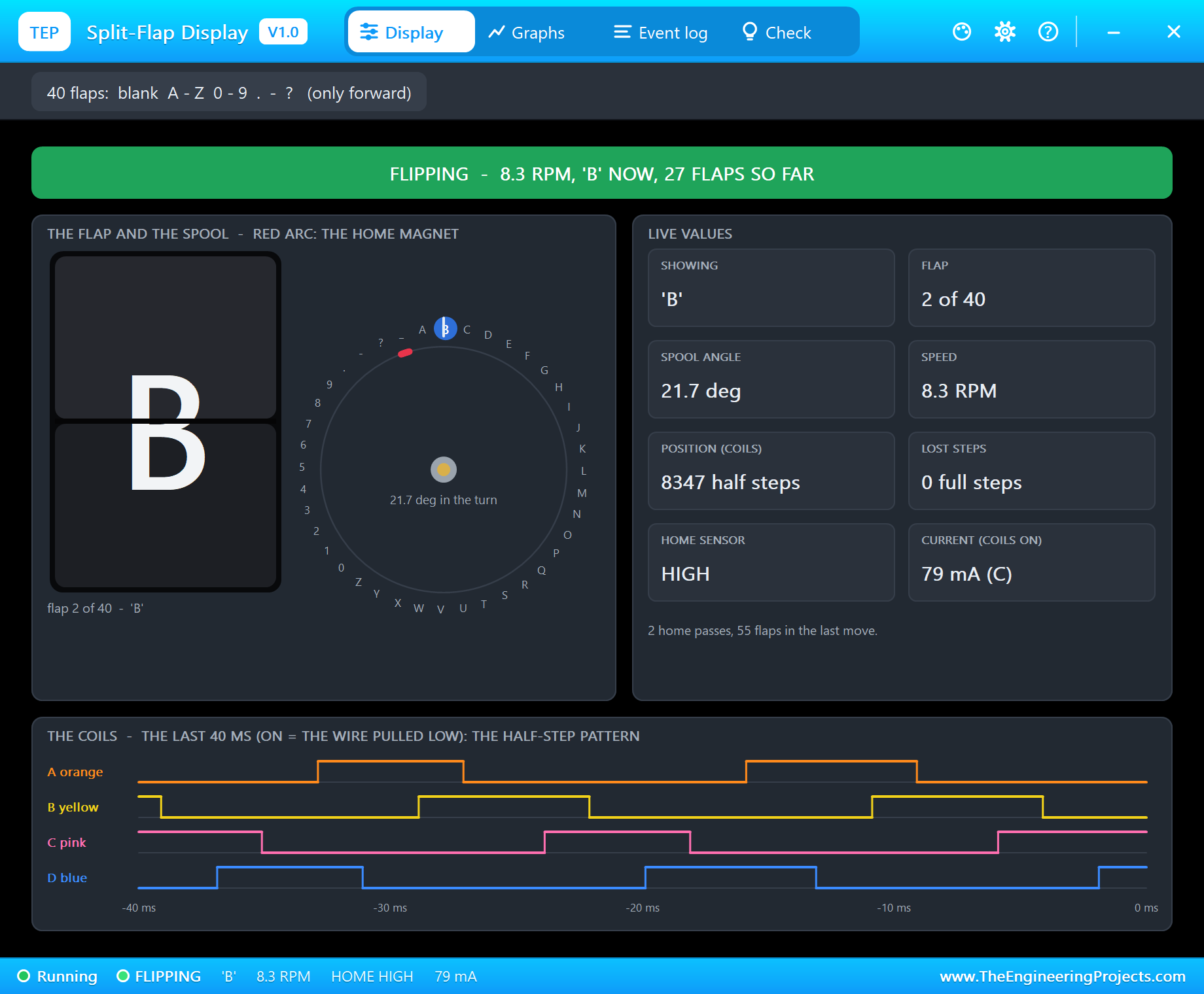
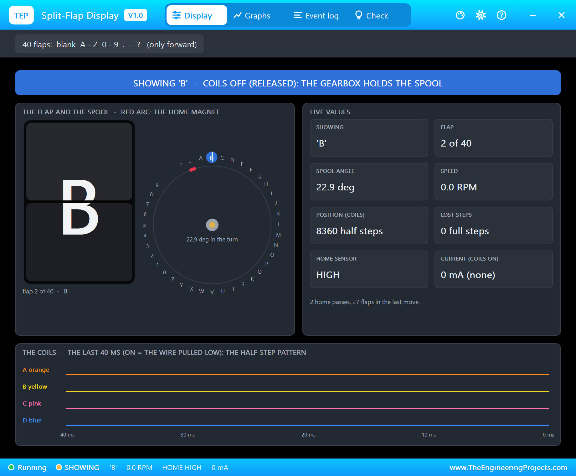
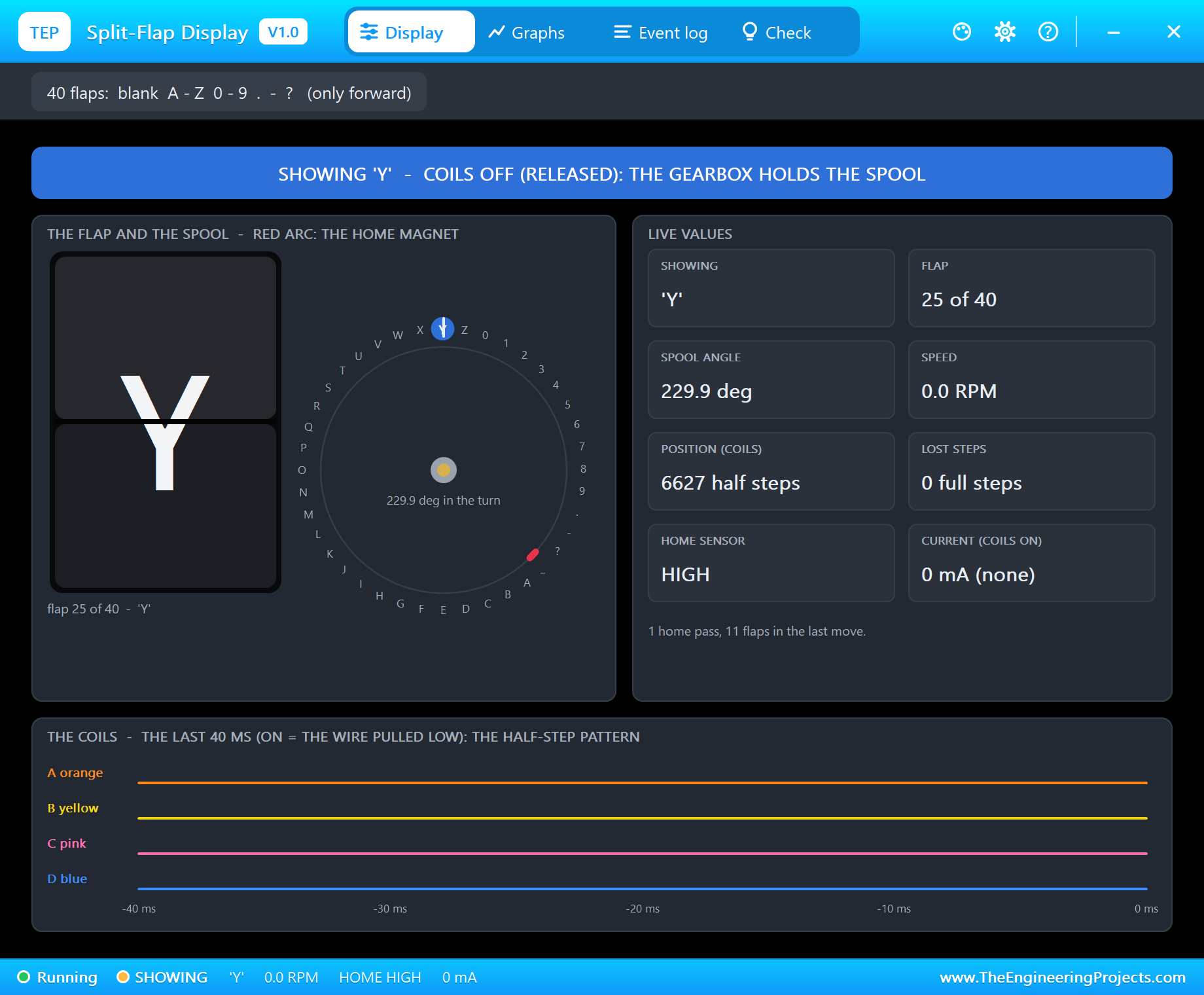
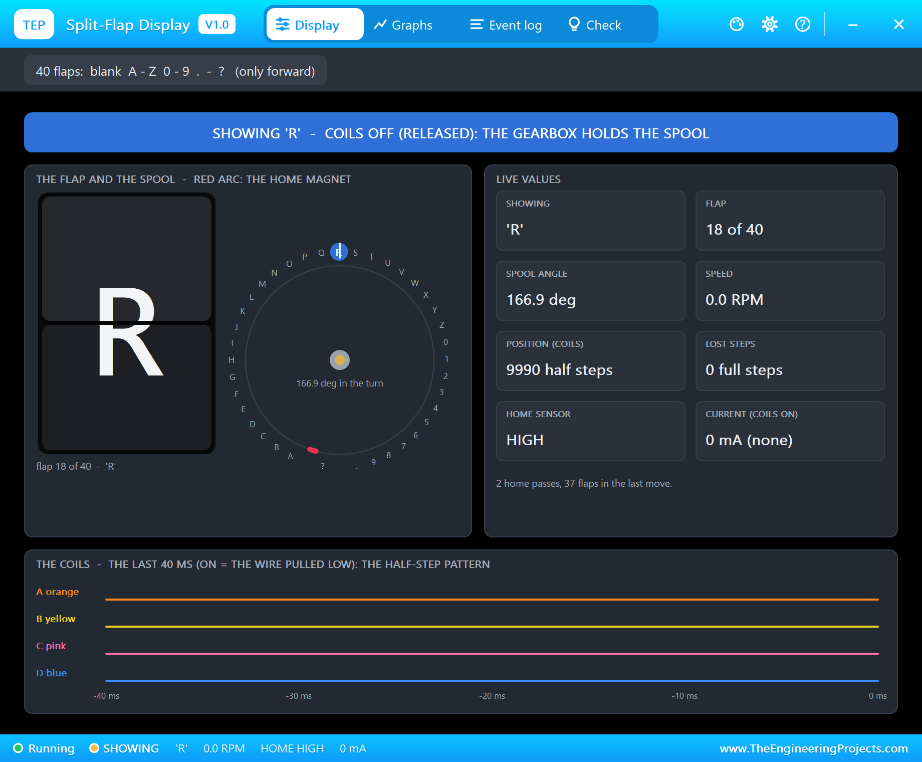
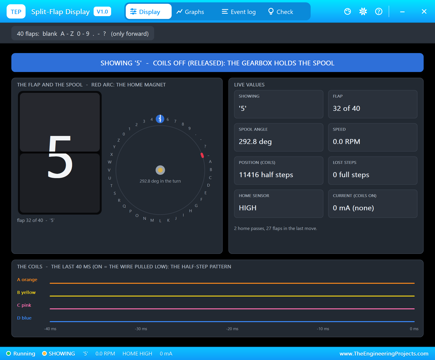
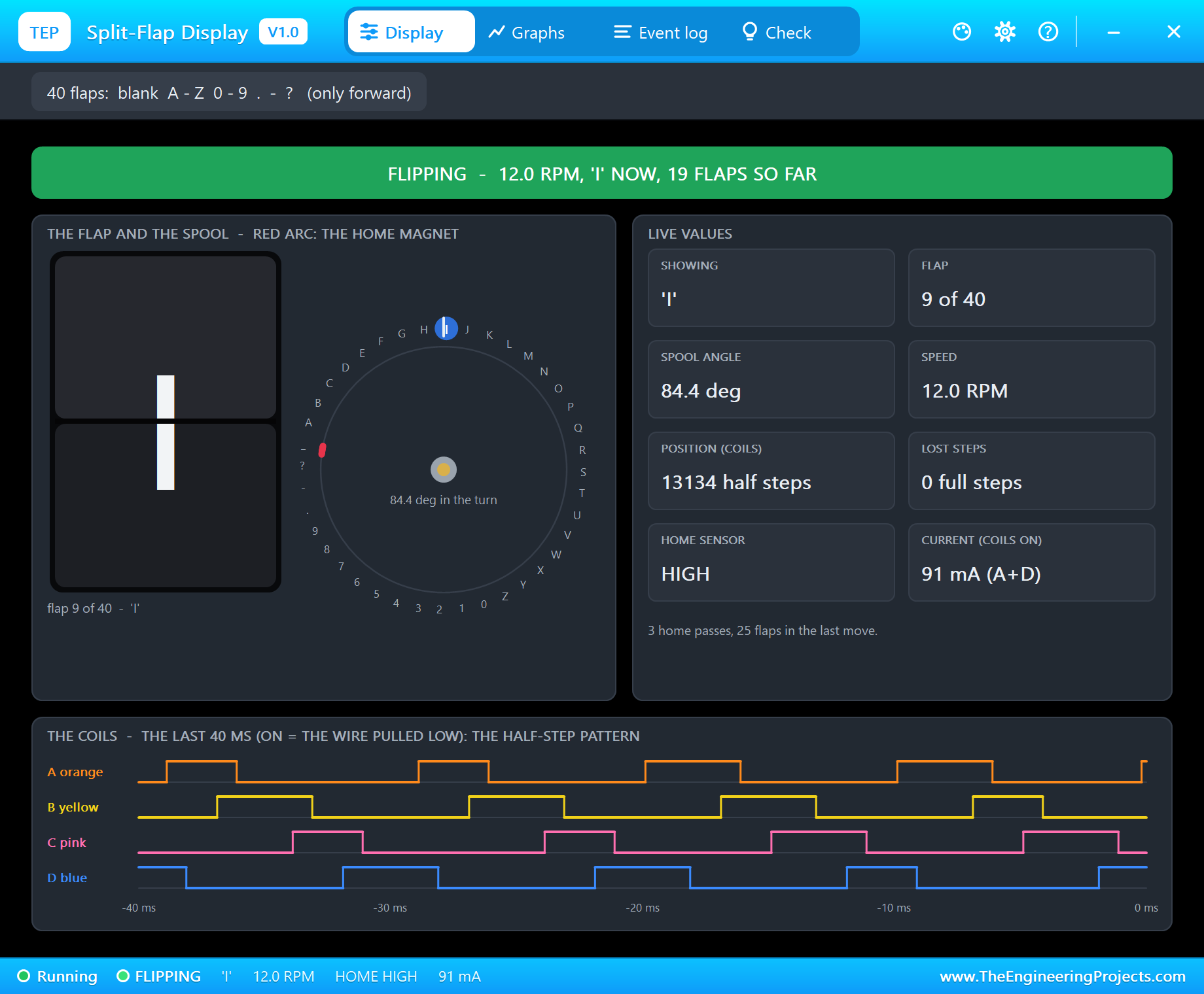
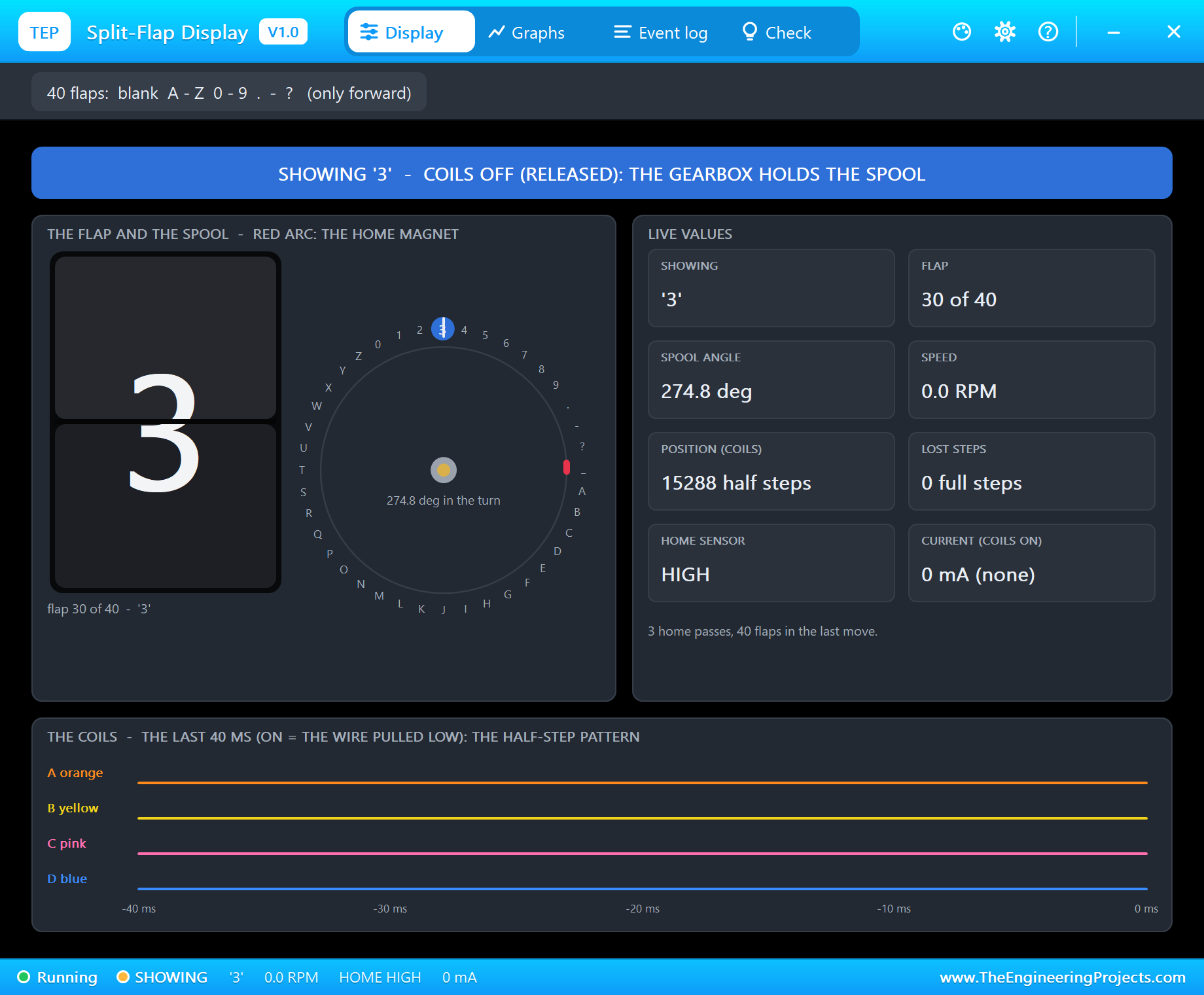
The split-flap modules and the ULN2003 boards are models with pop-ups. A module's pop-up shows the flap in its window, the spool's 40 flaps in a ring with the home magnet marked, the spool's angle and speed, the coils' half-step pattern, the home sensor and any lost steps. The ULN2003's pop-up shows its four channels and the motor's steps.
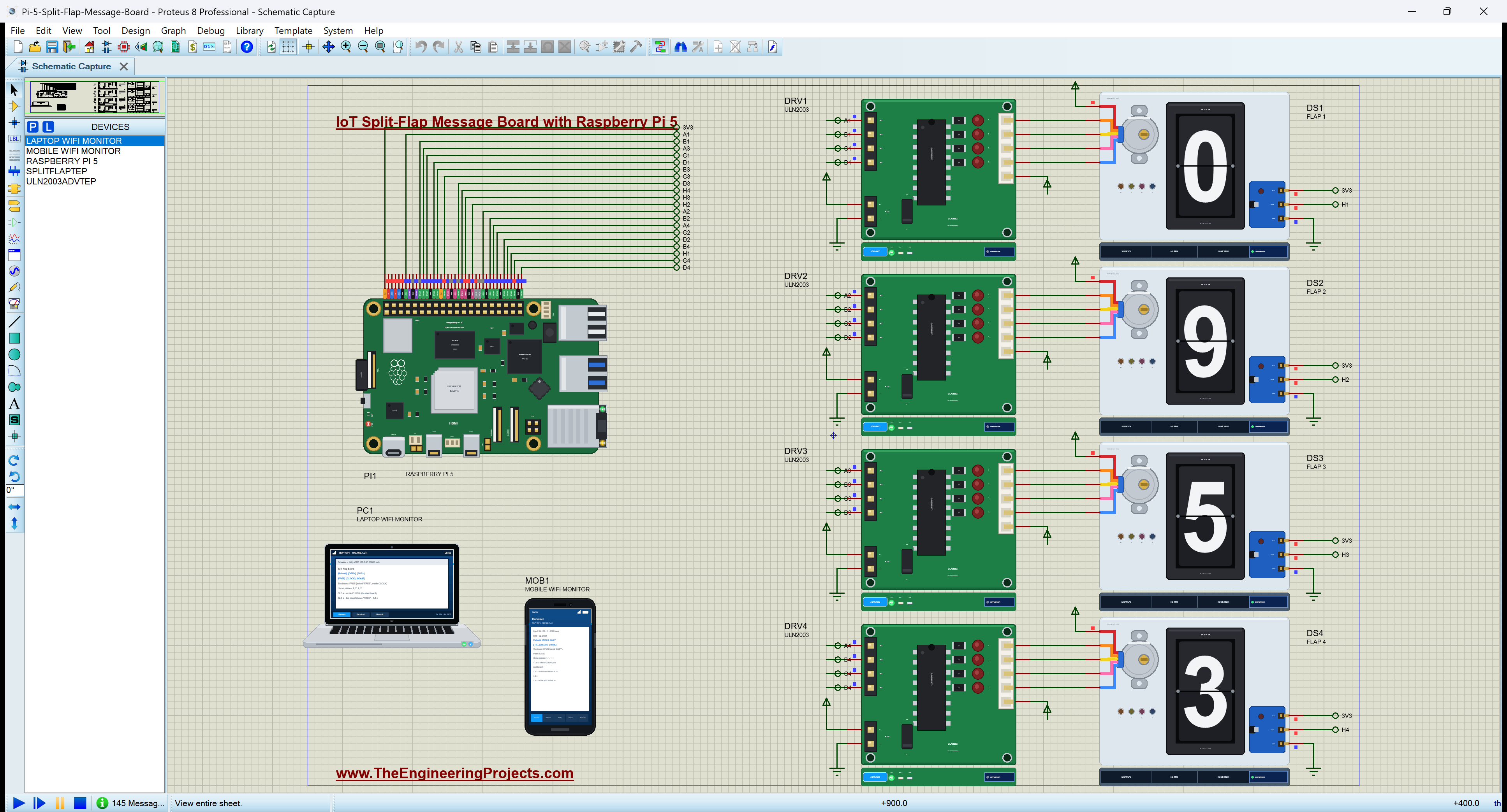
Proteus Simulation of the Split-Flap Board: the Circuit
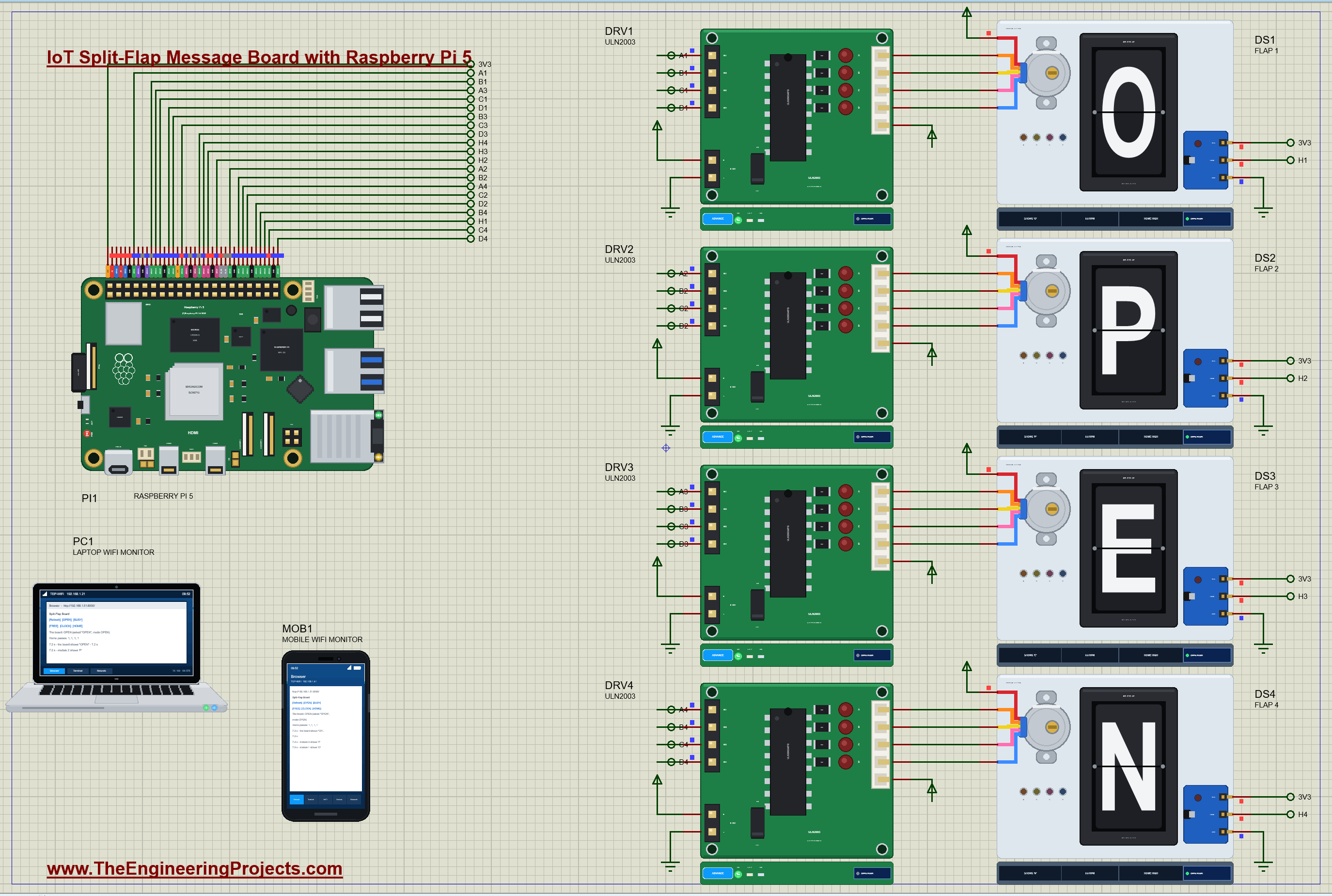
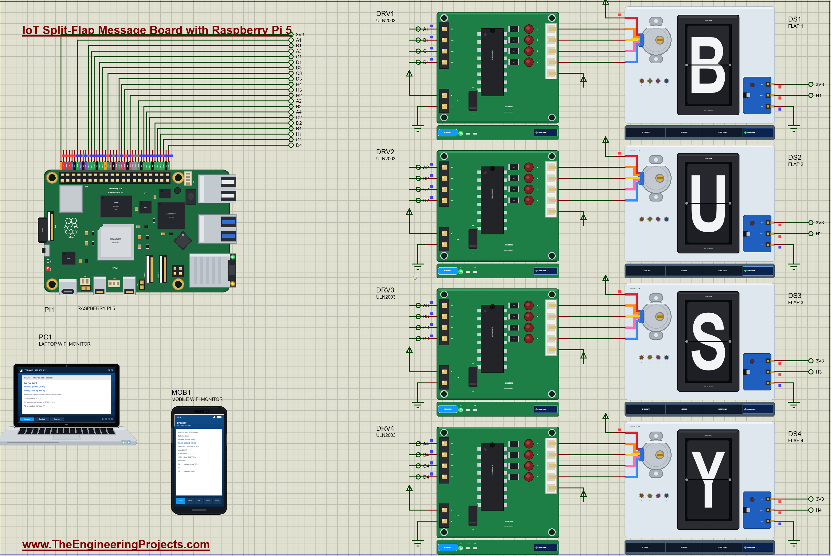
| Module | IN1 - IN4 (coils A - D) | HOME (hall sensor) |
|---|---|---|
| 1 (DRV1, DS1) | GPIO4, 17, 27, 22 (pins 7, 11, 13, 15) | GPIO26 (pin 37) |
| 2 (DRV2, DS2) | GPIO5, 6, 13, 19 (pins 29, 31, 33, 35) | GPIO7 (pin 26) |
| 3 (DRV3, DS3) | GPIO18, 23, 24, 25 (pins 12, 16, 18, 22) | GPIO8 (pin 24) |
| 4 (DRV4, DS4) | GPIO12, 16, 20, 21 (pins 32, 36, 38, 40) | GPIO11 (pin 23) |
| The hall boards' VCC | - | 3V3 (pin 1) |
Each ULN2003 board takes four inputs from the Pi and switches the motor's four coils to ground; its + and the motor's red common wire are on the 5 V supply. The hall sensor's board takes its 3.3 V from the Pi's own 3.3 V pin, so its HOME output, which has its own 10 kohm pull-up, is safe for the Pi's pins. (In our second test the boards ran from a separate 3.3 V supply in the simulation, and the Pi never saw HOME go high: wired to the Pi's own pin, every module found home.) That is 20 GPIO pins for four characters; a bigger board would use shift registers or one microcontroller per module.
How the Split-Flap Board Works
Inside a Split-Flap Module
The 40 flaps hang on a spool, printed with the top half of one character on the front and the bottom half of the next on the back. As the spool turns, a stop tab holds the top flap until the next one is pushed past it and falls, showing the next character. Each flap takes 9 degrees of the turn: flap k shows from k times 9 degrees, and the program aims for the middle of it, k times 9 plus 4.5 degrees. The spool can only go forwards: backwards, the flaps catch on the tab. So going from B back to A means going all the way round, through 39 flaps.
The 28BYJ-48 and the ULN2003
The motor is a 28BYJ-48, a small 5 V stepper with a 63.68 to 1 gearbox. Its four coils, A to D, share a red common wire on 5 V, and a coil is on while its end is pulled to ground: that is the ULN2003's job, a Darlington transistor array, one channel per coil. The program drives half steps: A, AB, B, BC, C, CD, D, DA, each one coil or two. That makes 4075.77 half steps a turn, not 4096 as many tutorials say: the gearbox is 63.68 to 1, not 64 to 1. Worked example: a program that counts 4096 is 20 half steps off after every turn, 1.8 degrees, and after five turns the flap shown is the next one.
Homing with a Hall Sensor
A stepper has no idea where it is when it powers up. So each module has a magnet on its spool and a hall sensor beside it: HOME goes low while the magnet passes, from 1.5 to 5.5 degrees into the blank flap. At the start, the program turns every module until HOME goes from high to low; at that moment the position is exactly 1.5 degrees, 17 half steps. A spool that powers up with the magnet already at the sensor reads low from the start, so the program waits for high and then the next low, one turn later. After that, every pass of the magnet sets the position again, so a lost step or a rounding error never adds up.
Speed, Ramps and Lost Steps
A stepper that is asked to jump from standstill to full speed cannot follow: its rotor falls behind the coils and it loses steps. The program ramps each move from 5 to 12 r/min over 120 half steps and back down at the end. At 12 r/min a half step comes every 1.23 ms, and a flap falls every 0.125 seconds, 102 half steps apart. Above about 17 r/min the module cannot keep up with the flaps' load; our first test, which jumped to full speed at once, lost up to 56 full steps on one module and showed the letter before the one asked for.
Planning a Word Change
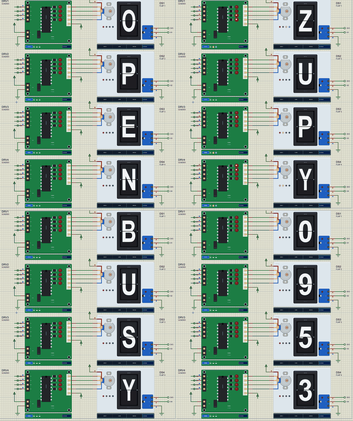
Because the spool only turns forwards, the distance to a letter is always counted ahead: from flap a to flap b it is b minus a flaps, plus 40 if that is negative. Worked example, OPEN to BUSY: module 1 goes from O (flap 15) to B (flap 2), 2 - 15 + 40 = 27 flaps; module 2 from P (16) to U (21), 5 flaps; module 3 from E (5) to S (19), 14 flaps; module 4 from N (14) to Y (25), 11 flaps. At 12 r/min a flap takes 0.125 seconds, so the longest move, 27 flaps, takes about 3.4 seconds plus the ramps, and the whole word is ready when module 1 is. A module whose letter does not change, like module 3's E from OPEN to FREE, does not move at all; turning it would mean a whole turn for nothing.
Four Motors from One Thread
Each module needs a half step every millisecond or so, and four of them must move at the same time. Four threads would fight over the CPU; instead, one thread keeps a clock for each moving module, the time its next half step is due, picks the earliest, sleeps until then, steps it and works out its next time from its own ramp. Only the coil that changes is written: every half step switches exactly one coil.
The Python Code Explained
The whole program is included in the download. It uses lgpio for the GPIO pins, threads for the stepping and the clock, and the standard library's http.server for the dashboard. At the top are the pins and the module's numbers:
MODULES = [((4, 17, 27, 22), 26), ((5, 6, 13, 19), 7), ((18, 23, 24, 25), 8), ((12, 16, 20, 21), 11)] # (IN1 - IN4, HOME), BCMSEQ = (0b0001, 0b0011, 0b0010, 0b0110, 0b0100, 0b1100, 0b1000, 0b1001) # half steps: A, AB, B, BC, C, CD, D, DA
HALF_PER_TURN = 4075.77 # 64 x 63.68: the 28BYJ-48's half steps a turn (NOT 4096)RPM_MIN, RPM_MAX, RAMP = 5.0, 12.0, 120 # a ramp from 5 to 12 r/min over 120 half steps (and back)A Module
return half_of(k * 9.0 + 4.5)go() works out how far forwards the spool must turn to reach the middle of the flap asked for:
            d = centre(k) - self.pos % HALF_PER_TURN
            while d < 1:
                d += HALF_PER_TURN
f = min(1.0, self.done / RAMP, self.left / RAMP)
return 60.0 / ((RPM_MIN + (RPM_MAX - RPM_MIN) * f) * HALF_PER_TURN)step() moves one half step and watches HOME; a falling edge means the magnet, and the position is set again:
if h == 0 and self.last == 1: # the magnet: the position is known again self.pos = half_of(HOME_DEG)The Stepping Thread
        m = min(moving, key=lambda x: x.next_t)
        if m.next_t > now:
            time.sleep(m.next_t - now)
if m.left <= 0 and not m.released and now - m.stop_t > RELEASE_S:
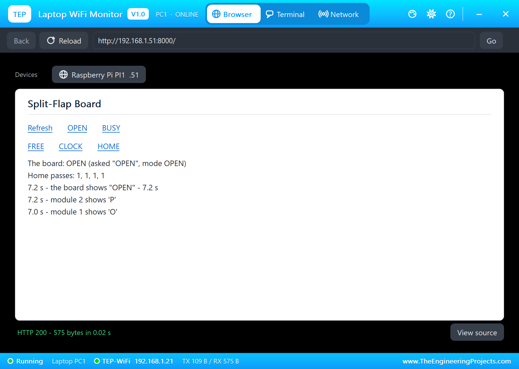
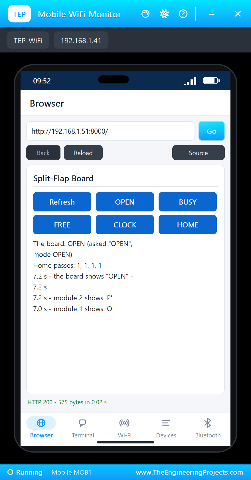
m.coils(0); m.released = TrueThe pages are / (the dashboard), /open, /busy and /free (the words), /clock (the time), /home (find home again) and /data (JSON). The dashboard puts its six links first and stays short, because the WiFi Monitors show one screen of a page.
How to Run the Proteus Simulation
- Download the project zip below and install the library files and the TEPPi folder (the steps are under the download button).
- Open Pi-5-Split-Flap-Message-Board.pdsprj from the Proteus Simulation folder. Keep splitflap_board.py and the DLL files next to it.
- Press Play. Every module turns to its magnet, then the board shows OPEN.
- Open the Laptop WiFi Monitor (PC1) or the Mobile WiFi Monitor (MOB1), press Go and try BUSY, FREE and CLOCK.
- Watch the modules' pop-ups: the flap in the window, the spool and the coils.
Simulation Results: the Split-Flap Board in Proteus
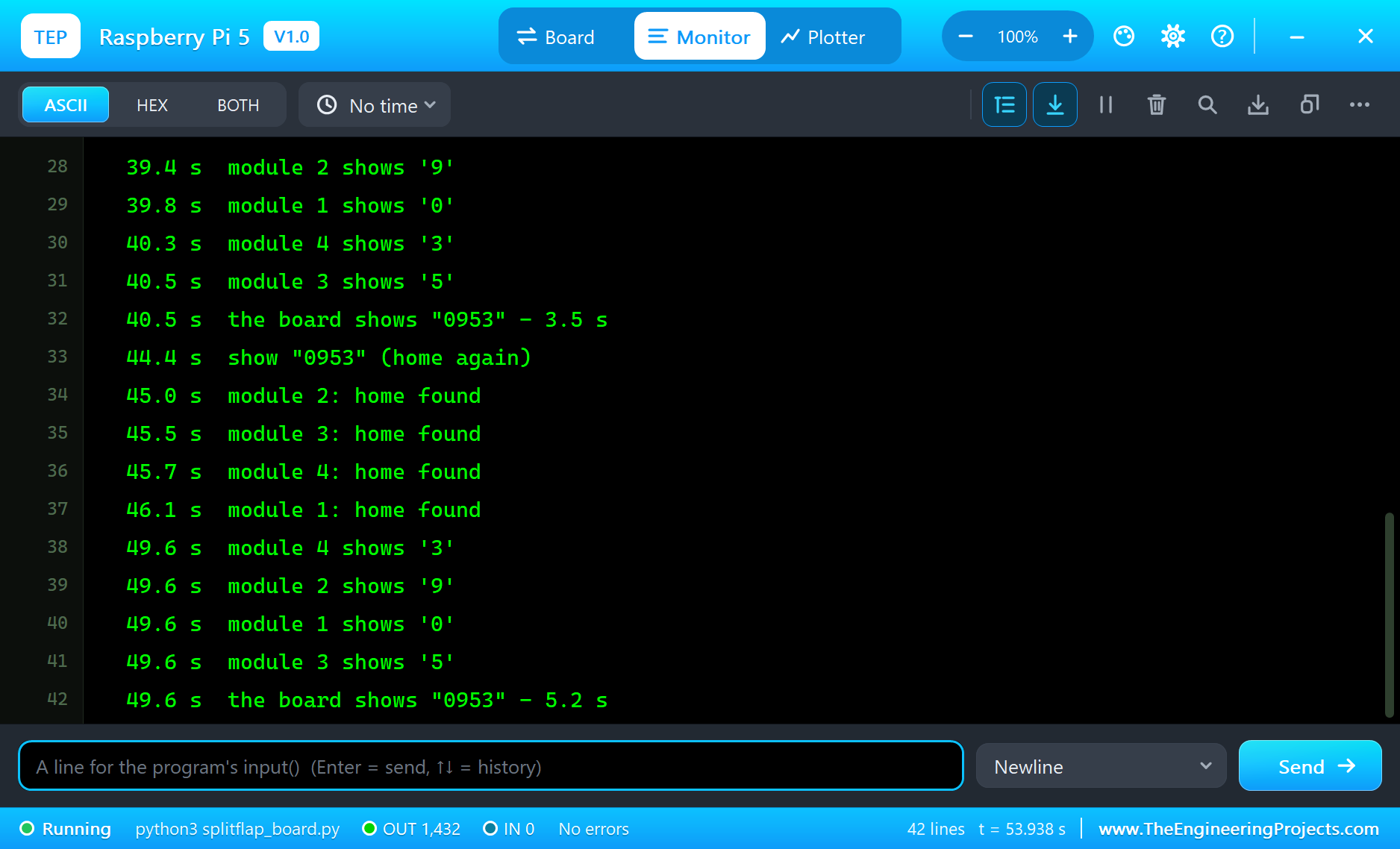
Here is the run that made the screenshots of this tutorial, 54.1 seconds of simulation. The times are the program's own, the seconds since it started, as it printed them in the Pi's terminal.
Homing and OPEN
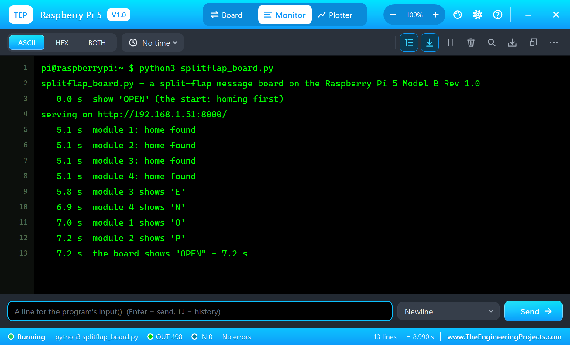
Every module powers up resting on its blank flap, and the blank flap is where the magnet is: HOME already reads low. So the program waits for high and then the next low, which means one whole turn. All four spools clatter round together through the 40 flaps, and at 5.1 seconds the terminal prints "module 1: home found" and the same for the other three: each is now exactly 17 half steps past the start of its blank flap.
Without stopping, each module carries on to its letter of OPEN: E at 5.8 seconds, N at 6.9, O at 7.0 and P at 7.2, and the program prints "the board shows "OPEN" - 7.2 s". Module 3 is first because E is only five flaps past the blank one; P is the furthest, sixteen flaps.
BUSY: the Flaps Falling
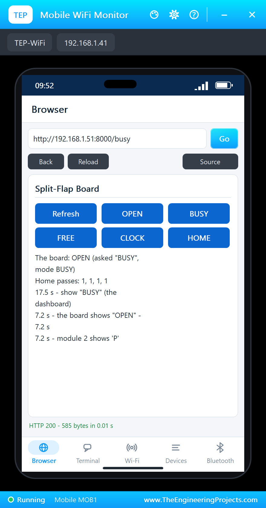
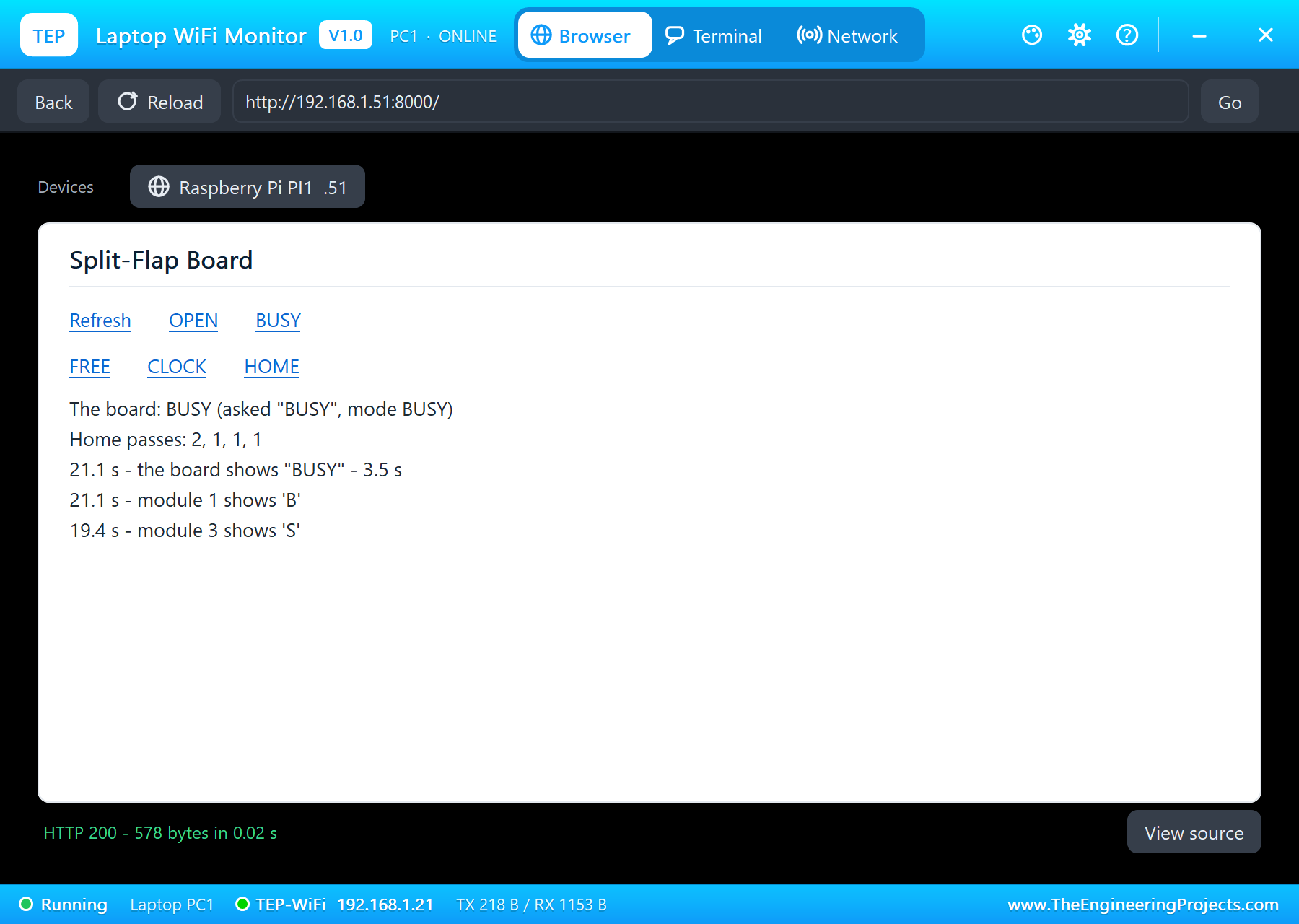
At 17.5 seconds BUSY on the phone sets all four spools turning. A sheet shot one second later catches the board in the middle of the change, showing Z, U, P and Y on its way. Module 2 only needs five flaps, P to U, and stops at 18.3 seconds; module 1 must go from O to B, which is backwards, so it goes all the way round, 27 flaps, and is last at 21.1 seconds. Its pop-up shows the ramp at the end of the move: 8.3 r/min and slowing as B comes up, and no lost steps.
FREE and the Clock
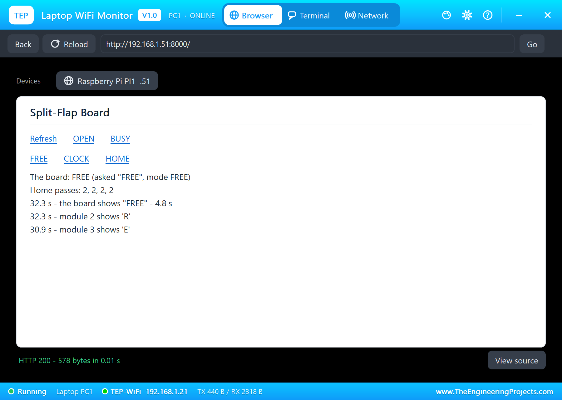
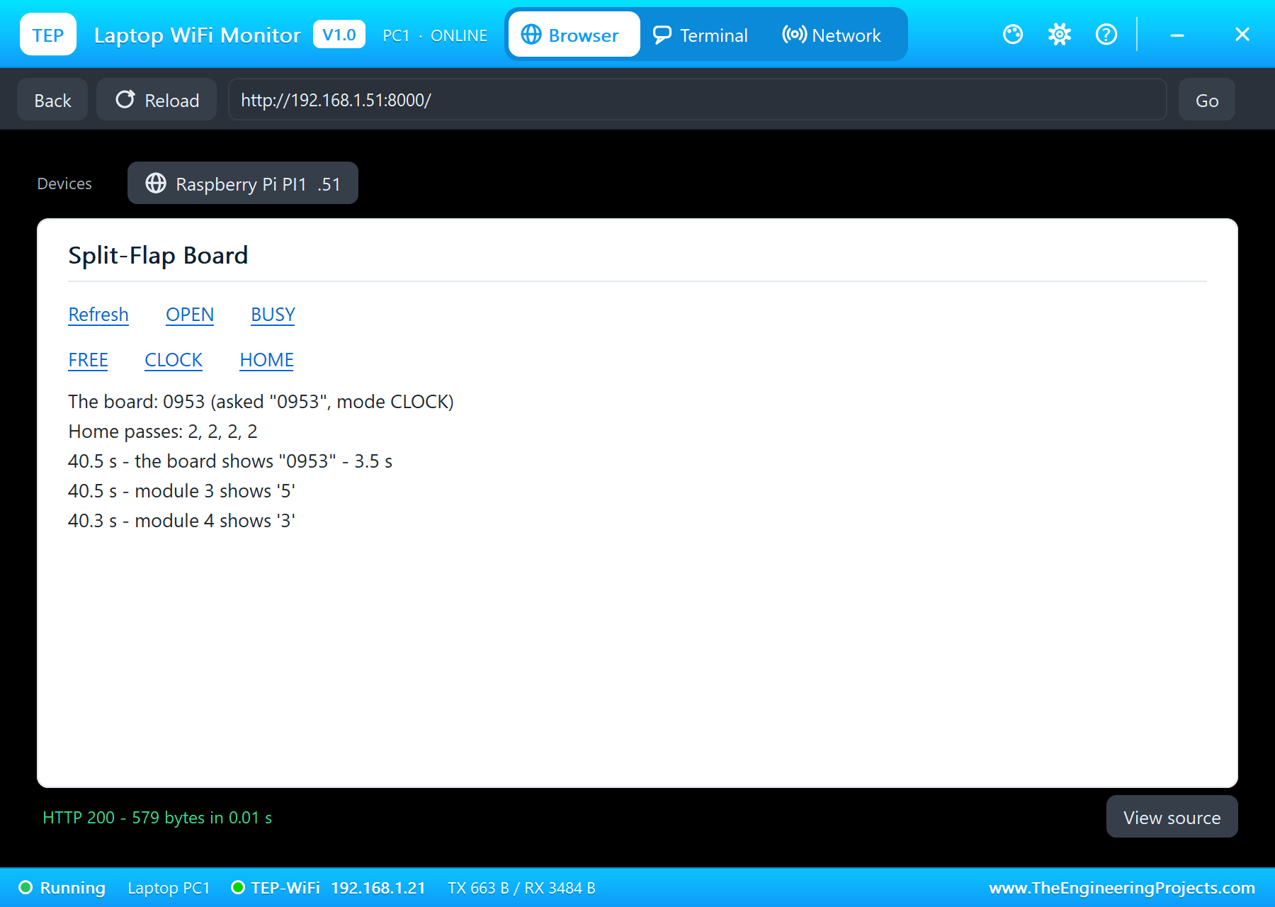
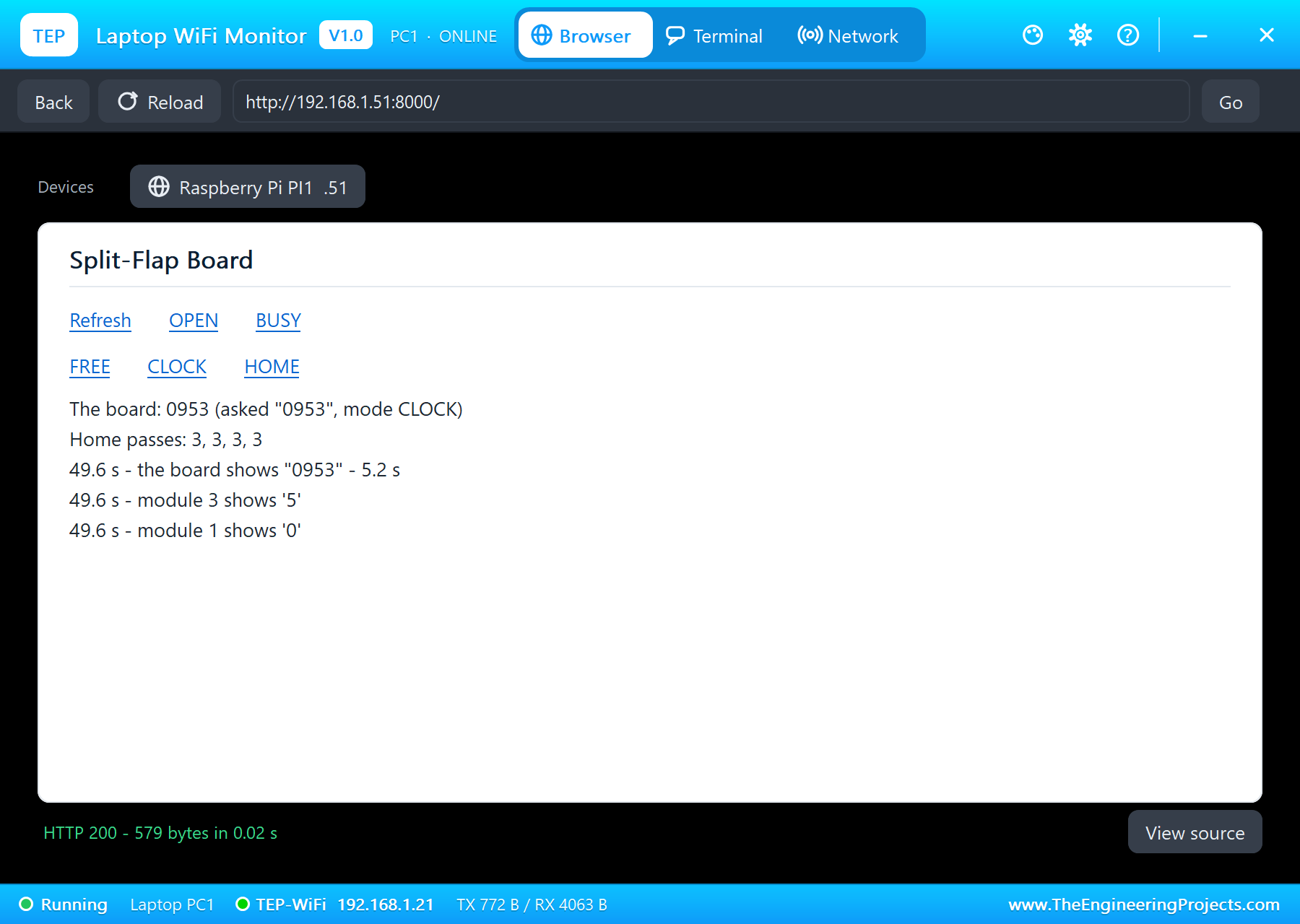
At 27.5 seconds FREE from the laptop: F at 28.2 seconds, the two Es at 30.2 and 30.9, and R last at 32.3, 4.8 seconds in all. Then CLOCK: the program reads the time and shows it as four digits, 0953, at 40.5 seconds. Every minute the clock thread shows the new time, and only the modules whose digit changes move.
Homing Again
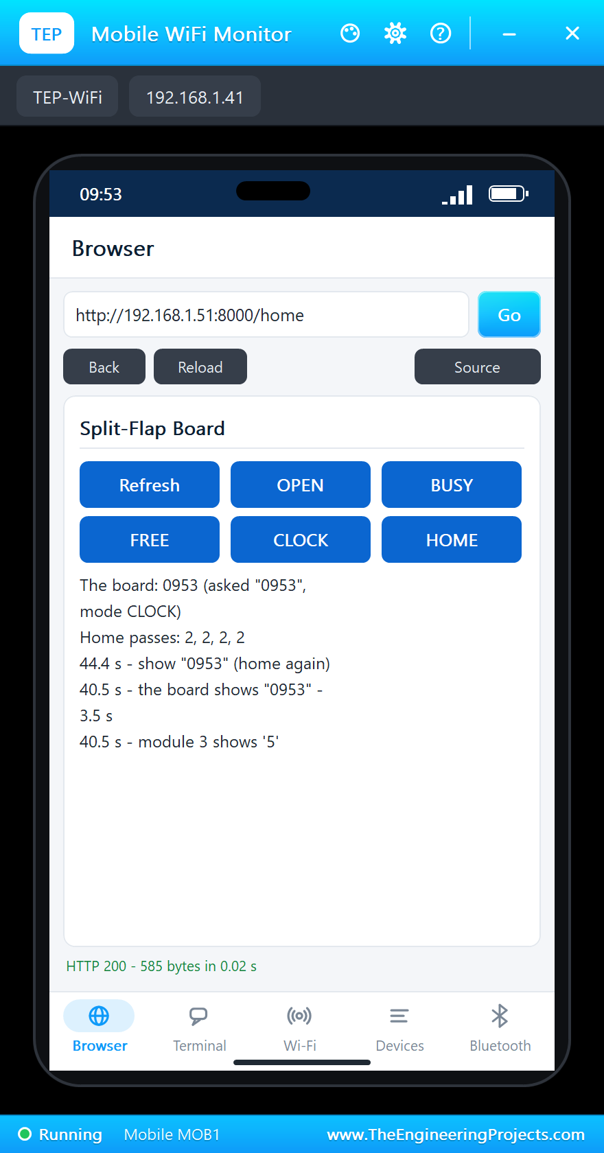
At 44.4 seconds HOME on the phone makes the program forget the positions. Each module turns forwards until its magnet passes, module 2 first at 45.0 seconds and module 1 last at 46.1, each from a different digit, and then on to its digit again: 0953 is back at 49.6 seconds. At the end of the run every module's pop-up agrees with the program: the flap it shows is the flap the program counts, after three home passes and 0 lost steps.
The Numbers of the Run
| Change | Asked at | Done at | The last module |
|---|---|---|---|
| Homing + OPEN | 0 s | 7.2 s (home at 5.1 s) | module 2, P |
| BUSY | 17.5 s | 21.1 s (3.5 s) | module 1, O to B: 27 flaps |
| FREE | 27.5 s | 32.3 s (4.8 s) | module 2, U to R |
| CLOCK 0953 | 37.0 s | 40.5 s (3.5 s) | module 3, 5 |
| HOME + 0953 | 44.4 s | 49.6 s (5.2 s) | all four at once |
Download the Project Files
Click the button below to download IoT-Split-Flap-Message-Board-Raspberry-Pi-5-Proteus-Simulation-v1.0.zip (about 13.3 MB, without the source code of the models):
IoT Split-Flap Message Board with Raspberry Pi 5 - Proteus Simulation V1.0- Proteus Simulation: Pi-5-Split-Flap-Message-Board.pdsprj, the program splitflap_board.py and copies of the models.
- Python Code: splitflap_board.py, the complete program.
- Proteus Library Files: the LIB files of the Raspberry Pi 5, the split-flap module, the ULN2003 board and the two WiFi Monitors.
- Proteus Model Files: the DLL models and the TEPPi folder, the Python 3.11 and the runtime that the Pi board runs.
- README.txt: the installation steps, the properties, the test results and the links to every library post.
No Proteus yet? Read How to Download and Install Proteus 7 and 8. New to libraries? Follow How to Install a New Library in Proteus.
How to Install the Project Files
- Close Proteus and extract the whole zip file, for example to your Desktop.
- Copy the files from Proteus Library Files into the LIBRARY folder of Proteus.
- Copy everything in Proteus Model Files, the DLL files and the TEPPi folder, into the MODELS folder.
- Start Proteus and open the project from the Proteus Simulation folder.
Changing the Code
The program is plain Python 3: edit splitflap_board.py beside the project and press Play again; the Pi board runs the new file. The words, the speed and the pins are at the top. The same program runs on a real Raspberry Pi 5 with Raspberry Pi OS and lgpio. For our other Raspberry Pi 5 project with smooth motion control, see the IoT Robot Arm Controller with Raspberry Pi 5.
Ideas to Extend the Project
- Add more modules with shift registers, or give each module its own small microcontroller on an I2C bus.
- Show the next train or bus from an online timetable.
- Let the dashboard take any four-letter word.
- Scroll a longer message across the four modules.
- Add a microphone and a speaker for the famous clatter, or count the flaps for a sound effect.
- Run the clock in 12-hour format with a dot flap for the half hours.
From Simulation to Real Hardware
- Power the motors from their own 5 V supply: a 28BYJ-48 coil is 50 ohm, 100 mA at 5 V, so two coils on take 200 mA and four modules about 0.8 A; never from the Pi's 5 V pin.
- Keep the hall sensor at 3.3 V: the Pi's pins are not 5 V tolerant.
- Switch the coils off at rest: they get warm, and the gearbox holds the spool anyway.
- Mind Linux timing: a busy Pi can pause the stepping thread; give the program a higher priority, or let a microcontroller do the stepping.
- Count the real steps a turn: measure your motor's steps between two home passes; 4075.77 is typical, but gearboxes differ.
Troubleshooting
- A module never finds home: HOME is not on the right GPIO, or the hall board has no VCC.
- A module shows the letter next to the one asked: the steps a turn are wrong, or it lost steps on a fast start.
- A module hums and stops: too fast, a missing ramp, or driven backwards.
- The coils get warm: they stay on; switch them off after a stop.
- The terminal cannot start Python: the TEPPi folder is not in MODELS.
Limitations of the Simulation
- The flaps' clatter is silent: the pop-ups show it.
- The clock shows the time of the computer running the simulation.
- The network is simulated: the dashboard travels between the Pi and the two monitors inside Proteus; the times in this tutorial are simulation time.
- Raspberry Pi is a trademark of Raspberry Pi Ltd; the 28BYJ-48 and the ULN2003 are made by several companies. This project is not made or endorsed by them or by Labcenter.
So, that was all about the IoT Split-Flap Message Board with Raspberry Pi 5 - Proteus Simulation. I hope it helps you build your own clattering sign: four steppers driven in half steps through ULN2003 boards, a hall sensor that tells each spool where home is, ramps that keep every step, and one thread that runs four motors at once, all tested in a simulation before you cut a single flap. More IoT projects with the ESP32 and the Raspberry Pi 5 are coming in this series. If you have any questions, ask in the comments and I will help you out. Till the next tutorial, take care and have fun!