Hello friends, I hope you all are doing great. Today, I am going to share the IoT Digital Compass with Raspberry Pi 5 - Proteus Simulation, the thirtieth project of our IoT Projects series. If you have searched for a Proteus simulation of a Raspberry Pi compass with a GY-271 magnetometer and a TFT display, here is a complete one. A Raspberry Pi 5 reads the Earth's magnetic field from a QMC5883L on a GY-271 module, works out the heading, draws a turning compass card on a 2.4-inch ILI9341 TFT, calibrates out a magnet fixed near the sensor, adds the magnetic declination, warns when something disturbs the field, and serves a live web dashboard that you can open on a laptop or a phone.
A digital compass is in every phone, drone and car navigation system, and it is more interesting than it looks: the sensor measures a tiny field, about a hundred times weaker than a fridge magnet, and anything magnetic near it pulls the reading off. In this tutorial, we will go through the circuit, learn what a magnetometer measures and how the heading comes from two of its axes, read the QMC5883L over I2C, see why a nearby magnet ruins the heading and how a calibration turn removes it, add the declination, drive the ILI9341 over SPI and draw on it from frame buffers, walk through the Python program, and then run the simulation: the board turned to north, east and southwest, a magnet on the board, a calibration while the board spins, the declination, and a tilt that shows why phones also need an accelerometer. At the end, you can download the project with the program, every library file and the Python runtime the Pi needs.
NOTICE: Our team has put a lot of effort into this project: the circuit, the code and every part in the simulation are our own work, and you get them all free. Your feedback is the fuel that keeps us going, so please tell us what you think in the comments below. And if our free projects help you, you can buy us a coffee. So, let's get started with the IoT Digital Compass with Raspberry Pi 5 - Proteus Simulation:
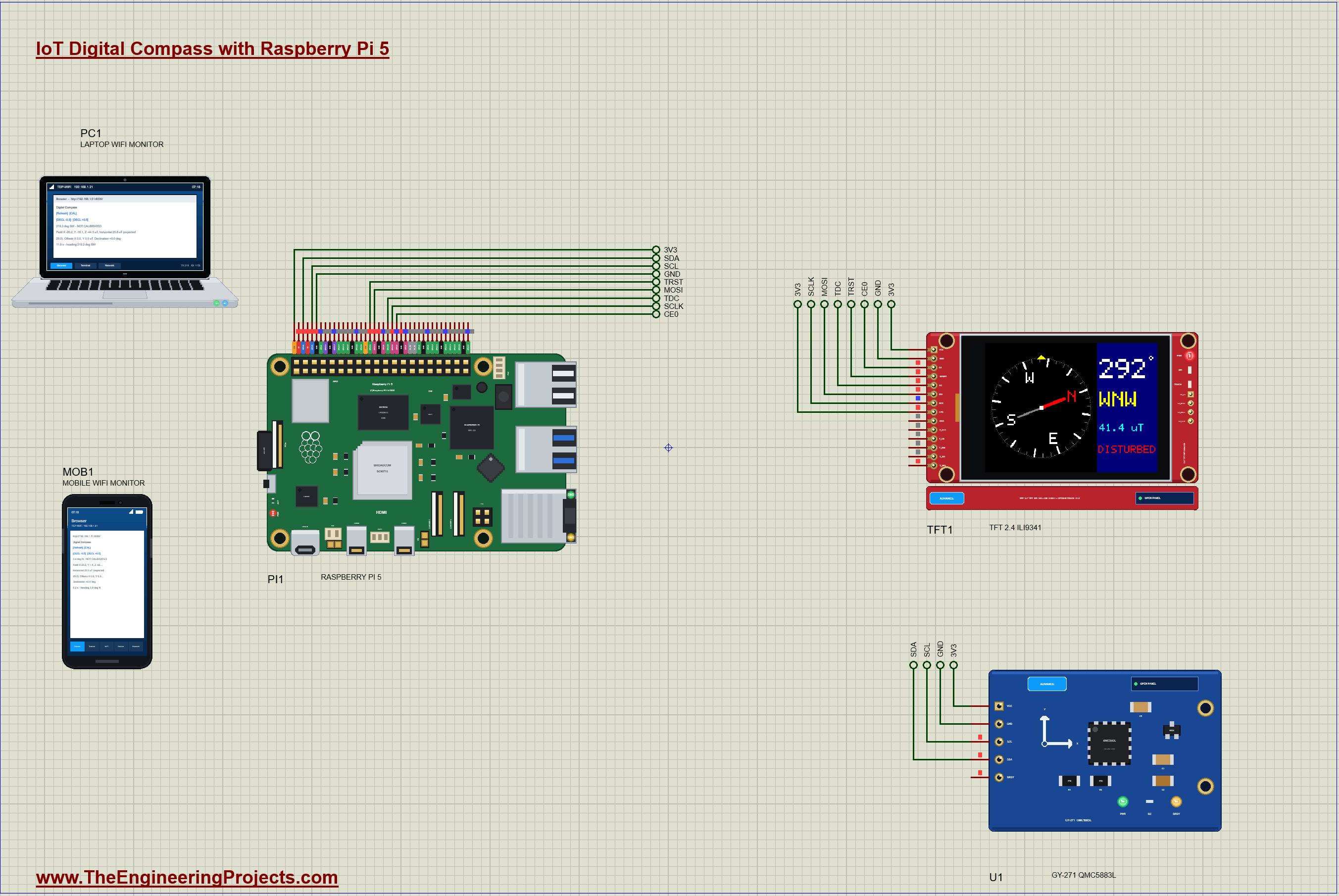
What Does This Digital Compass Do?
- Measures the Earth's field: X, Y and Z from a QMC5883L, 30 counts a microtesla, 200 readings a second.
- Works out the heading: 0 to 360 degrees clockwise from magnetic north, and the 16 compass points.
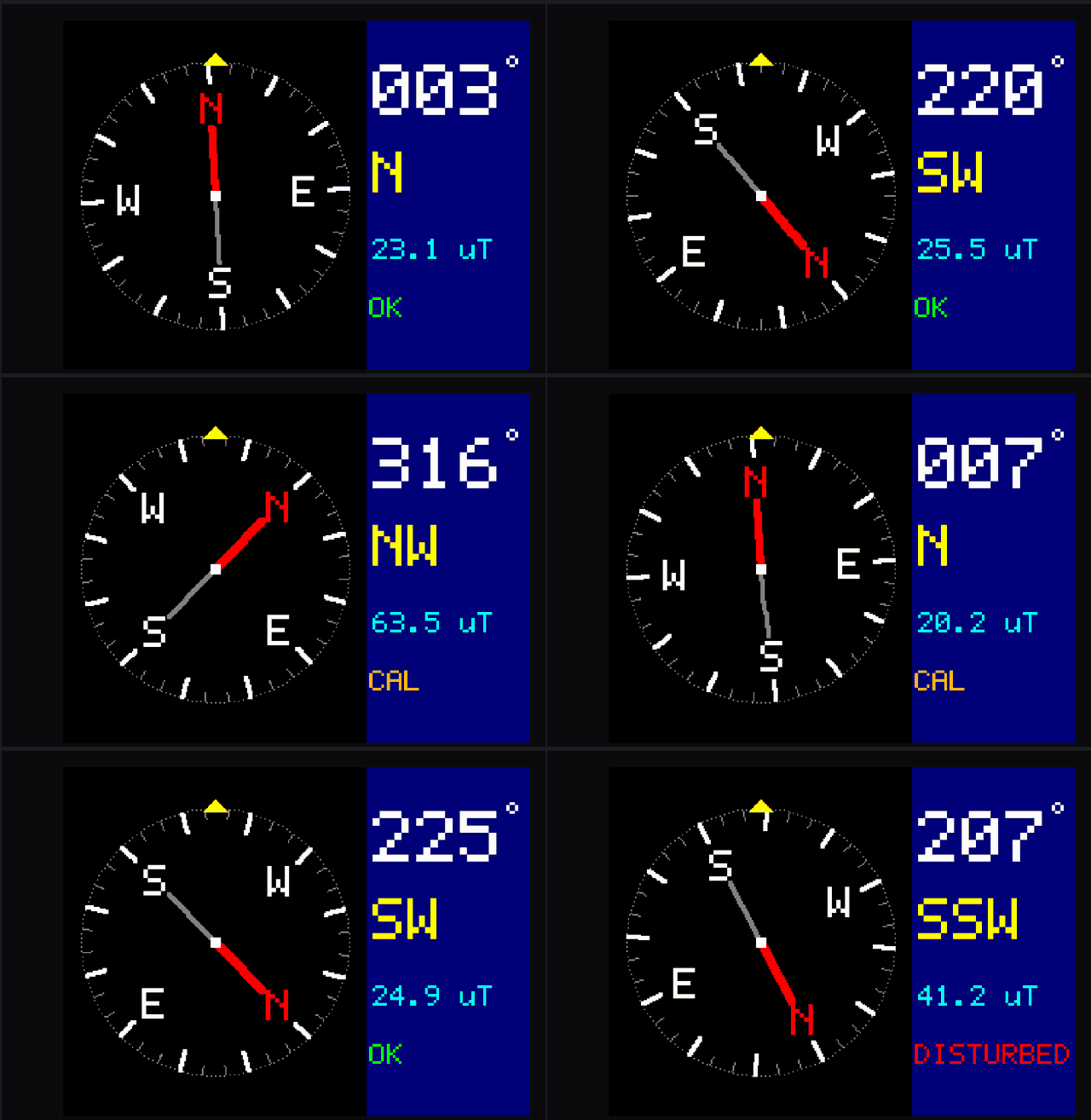
- A turning compass card: drawn on a 2.4-inch TFT, N always pointing north, a yellow mark where the board points.
- Calibrates out magnets: one full turn of the board finds the hard-iron offsets.
- Adds the declination: the angle between magnetic and true north, in half-degree steps.
- Warns of disturbance: a horizontal field far from its calibrated strength means a magnet nearby or a tilted board.
- A dashboard: the heading, the field, the offsets, CAL and the declination from a laptop or a phone.
It is a great project for learning I2C, SPI, a little trigonometry and the art of calibration. In the simulation, the GY-271's pop-up turns the board, puts a magnet on it and tilts it, and the TFT's pop-up shows the screen.
Components Used in the Proteus Simulation
All the parts come from our Proteus libraries, each with its own tutorial. The project zip at the end includes every LIB and DLL file.
| Part | Proteus device | Library post | Connection |
|---|---|---|---|
| Raspberry Pi 5 | RASPBERRY PI 5 | Raspberry Pi 5 Library for Proteus | PI1, Ethernet 192.168.1.51 |
| GY-271 with the QMC5883L | QMC5883LADVTEP | HMC5883L / QMC5883L Compass Library for Proteus | U1, I2C1 at 0x0D |
| TFT 2.4" ILI9341, 320 x 240 | TFT24ILI9341ADVTEP | TFT ILI9341 Library for Proteus | TFT1, SPI0 CE0 |
| Laptop WiFi Monitor | LAPTOP WIFI MONITOR | Laptop WiFi Monitor | PC1 |
| Mobile WiFi Monitor | MOBILE WIFI MONITOR | Mobile WiFi Monitor | MOB1 |
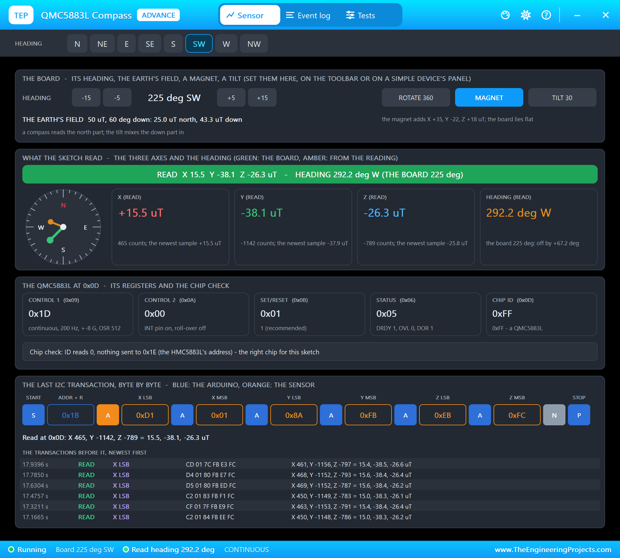
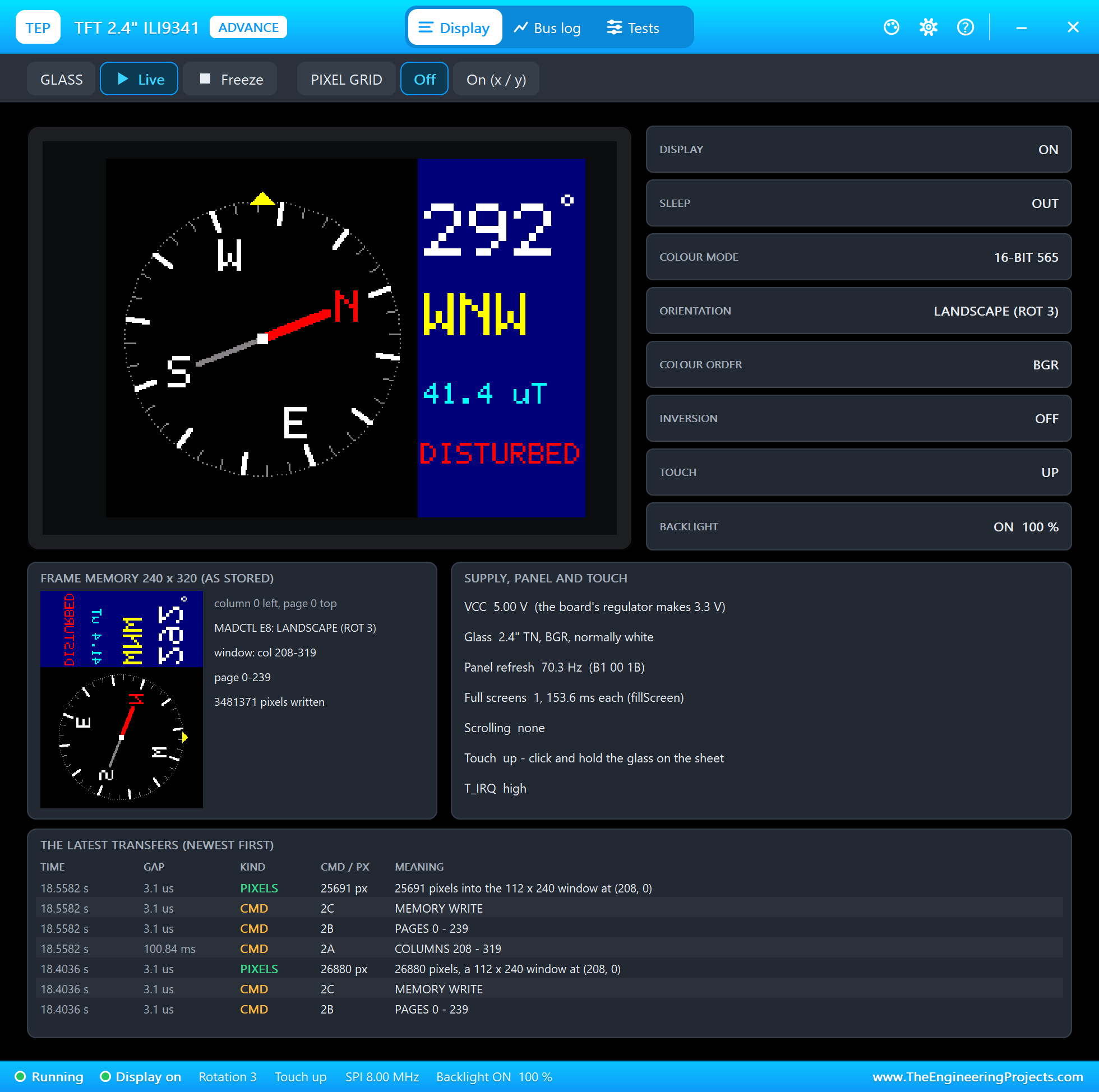
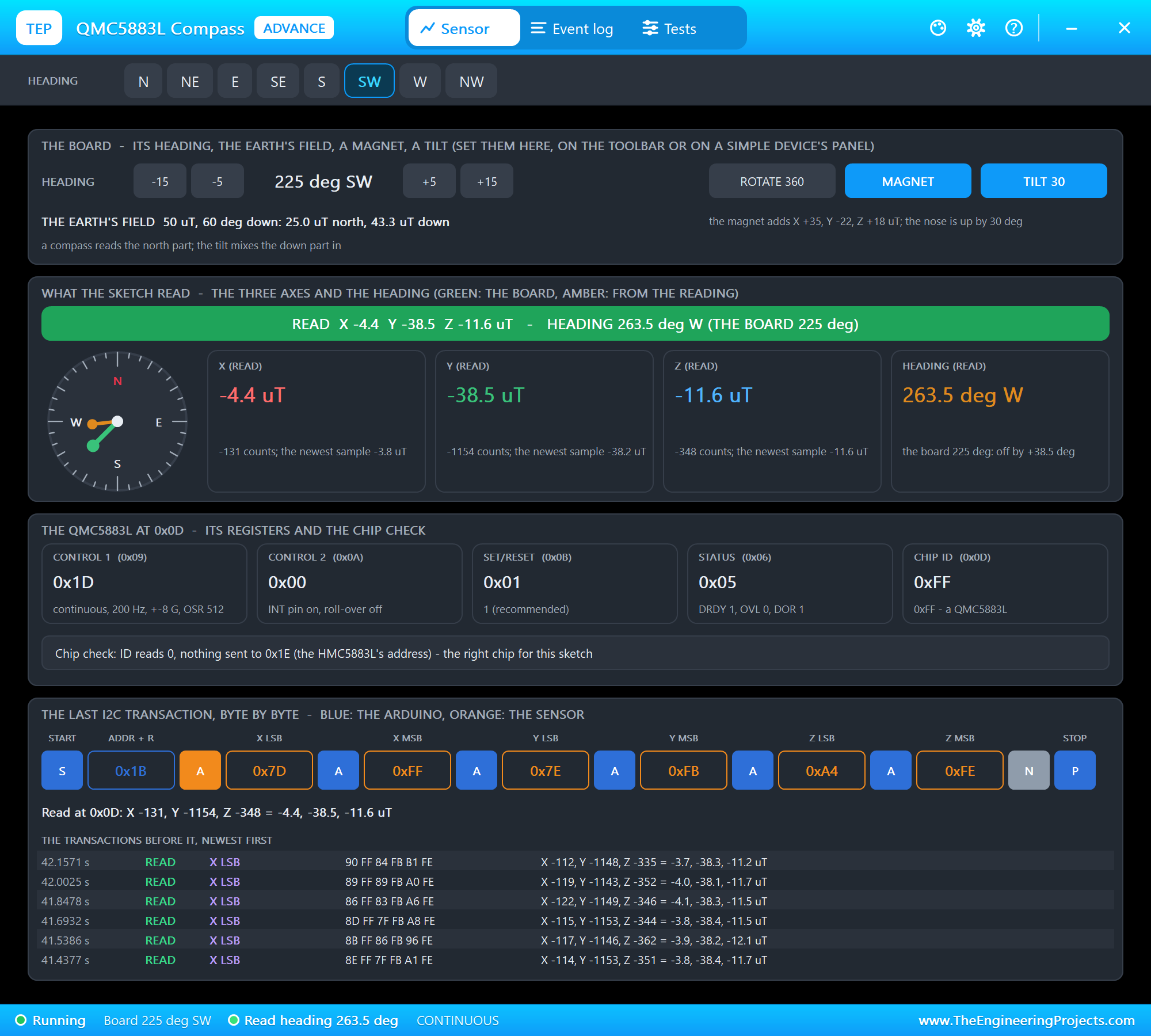
Both parts are models with pop-ups. The GY-271's pop-up sets the board's heading, puts a magnet on it, tilts it or turns it a full circle, and shows what the program read, the heading from that reading, the chip's registers and the last I2C transaction byte by byte. The TFT's pop-up shows the screen, the commands the controller received and the SPI traffic.
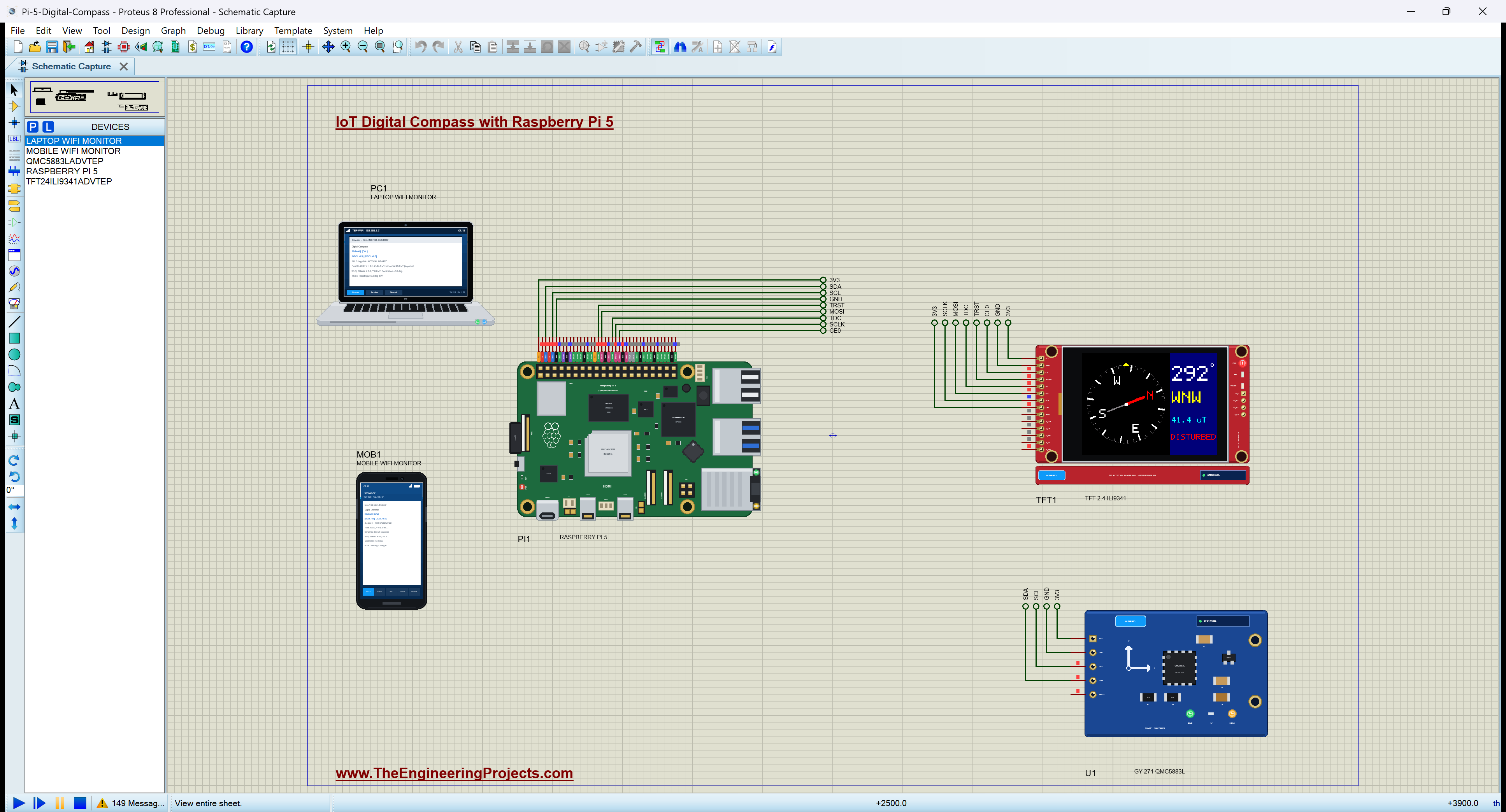
Proteus Simulation of the Digital Compass: the Circuit
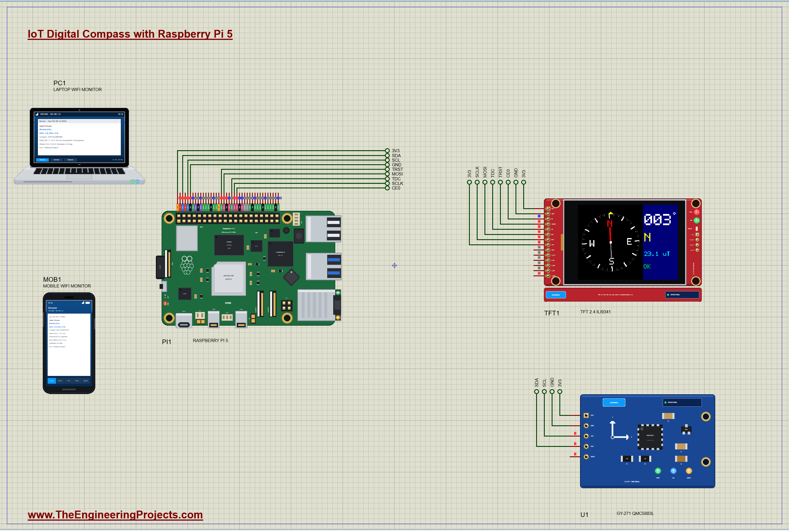
| Part | Pins | Raspberry Pi 5 header |
|---|---|---|
| U1 GY-271 | VCC / GND / SDA / SCL | 3V3 (pin 1) / GND (pin 6) / SDA1 GPIO2 (pin 3) / SCL1 GPIO3 (pin 5) |
| TFT1 ILI9341 | CS / DC / RESET | CE0 GPIO8 (pin 24) / GPIO25 (pin 22) / GPIO24 (pin 18) |
| TFT1 ILI9341 | SDI / SCK | MOSI GPIO10 (pin 19) / SCLK GPIO11 (pin 23) |
| TFT1 ILI9341 | VCC / LED / GND | 3V3 (pin 1) / 3V3 (pin 1) / GND (pin 6) |
The GY-271 shares the Pi's I2C bus and takes its 3.3 V from the header. The TFT sits on SPI0 with two extra pins: DC tells the controller whether a byte is a command or data, and RESET restarts it. Its VCC and its backlight LED take the Pi's 3.3 V too, and its logic pins work at the Pi's 3.3 V levels. The touch controller's pins stay unused. (Many 2.4-inch modules also have a regulator and accept 5 V on VCC; at 3.3 V, some of them want the regulator bypassed with the J1 jumper - check yours.)
How the Digital Compass Works
What a Magnetometer Measures
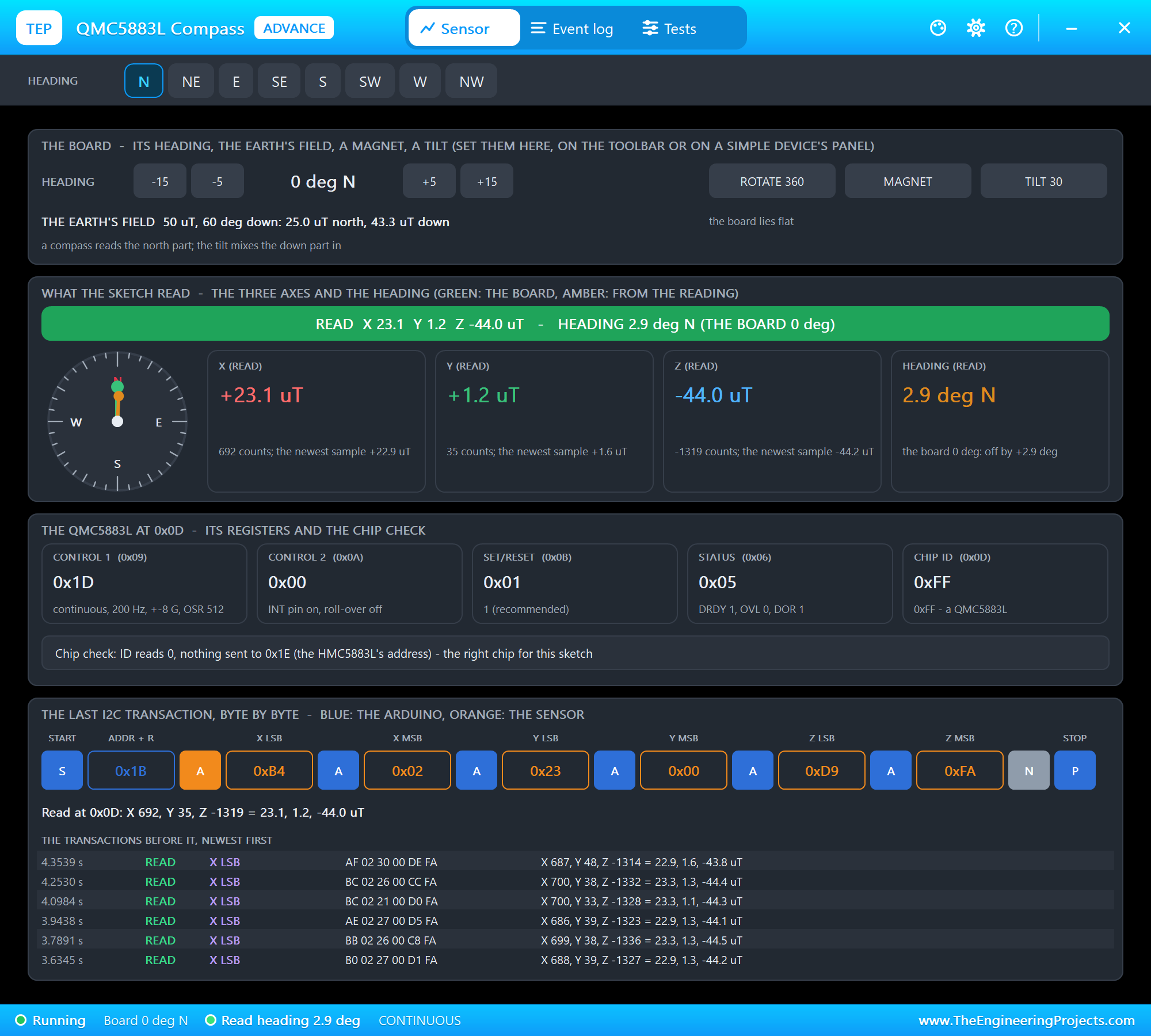
The Earth's magnetic field points north and, in most places, also down into the ground: in the simulation it is 50 microtesla, 60 degrees below the horizon, so 25 microtesla point north and 43.3 point down. The QMC5883L measures the field along its three axes with magnetoresistive sensors, 16 bits each. At its plus or minus 8 gauss range, 3,000 counts are one gauss, so 30 counts are one microtesla. Lying flat, the chip's X and Y axes see only the horizontal, northward part of the field, split between them by the board's heading.
The Heading from Two Axes
With the board flat, X = 25 cos(heading) and Y = 25 sin(heading), so the heading is atan2(Y, X), turned into degrees from 0 to 360. Worked example from our run: at the start the program read X = 23.1 and Y = 1.5 microtesla, and atan2(1.5, 23.1) = 3.7 degrees, although the board pointed exactly north. Every real chip has small offsets of its own, here a few tenths of a microtesla on each axis, and they are enough to move the heading by almost 4 degrees. The program averages four readings as vectors, not as angles, so 359 and 1 degree average to 0, not to 180.
Hard Iron and the Calibration Turn
A magnet, a steel screw or a speaker near the sensor adds its own constant field, and it turns with the board. Turn the board a full circle and the X and Y readings, which should draw a circle around zero, draw the same circle shifted: its centre is the unwanted field, the hard-iron offset. The calibration therefore asks for one full turn and keeps the lowest and the highest X and Y: the middle of each range is the offset, and half the range is the true horizontal field. Worked example: if X runs from 10 to 60 microtesla during the turn, its offset is 35 and the field 25. After that, the heading is atan2 of the readings minus the offsets.
Declination and Disturbance
A compass points to magnetic north, not to the geographic North Pole. The angle between them, the declination, depends on where you are, and it is a few degrees in most countries; east is positive. The program simply adds it. It also watches the strength of the corrected horizontal field: if it moves more than 25 percent away from the calibrated value, something magnetic is near the sensor, or the board is tilted, and the heading is not to be trusted. The screen and the dashboard then say DISTURBED.
Drawing on the ILI9341
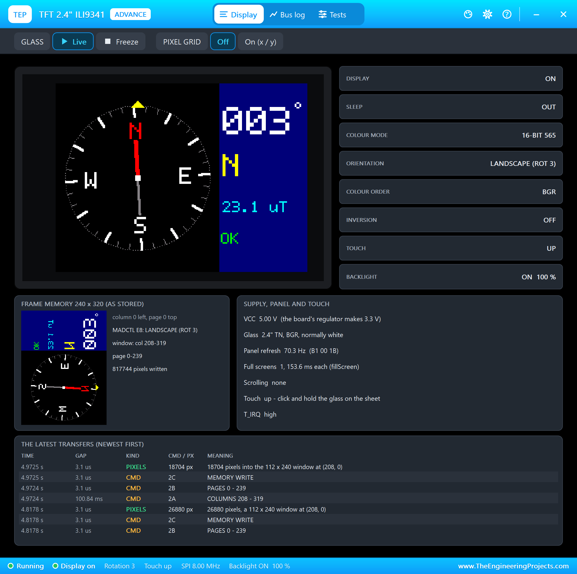
The ILI9341 controls a 240 x 320 glass. The Pi sends it commands with DC low and their data with DC high: SLPOUT wakes it, COLMOD 0x55 picks 16 bits a pixel, MADCTL 0xE8 turns the picture to landscape, 320 x 240, the right way up with the module's header on the left, and DISPON switches the glass on. To draw, the program sets a window with CASET and PASET and sends RAMWR followed by the window's pixels, two bytes each in the RGB565 format: 5 bits of red, 6 of green, 5 of blue. Worked example: red is 0xF800, yellow 0xFFE0. The controller takes writes up to 10 MHz, so the program asks for exactly that; in the simulation the Pi's SPI ran at 8 MHz, as the TFT's pop-up measured, safely below the limit.
Sending pixels one by one would mean thousands of tiny SPI transfers. Instead, the program draws each part of the screen into a frame buffer in the Pi's memory and sends it in one write: the compass card is 200 x 200 pixels, 80,000 bytes, 80 ms at 8 MHz, sent only when the heading changes by half a degree. The text uses our own 5 x 7 pixel font, scaled up.
The Python Code Explained
The whole program is included in the download. It uses lgpio for the I2C bus and the TFT's DC and RESET pins, spidev for the SPI bus, the math module for the angles, threads for the compass and the calibration, and the standard library's http.server for the dashboard. At the top are the numbers:
COUNTS_PER_UT = 30.0                                     # +-8 G: 3000 counts a gauss
CAL_S = 10.0                                             # s of turning for a calibration
H_NOMINAL = 25.0                                         # uT: the horizontal field before a calibration (50 uT, 60 degrees down)
DISTURBED = 0.25                                         # the horizontal field off by more than 25 %: something magnetic nearby
The QMC5883L
lgpio.i2c_write_byte_data(self.h, 0x09, 0x1D) # OSR 512, +-8 G, 200 Hz, continuous n, b = lgpio.i2c_read_i2c_block_data(self.h, 0x00, 6) v = [int.from_bytes(bytes(b[k:k + 2]), 'little', signed=True) for k in (0, 2, 4)]The Heading and the Calibration
heading = (math.degrees(math.atan2(ay, ax)) + decl) % 360 s['off_x'], s['off_y'] = (hi[0] + lo[0]) / 2, (hi[1] + lo[1]) / 2 disturbed = abs(h_ut - h_ref) > DISTURBED * h_refThe TFT
self.cmd(0x36, [0xE8]) # landscape, header on the left (row / column exchange + both mirrors), BGR self.cmd(0x2A, [x >> 8, x & 0xFF, (x + w - 1) >> 8, (x + w - 1) & 0xFF]) self.spi.writebytes2(data)The compass card turns by minus the heading, so its N stays on magnetic north while the yellow mark at the top shows where the board points:
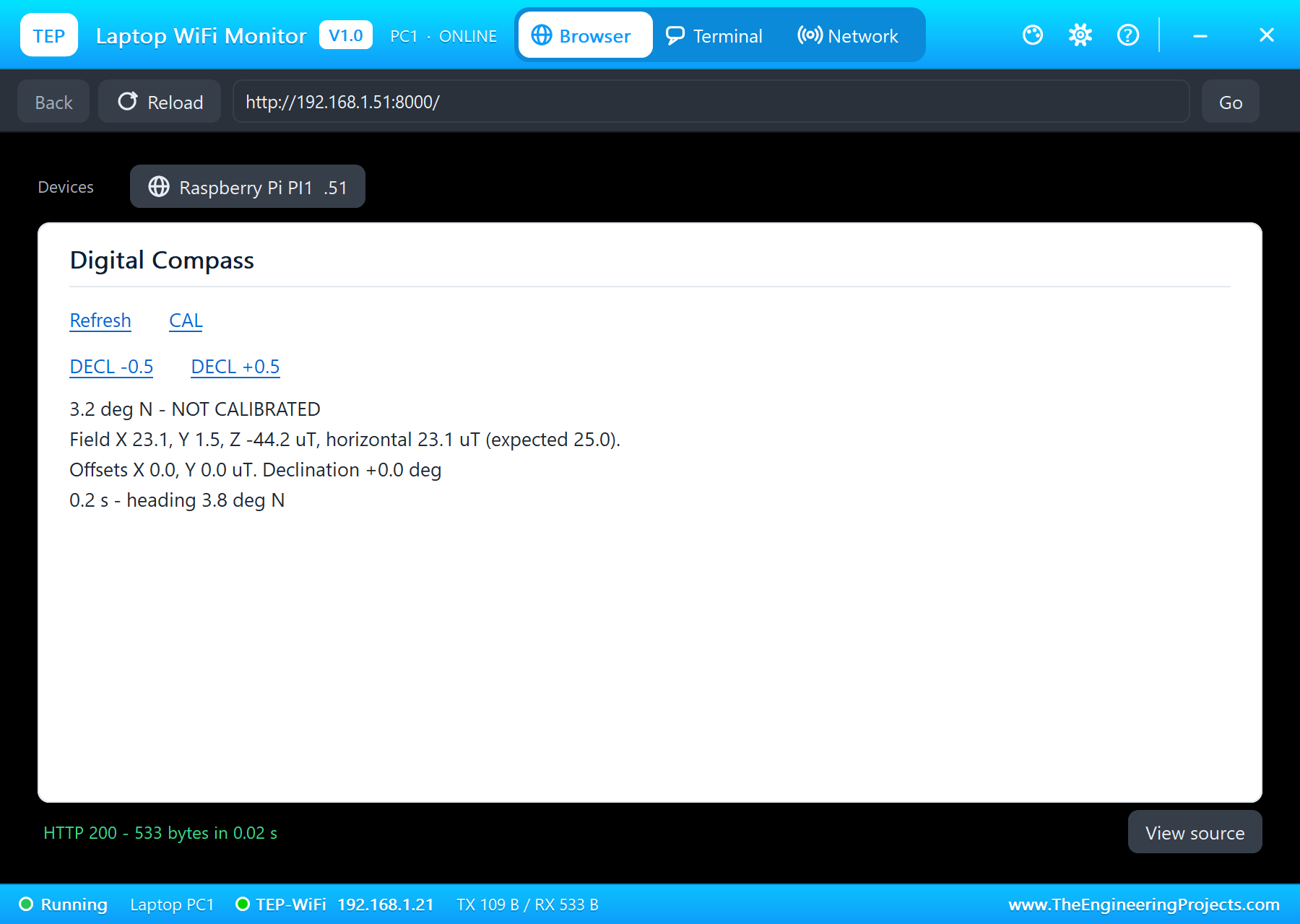
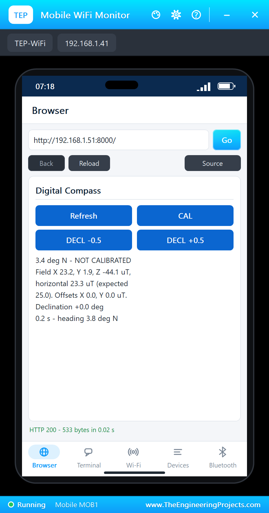
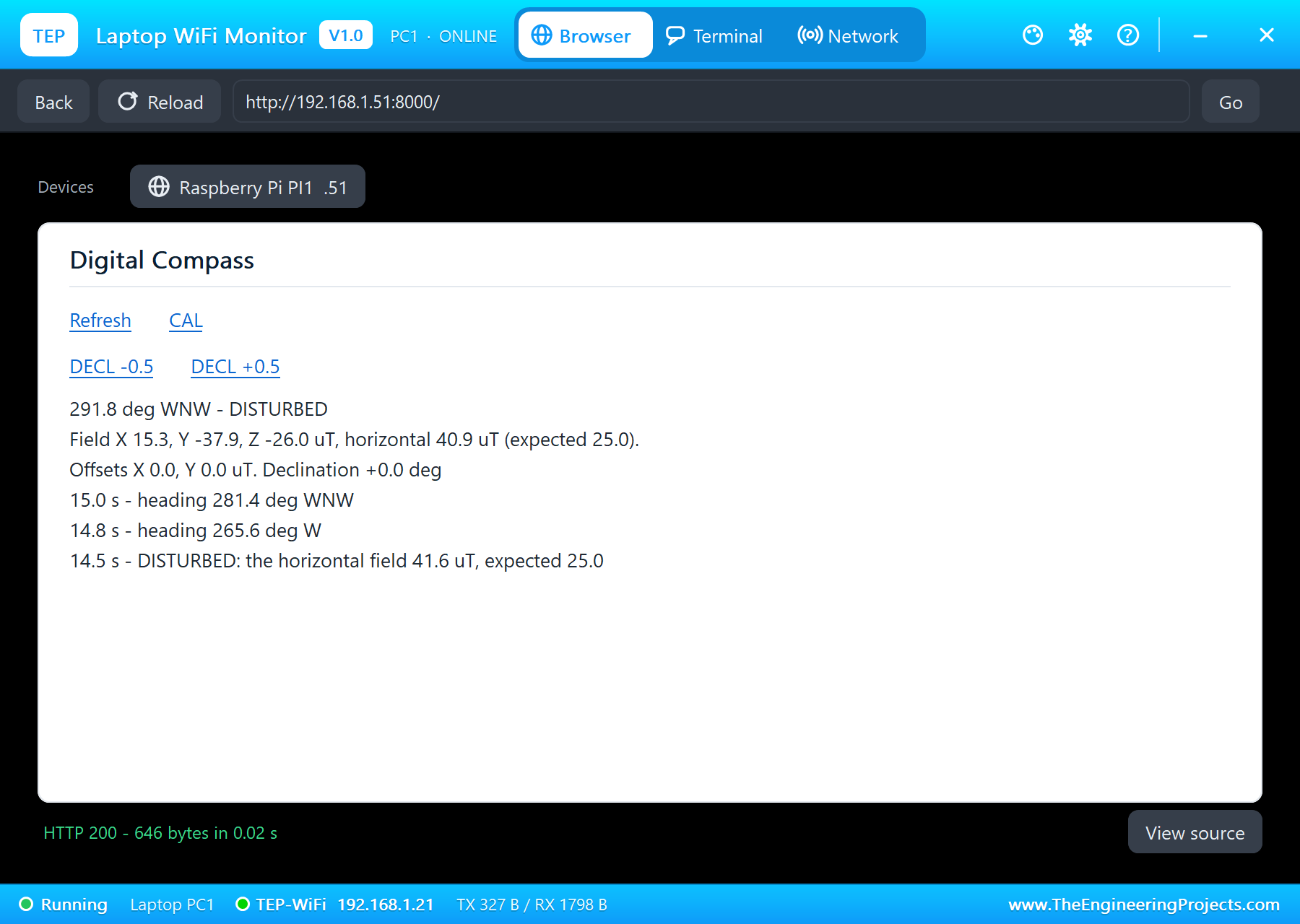
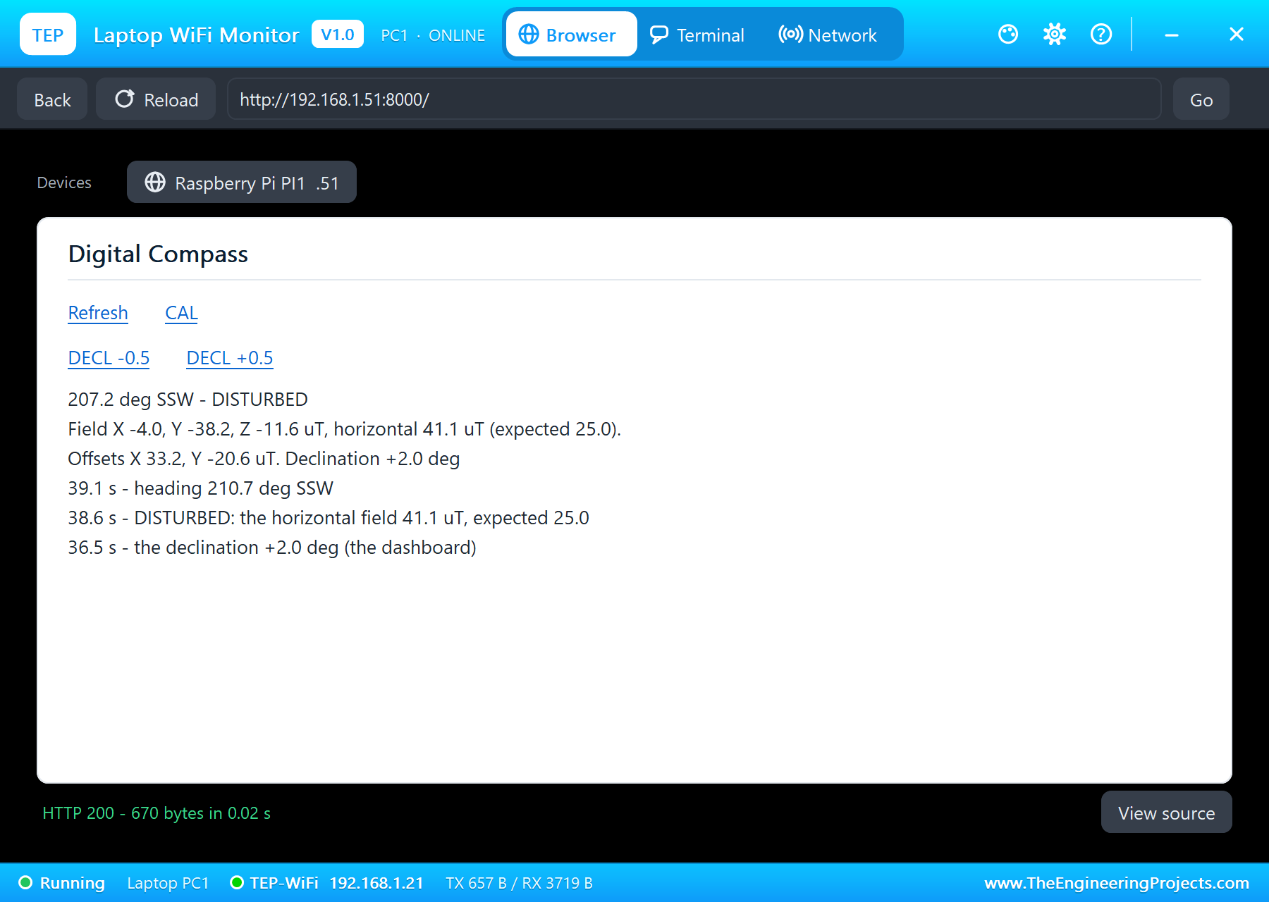
a = math.radians(deg - heading)The pages are / (the dashboard), /cal (a 10-second calibration), /decl_down and /decl_up (the declination -/+ 0.5 degree) and /data (JSON). The dashboard puts its links first and stays short, because the WiFi Monitors show one screen of a page.
How to Run the Proteus Simulation
- Download the project zip below and install the library files and the TEPPi folder (the steps are under the download button).
- Open Pi-5-Digital-Compass.pdsprj from the Proteus Simulation folder. Keep digital_compass.py and the DLL files next to it.
- Press Play. The TFT shows the compass card with the board pointing north.
- In the GY-271's pop-up (U1), turn the board with the compass points or the -15 / +15 buttons.
- Open the Laptop WiFi Monitor (PC1) or the Mobile WiFi Monitor (MOB1) and press Go.
- Put the MAGNET on the board, press CAL on the dashboard and, within 10 seconds, ROTATE 360 in the pop-up.
Simulation Results: the Digital Compass in Proteus
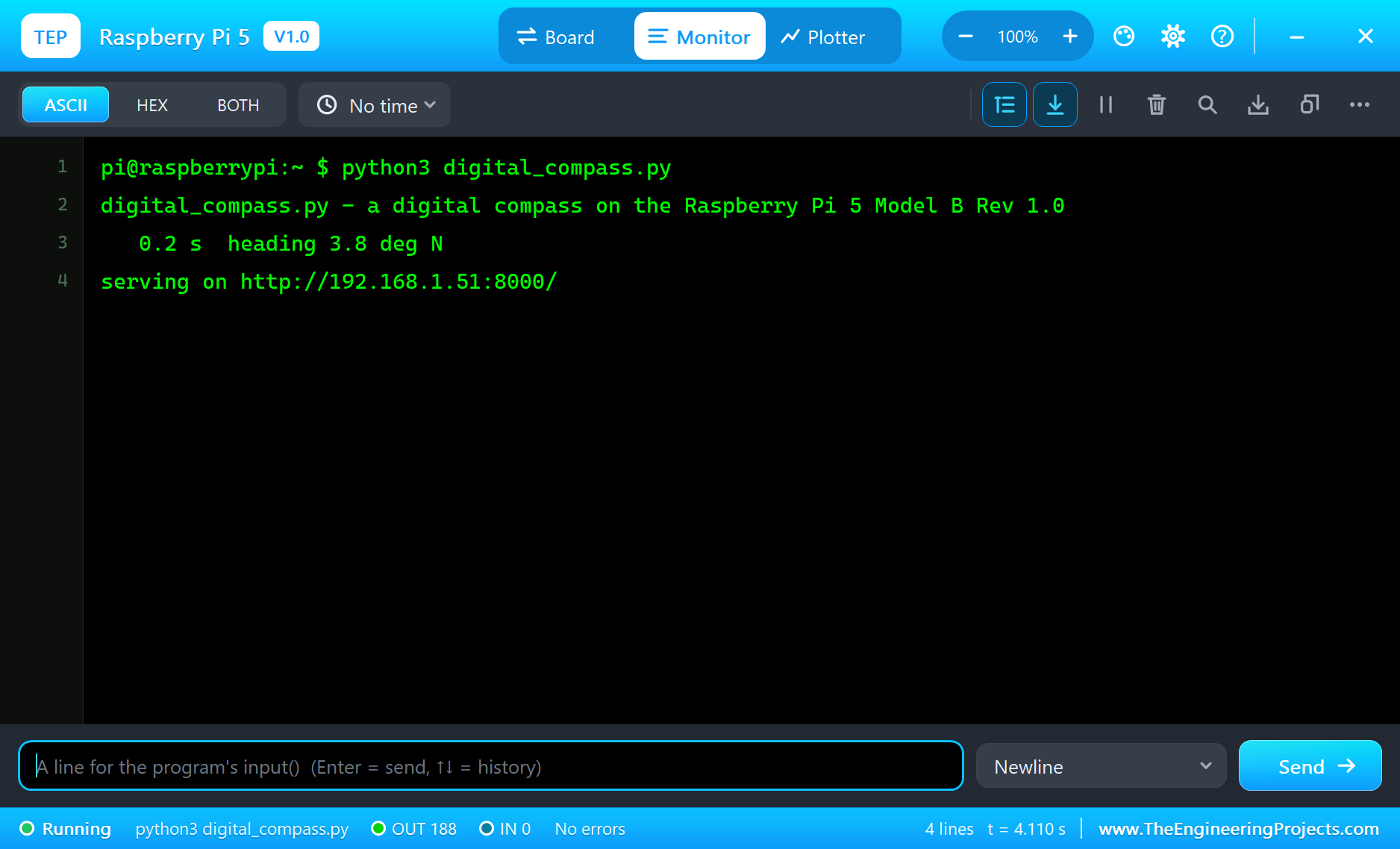
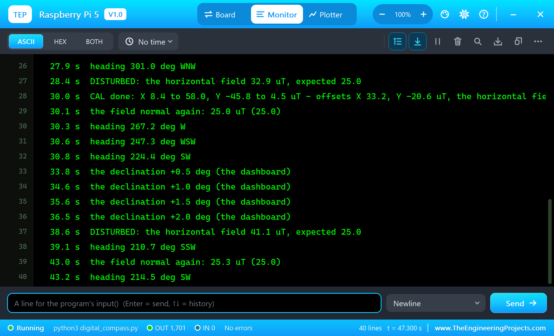
Here is the run that made the screenshots of this tutorial, 47.5 seconds of simulation. The times are the program's own, the seconds since it started, as it printed them in the Pi's terminal.
Pointing North
The program starts with the board pointing exactly north and reads 3.8 degrees N, with a horizontal field of 23.1 microtesla instead of 25. That is the chip's own small offsets at work, as in the worked example above: a real chip is never perfect. The TFT shows the card with N at the top, under the yellow mark, and the dashboard says NOT CALIBRATED.
Turning the Board: East and Southwest
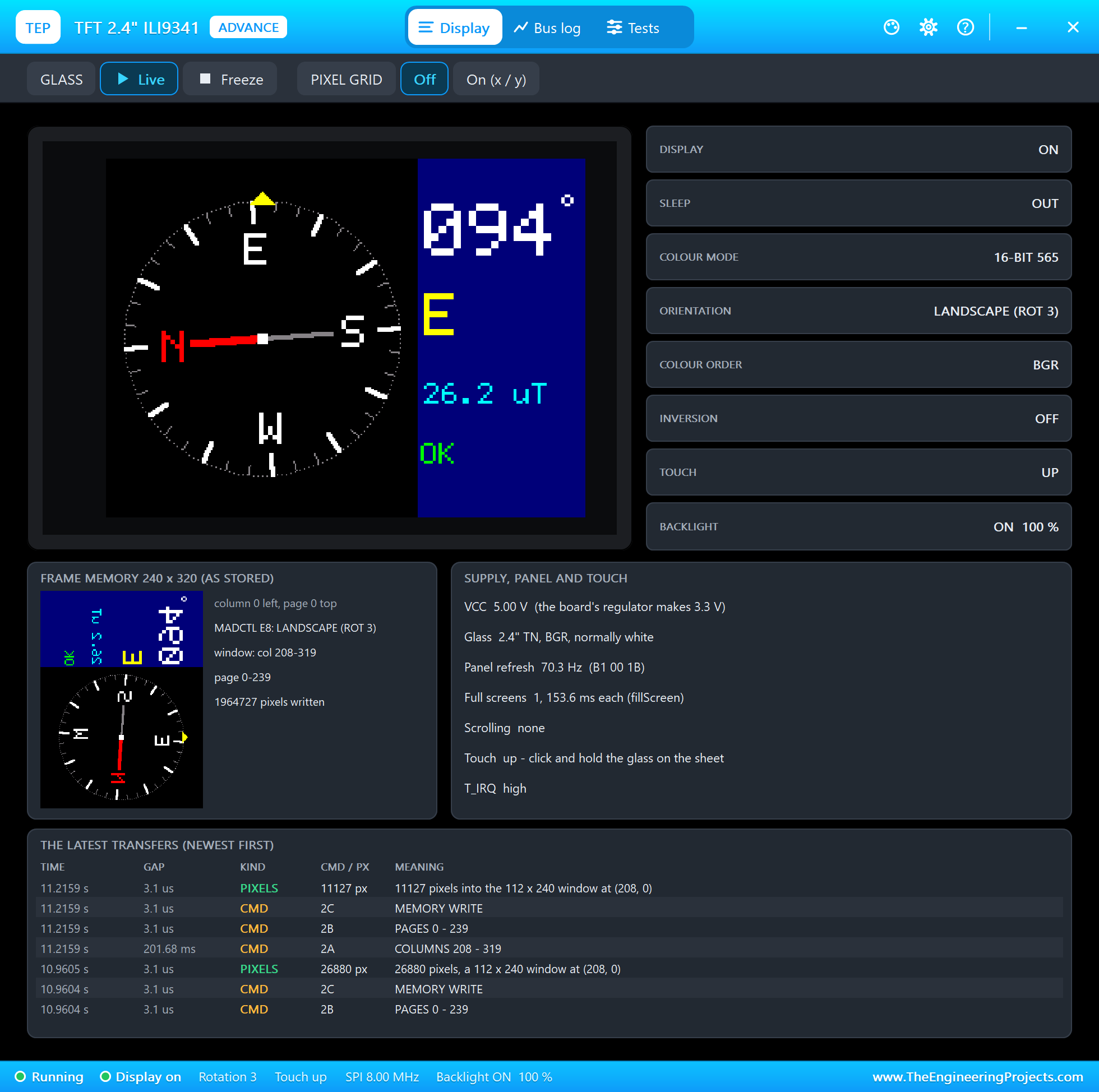
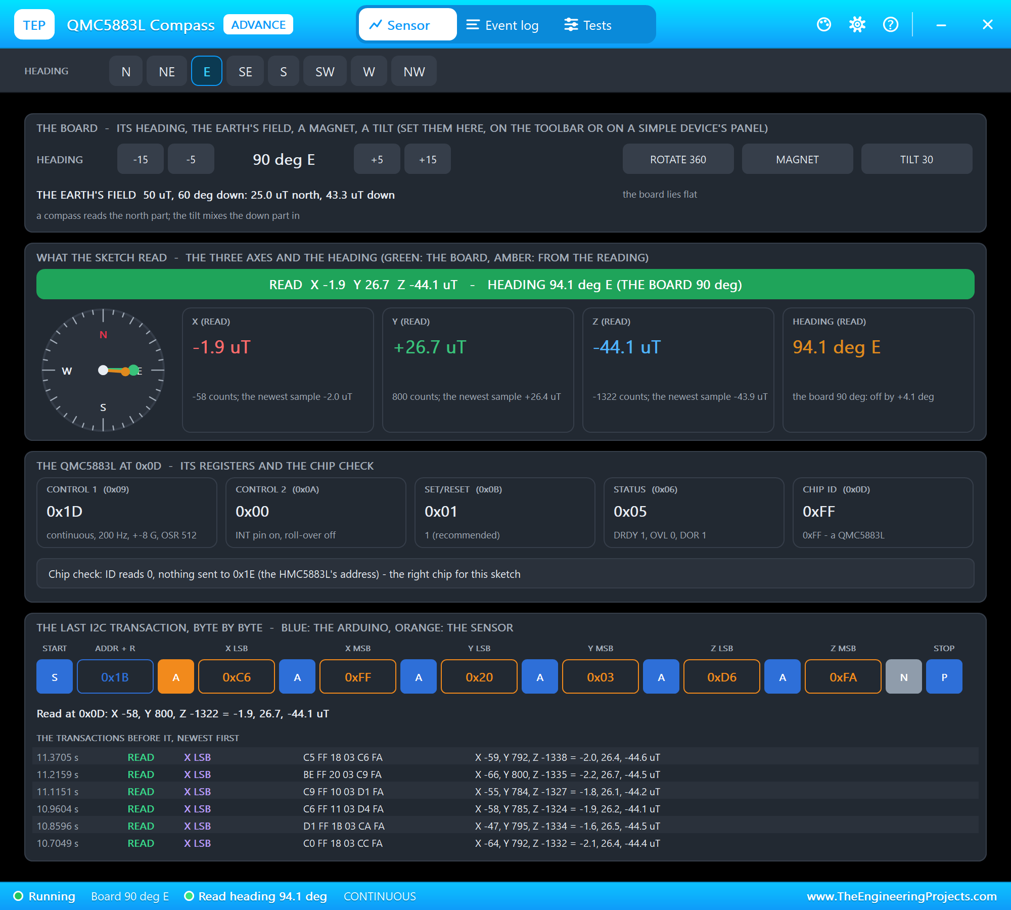
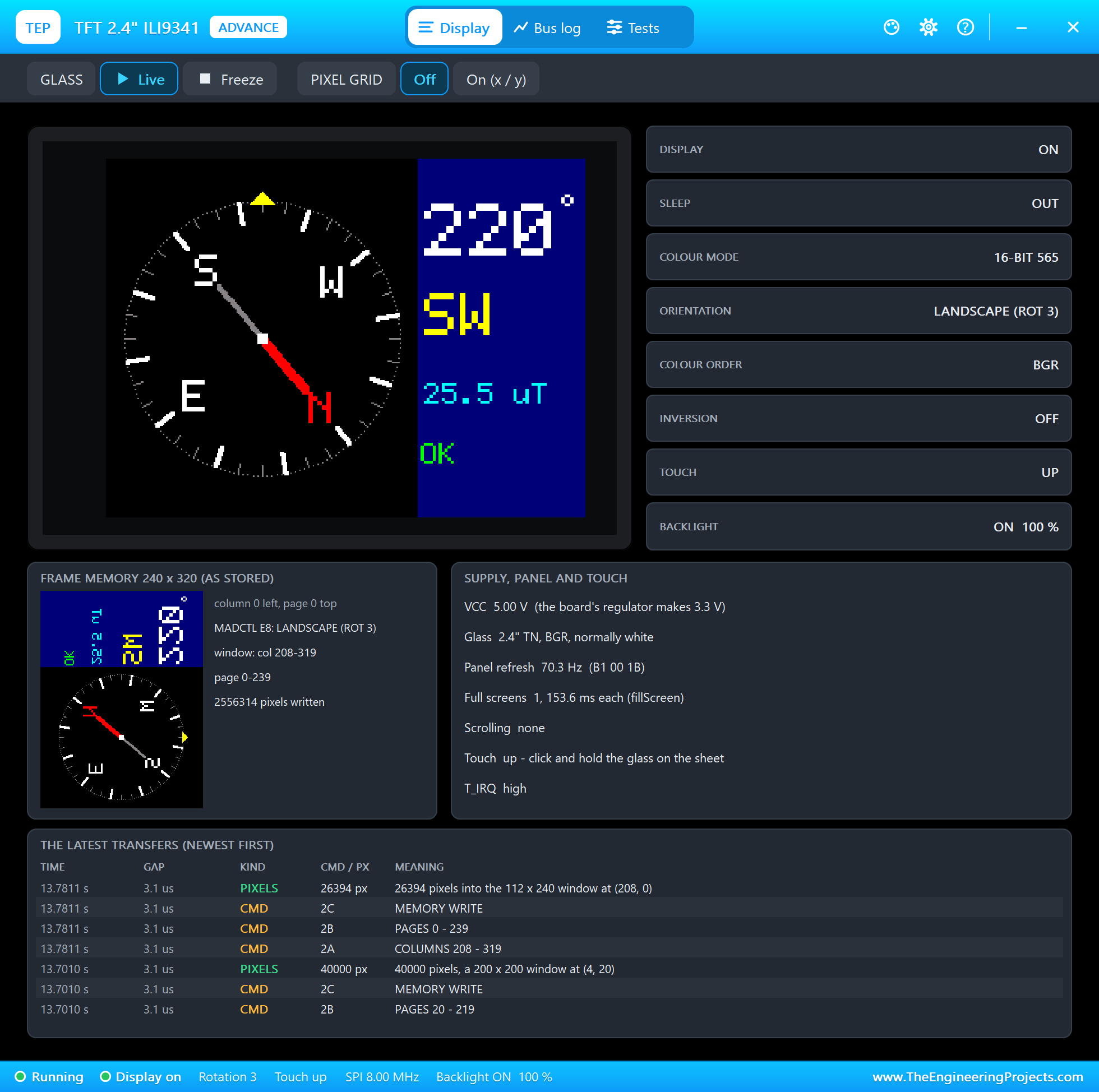
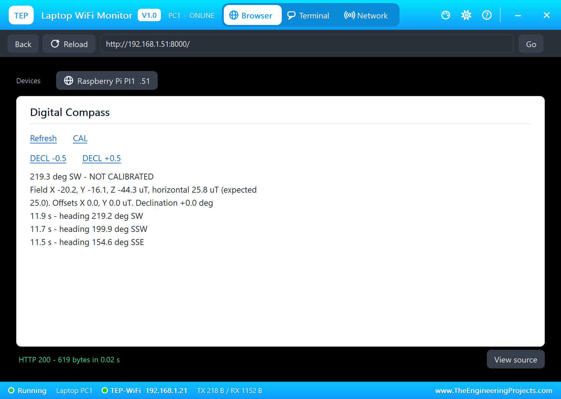
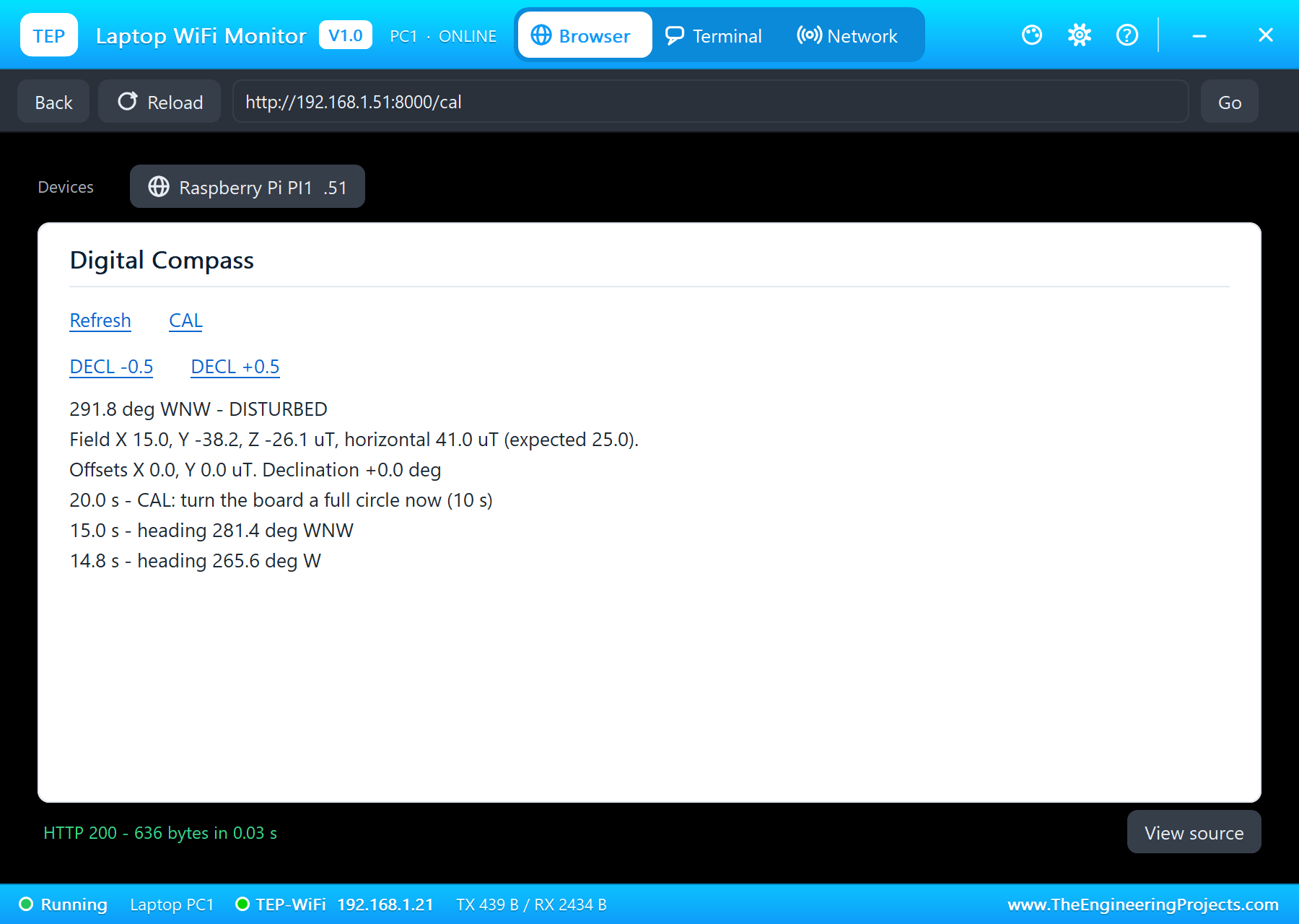
At 8.4 seconds the board turns to east in the GY-271's pop-up. The program follows it through NNE, NE and ENE to 94.3 degrees E, and the card turns the other way: N now points to the left of the screen, because magnetic north is on the board's left when it faces east. At 11.9 seconds the board faces southwest and the heading reads 219.2 degrees SW. Without a calibration, the chip's offsets still cost a few degrees.
A Magnet on the Board
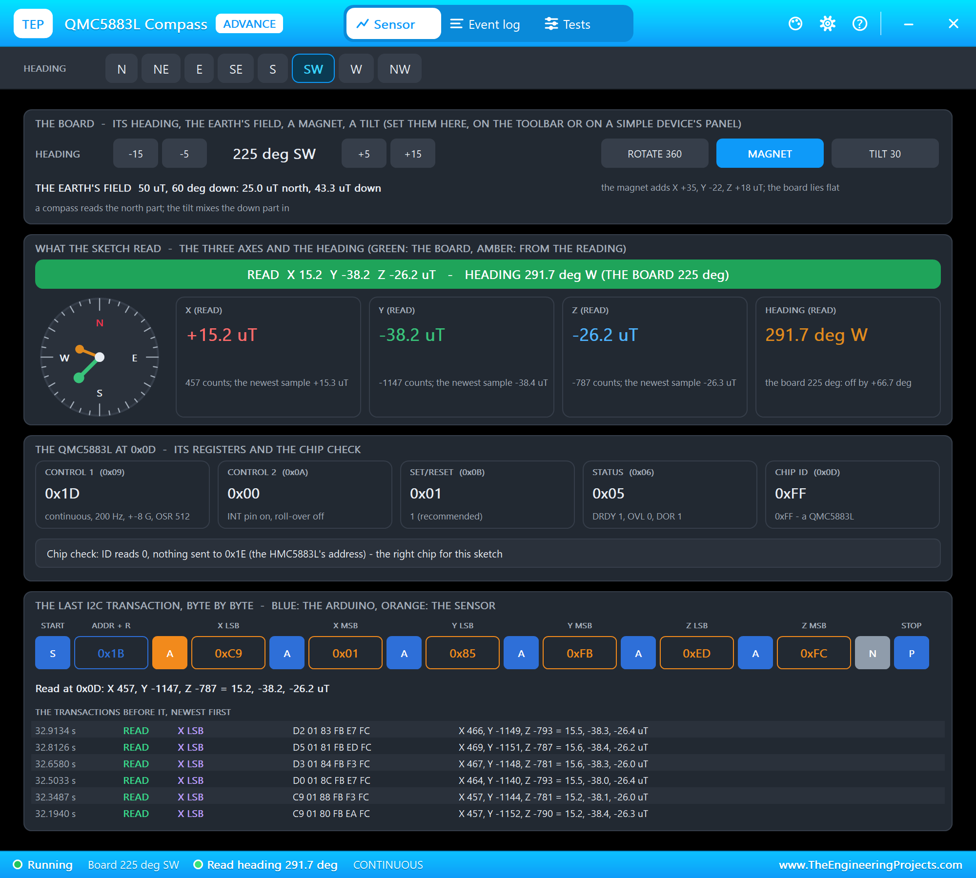
At 14.5 seconds a magnet goes on the board, fixed to it like a speaker or a steel screw would be. The pop-up shows what it adds: X +35, Y -22 and Z +18 microtesla, more than the Earth's own horizontal field. The heading jumps to 291.8 degrees WNW although the board still faces southwest, 67 degrees off, and the program prints "DISTURBED: the horizontal field 41.6 uT, expected 25.0". The screen and the dashboard both turn red.
The Calibration Turn
At 20 seconds CAL on the laptop starts a 10-second calibration, and ROTATE 360 in the pop-up turns the board a full circle in 8 seconds. Watch the heading during the turn: it does not go round, it swings from 304 to 351 degrees, back to 301, and so on. That is what a strong hard-iron offset does: the circle of readings is shifted so far that it no longer surrounds zero, and atan2 only sweeps part of the compass. The program does not care: it only keeps the lowest and the highest X and Y.
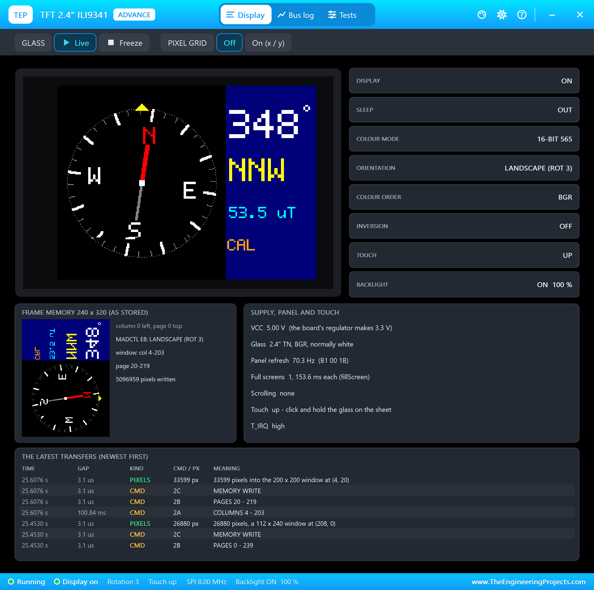
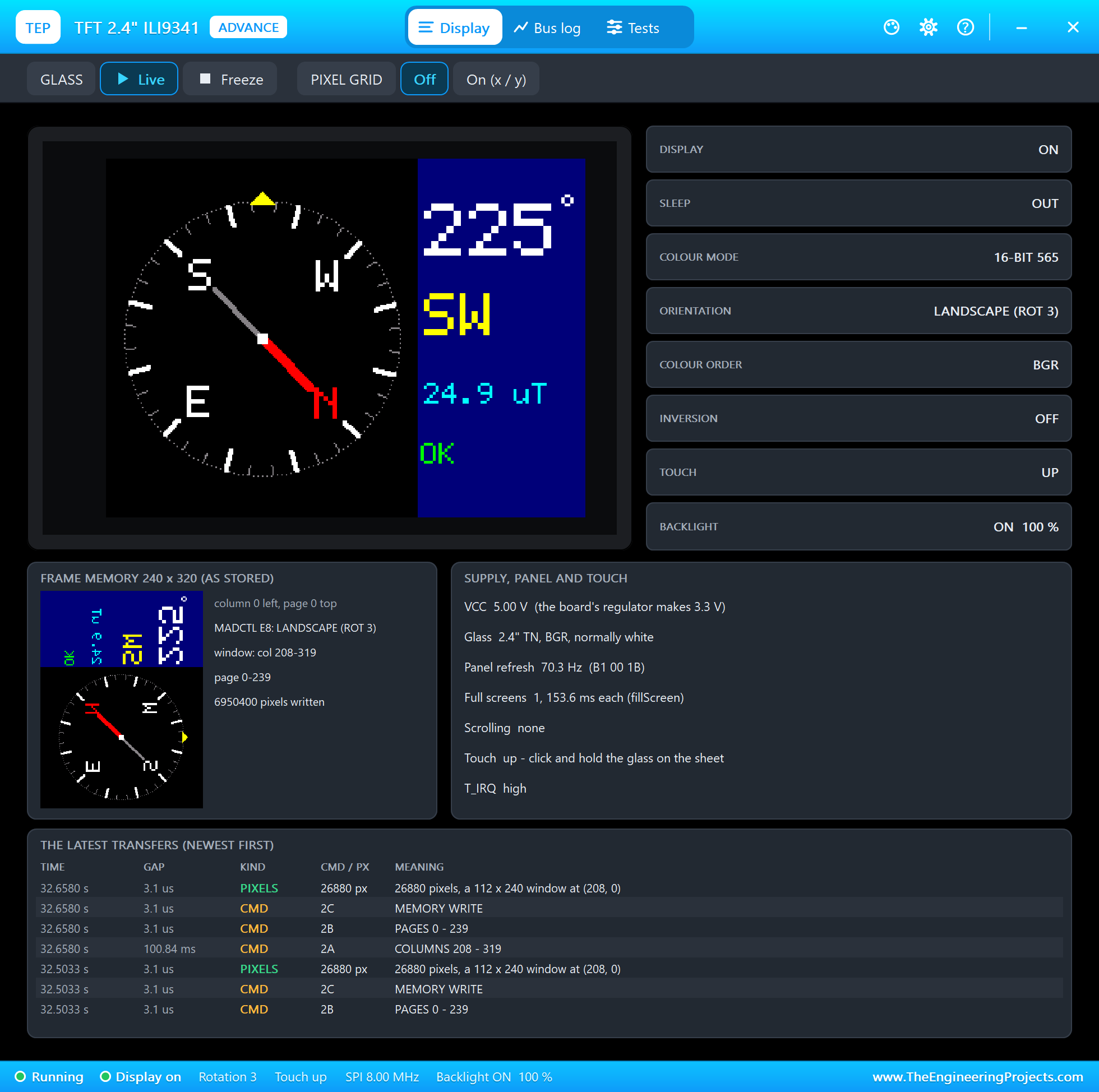
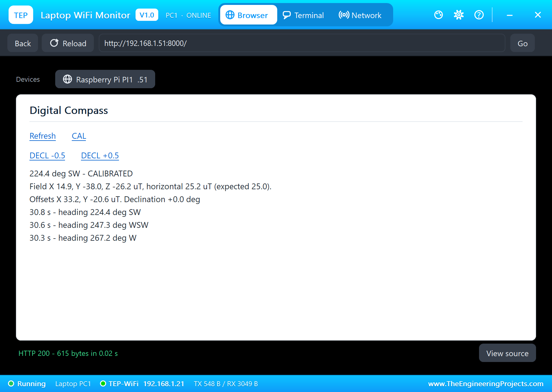
At 30 seconds: "CAL done: X 8.4 to 58.0, Y -45.8 to 4.5 uT - offsets X 33.2, Y -20.6 uT, the horizontal field 25.0 uT". The offsets are the magnet's +35 and -22 plus the chip's own small offsets, and half the range gives exactly the Earth's 25 microtesla. With the magnet still on the board, the heading now reads 224.4 degrees SW: the board faces 225 degrees.
The Declination
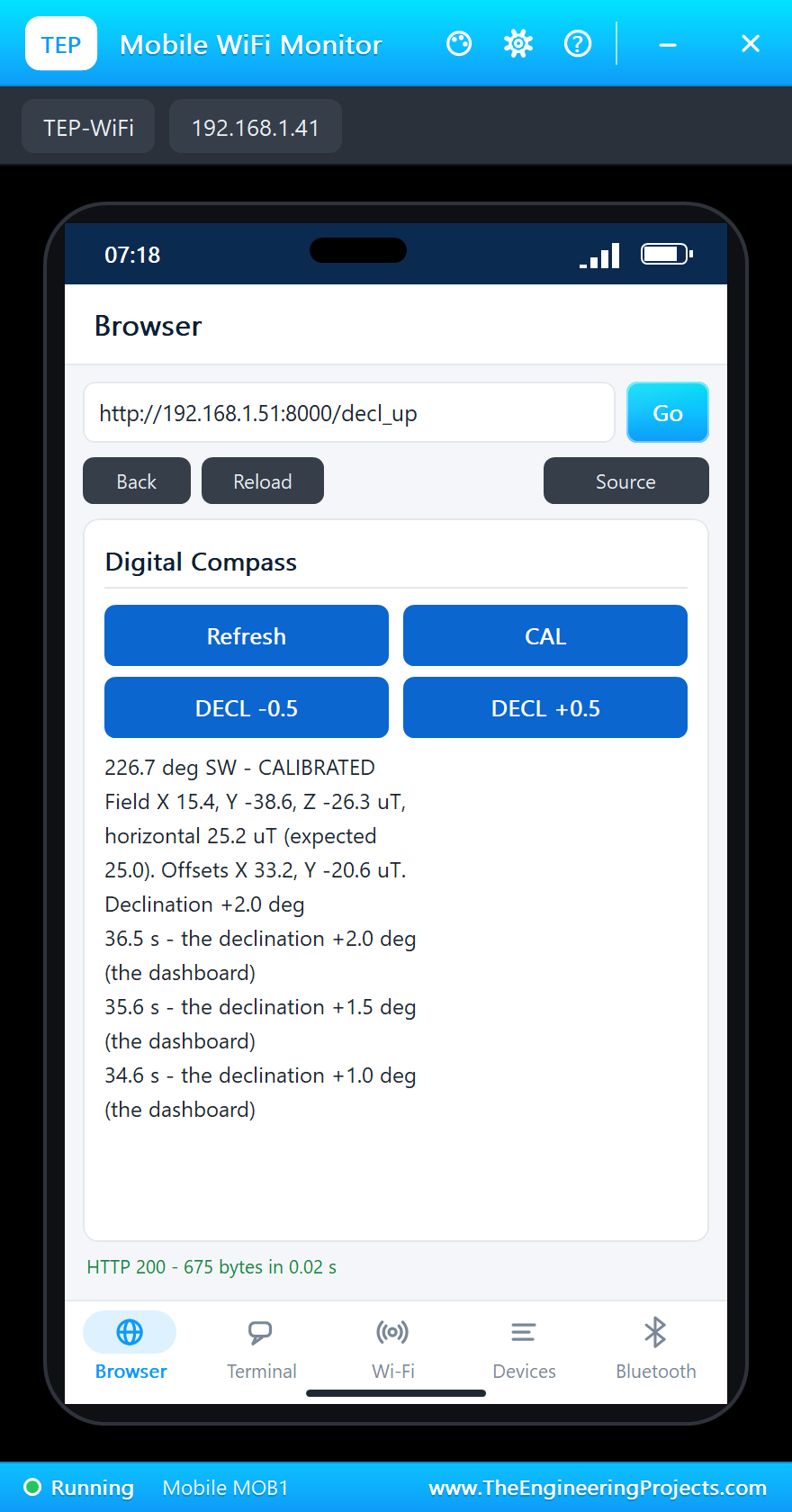
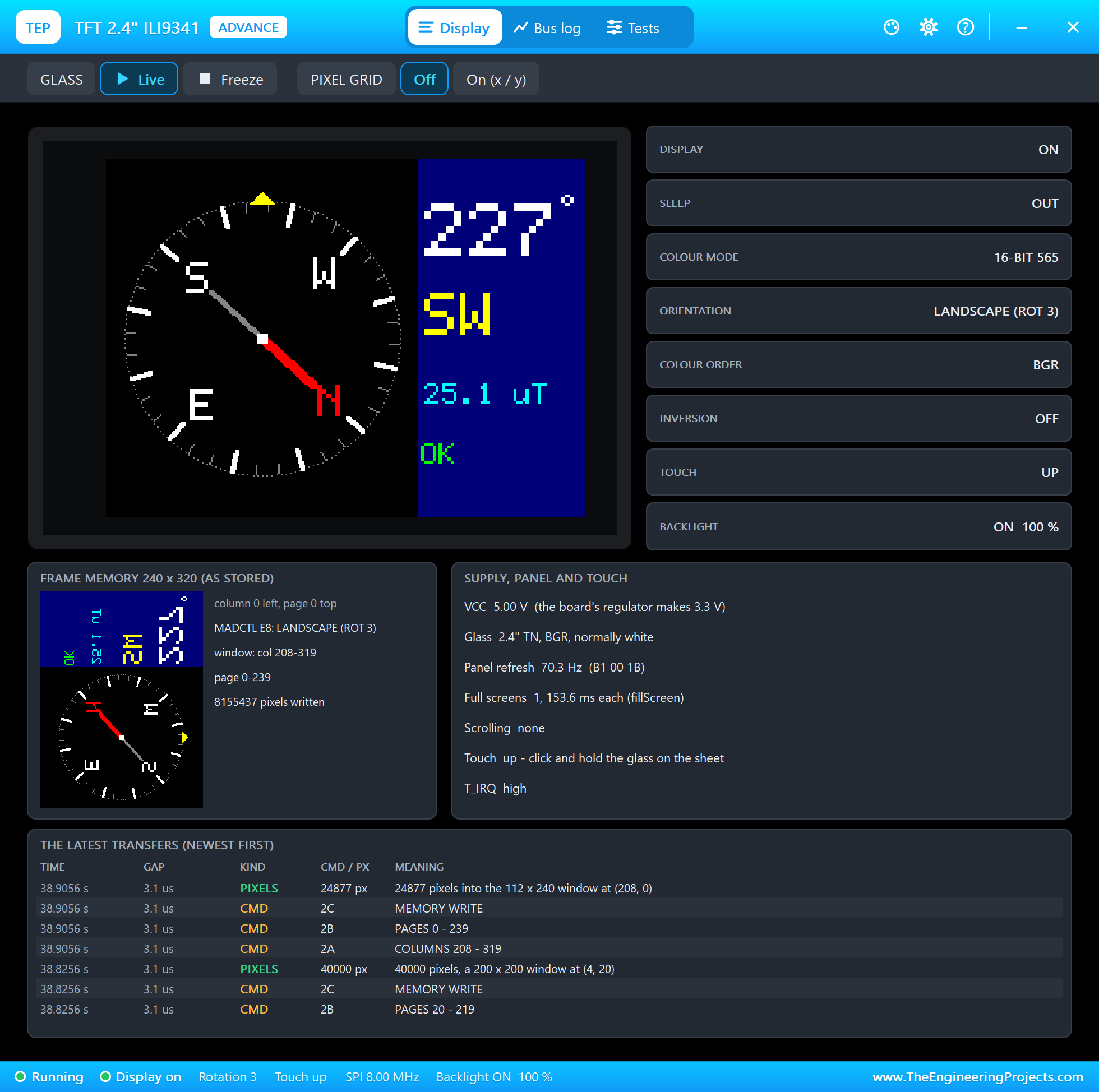
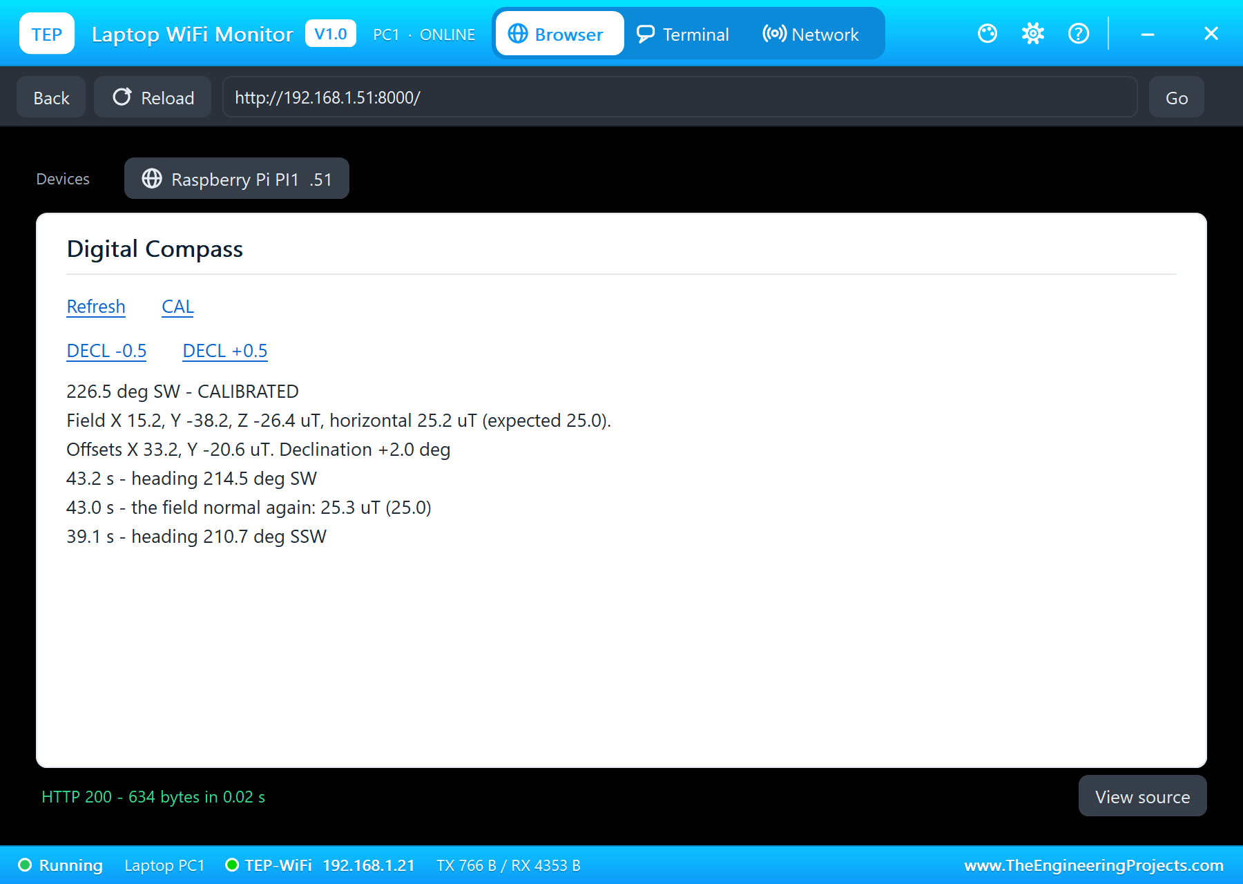
From 33.8 seconds, DECL +0.5 on the phone four times sets the declination to +2.0 degrees, as for a town where magnetic north lies 2 degrees east of true north. The heading moves from 224.4 to 226.5 degrees: it now gives the direction from true north.
Tilting the Board
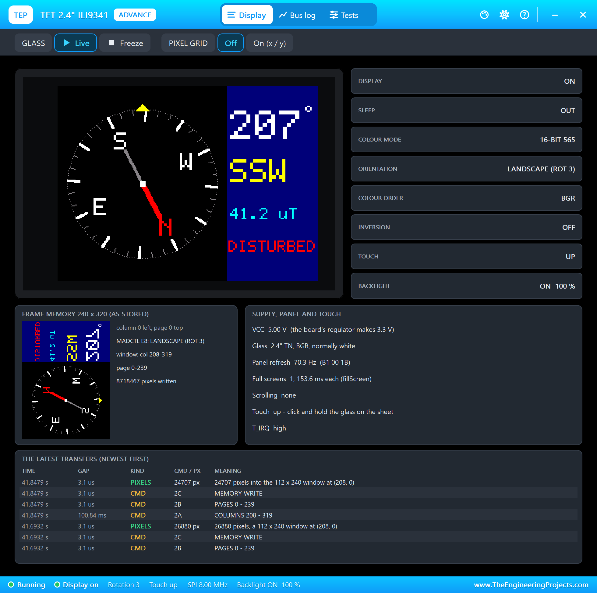
At 38.6 seconds TILT 30 tilts the board by 30 degrees. Part of the Earth's strong downward field now falls on the chip's X and Y axes: the horizontal field reads 41.1 microtesla and the heading 207.2 degrees SSW, 20 degrees wrong. The program cannot correct it, but it notices it: DISTURBED. This is why phones combine the magnetometer with an accelerometer that knows which way is down. At 43 seconds the board lies flat again, the field is normal, and the heading is back to 226.5 degrees SW.
The Numbers of the Run
| What | Result |
|---|---|
| North, before a calibration | 3.8 degrees, horizontal 23.1 microtesla |
| East / southwest | 94.3 / 219.2 degrees |
| The magnet (X +35, Y -22, Z +18 uT) | 291.8 degrees with the board at 225, DISTURBED at 41.6 microtesla |
| Calibration | offsets X 33.2, Y -20.6 microtesla, field 25.0; then 224.4 degrees |
| Declination +2.0 degrees | 226.5 degrees |
| Tilt 30 degrees | 207.2 degrees, DISTURBED at 41.1 microtesla |
| The TFT | MADCTL E8 (landscape), SPI at 8 MHz, 8,155,437 pixels written |
| Simulation | 47.5 s of simulation |
Download the Project Files
Click the button below to download IoT-Digital-Compass-Raspberry-Pi-5-Proteus-Simulation-v1.0.zip (about 13.4 MB, without the source code of the models):
IoT Digital Compass with Raspberry Pi 5 - Proteus Simulation V1.0- Proteus Simulation: Pi-5-Digital-Compass.pdsprj, the program digital_compass.py and copies of the models.
- Python Code: digital_compass.py, the complete program.
- Proteus Library Files: the LIB files of the Raspberry Pi 5, the GY-271, the ILI9341 and the two WiFi Monitors.
- Proteus Model Files: the DLL models and the TEPPi folder, the Python 3.11 and the runtime that the Pi board runs.
- README.txt: the installation steps, the properties, the test results and the links to every library post.
No Proteus yet? Read How to Download and Install Proteus 7 and 8. New to libraries? Follow How to Install a New Library in Proteus.
How to Install the Project Files
- Close Proteus and extract the whole zip file, for example to your Desktop.
- Copy the files from Proteus Library Files into the LIBRARY folder of Proteus.
- Copy everything in Proteus Model Files, the DLL files and the TEPPi folder, into the MODELS folder.
- Start Proteus and open the project from the Proteus Simulation folder.
Changing the Code
The program is plain Python 3: edit digital_compass.py beside the project and press Play again; the Pi board runs the new file. The calibration time, the disturbance limit and the colours are at the top. The same program runs on a real Raspberry Pi 5 with Raspberry Pi OS, lgpio and spidev; enable I2C and SPI in raspi-config. For our other Raspberry Pi 5 project with an I2C chip and smooth graphics on the sheet, see the IoT Robot Arm Controller with Raspberry Pi 5.
Ideas to Extend the Project
- Add an accelerometer, such as an MPU-6050, and compensate the tilt as phones do.
- Save the calibration to a file, so the compass starts calibrated.
- Add soft-iron calibration: scale each axis so the circle of readings is a true circle.
- Show a course to steer: set a target heading on the dashboard and draw an arrow towards it.
- Add a GPS module and point to a waypoint.
- Use the TFT's touch screen to start the calibration.
From Simulation to Real Hardware
- Keep it away from steel and magnets: speakers, motors, screws and even the TFT's backlight current pull a compass; mount the sensor a few centimetres away.
- Calibrate in place: calibrate with the sensor mounted where it will work, with everything around it.
- Find your declination: look it up for your town; it changes slowly over the years.
- Check the chip: many GY-271 boards sold as HMC5883L carry a QMC5883L at 0x0D; run i2cdetect to see which one you have.
- Mind the axes: the board's printed X arrow is the axis the heading is measured along.
Troubleshooting
- No reading, an I2C error: SDA and SCL swapped, or the chip is an HMC5883L at 0x1E.
- The heading swings unevenly as the board turns: hard iron; run CAL with a full turn.
- DISTURBED all the time: a magnet near the sensor after the calibration, or the board tilted.
- The TFT stays dark: no power on VCC or LED, or RESET held low.
- A garbled picture: the SPI clock above 10 MHz, or DC and CS swapped.
- The terminal cannot start Python: the TEPPi folder is not in MODELS.
Limitations of the Simulation
- The field comes from the GY-271's pop-up: an ideal Earth's field, one magnet and one tilt angle.
- There is no tilt compensation: without an accelerometer, a tilted compass reads wrong, in the simulation as in real life.
- The network is simulated: the dashboard travels between the Pi and the two monitors inside Proteus; the times in this tutorial are simulation time.
- Raspberry Pi is a trademark of Raspberry Pi Ltd; the QMC5883L is made by QST and the ILI9341 by Ilitek. This project is not made or endorsed by them or by Labcenter.
So, that was all about the IoT Digital Compass with Raspberry Pi 5 - Proteus Simulation. I hope it helps you build your own compass: a magnetometer on I2C, the heading from atan2, a calibration turn that removes the magnets around it, the declination, and a turning compass card drawn on a TFT from frame buffers, all tested in a simulation before you solder a wire. More IoT projects with the ESP32 and the Raspberry Pi 5 are coming in this series. If you have any questions, ask in the comments and I will help you out. Till the next tutorial, take care and have fun!