Hello friends, I hope you all are doing great. Today, I am going to share the IoT Robot Arm Controller with Raspberry Pi 5 - Proteus Simulation, the twenty-eighth project of our IoT Projects series. If you have searched for a Proteus simulation of a Raspberry Pi robot arm with a PCA9685 servo driver, here is a complete one. A Raspberry Pi 5 drives a 4-DOF desktop robot arm with four SG90 servos through a PCA9685 16-channel PWM driver on I2C. The program works out the joint angles for any point the claw should reach, moves every joint smoothly, picks up a block and places it on a second stand, jogs the claw up, down, out and in by millimetres, records poses and plays them back, all from a web dashboard on a laptop or a phone.
Robot arms do the welding, the painting and the packing in factories, and a small arm on four hobby servos teaches the same ideas on a desk. In this tutorial, we will go through the circuit, learn how a hobby servo reads its pulse, program the PCA9685's 12-bit PWM counter over I2C, work out where the claw is from the joint angles (forward kinematics) and the joint angles for a point (inverse kinematics), move the joints smoothly, build a pick-and-place sequence, walk through the Python program, and then run the simulation: the home pose, a complete pick and place, jogging the claw until it is out of reach, teaching three poses and playing them back, and an emergency STOP with the block in the claw. At the end, you can download the project with the program, every library file and the Python runtime the Pi needs.
NOTICE: Our team has put a lot of effort into this project: the circuit, the code and every part in the simulation are our own work, and you get them all free. Your feedback is the fuel that keeps us going, so please tell us what you think in the comments below. And if our free projects help you, you can buy us a coffee. So, let's get started with the IoT Robot Arm Controller with Raspberry Pi 5 - Proteus Simulation:
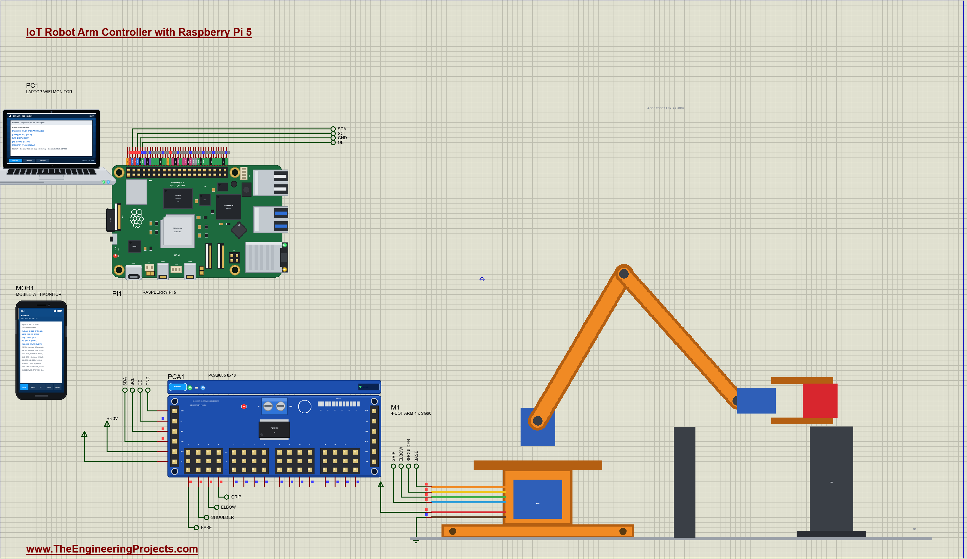
What Does This Robot Arm Controller Do?
- Four joints on one I2C bus: BASE, SHOULDER, ELBOW and GRIP, four SG90 servos on the PCA9685's channels 0 to 3.
- Knows where its claw is: forward kinematics turns the joint angles into millimetres out and up.
- Reaches a point: inverse kinematics turns millimetres into joint angles, and refuses a point out of reach.
- Moves smoothly: every joint at 60 degrees a second, 50 small steps a second, inside its limits.
- Pick and place: carries a block between two stands, straight ahead and 60 degrees to the left.
- Teach and repeat: RECORD up to eight poses, PLAY them back in order.
- A dashboard with STOP: HOME, PICK AND PLACE, LEFT, RIGHT, UP, DOWN, OUT, IN, OPEN, CLOSE, RECORD, PLAY and an emergency STOP.
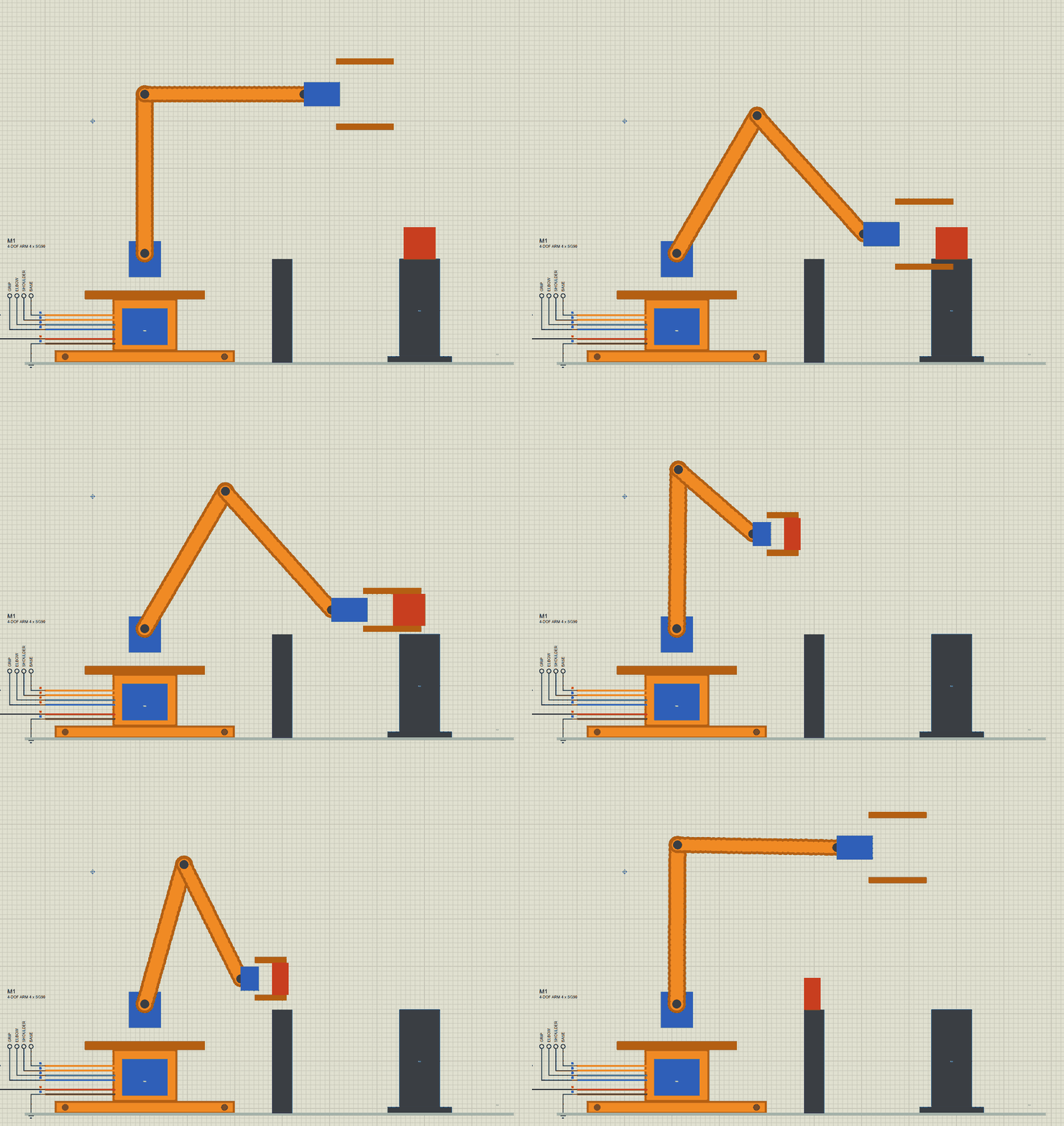
It is a great first robotics project and a practical lesson in I2C, PWM registers, servo timing and the geometry of an arm. In the simulation, the arm moves on the Proteus sheet at true scale, drawn from the side, and its pop-up shows the arm from the side and from the top with the stands and the block.
Components Used in the Proteus Simulation
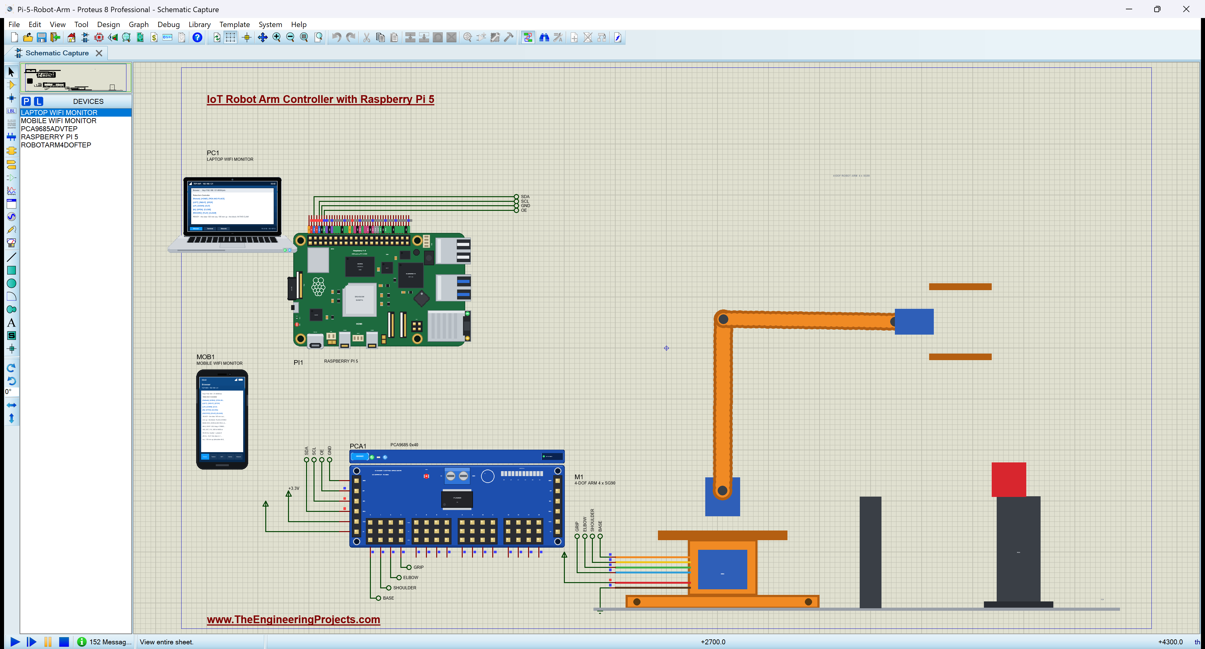
All the parts come from our Proteus libraries, each with its own tutorial. The project zip at the end includes every LIB and DLL file.
| Part | Proteus device | Library post | Connection |
|---|---|---|---|
| Raspberry Pi 5 | RASPBERRY PI 5 | Raspberry Pi 5 Library for Proteus | PI1, Ethernet 192.168.1.51 |
| PCA9685 16-channel servo driver | PCA9685ADVTEP | PCA9685 Servo Driver Library for Proteus | PCA1, I2C1 at 0x40 |
| 4-DOF robot arm (four SG90 servos) | ROBOTARM4DOFTEP | 4-DOF Robot Arm Library for Proteus | M1, on PWM0 - PWM3 |
| Laptop WiFi Monitor | LAPTOP WIFI MONITOR | Laptop WiFi Monitor | PC1 |
| Mobile WiFi Monitor | MOBILE WIFI MONITOR | Mobile WiFi Monitor | MOB1 |
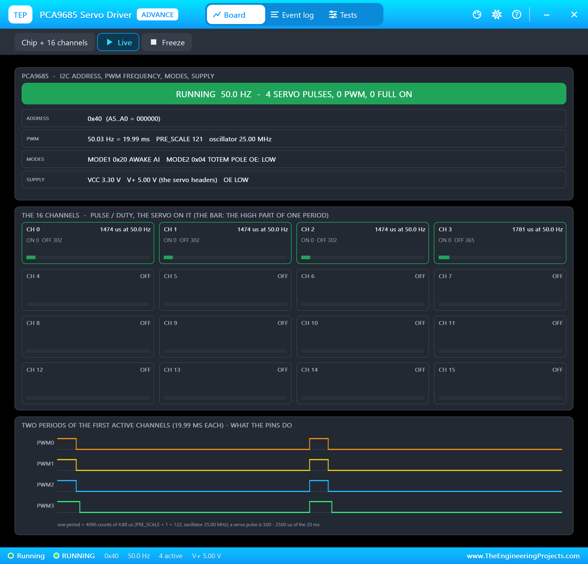
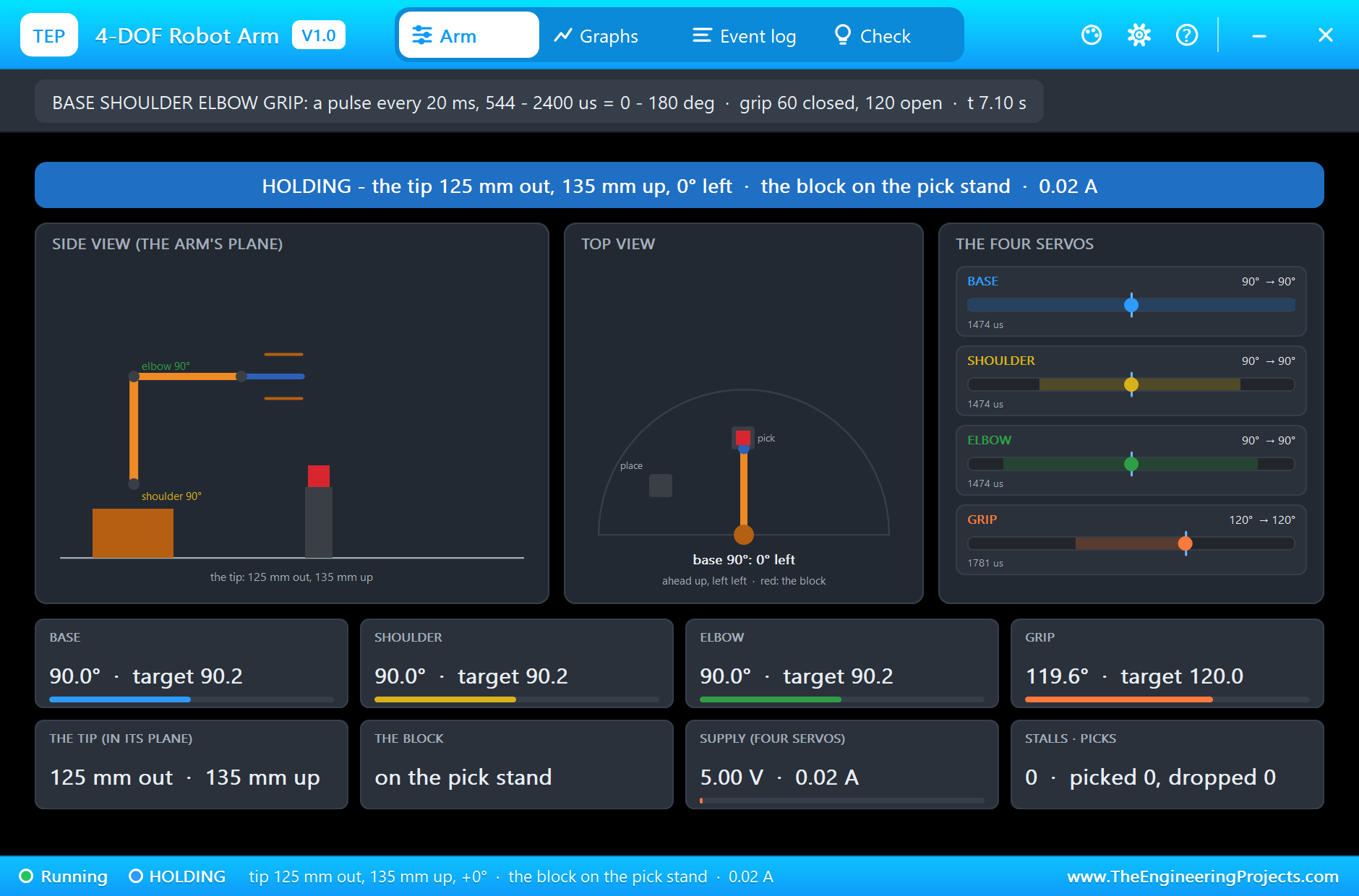
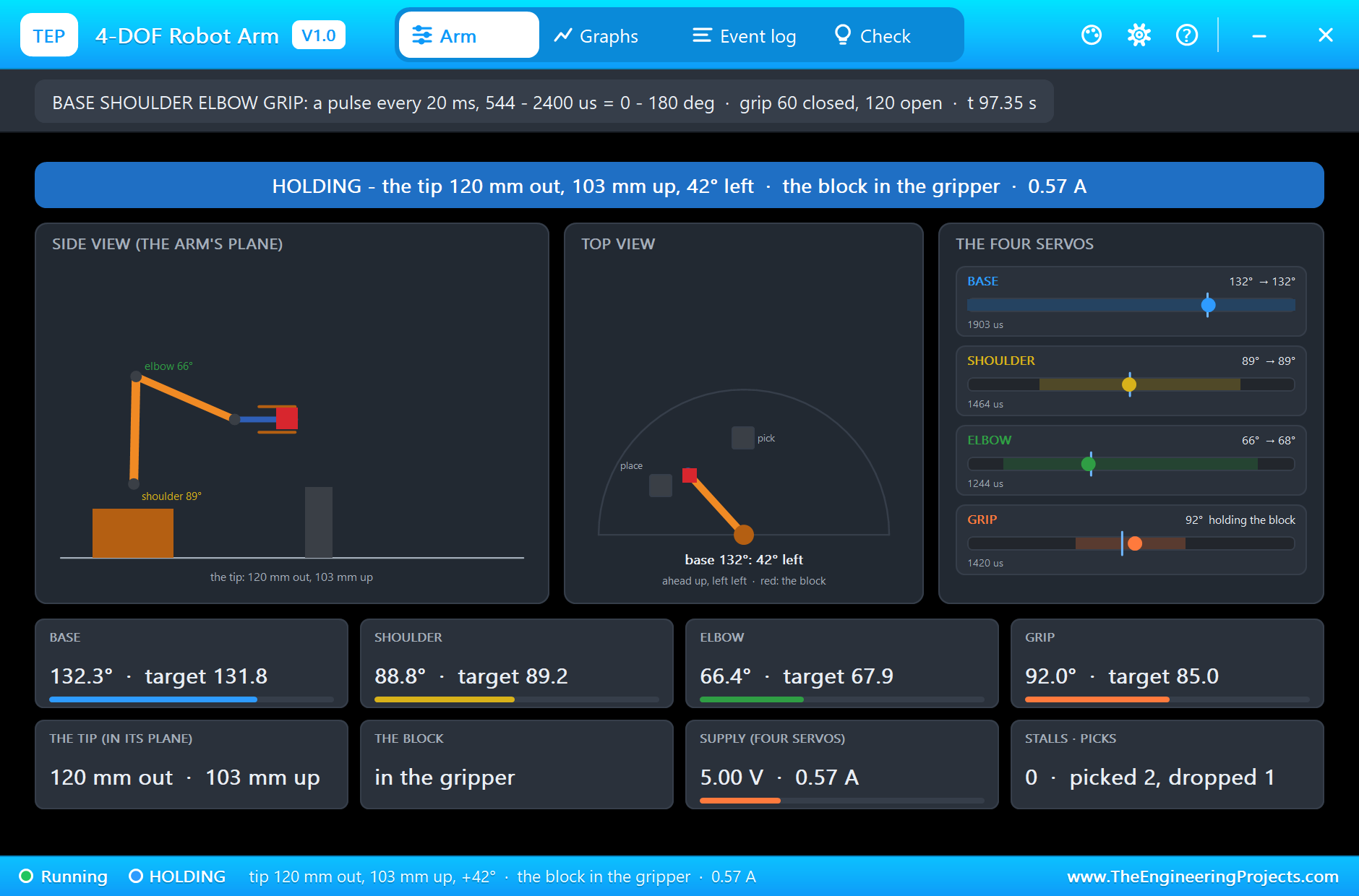
The PCA9685 and the arm are models with pop-ups. The PCA9685's pop-up shows the I2C address, the PWM frequency and the prescaler, the two mode registers, the supplies, all 16 channels with their pulse widths and counts, and two periods of the active channels as a timing diagram. The arm's pop-up shows the arm from the side in its own plane and from the top with the two stands and the block, the four servos with their limits, graphs, an event log and a check page.
Proteus Simulation of the Robot Arm: the Circuit

| Part | Pins | Connection |
|---|---|---|
| PCA1 PCA9685 | SDA / SCL / OE / GND | SDA1 GPIO2 (pin 3) / SCL1 GPIO3 (pin 5) / GPIO4 (pin 7) / GND (pin 6) |
| PCA1 PCA9685 | VCC / V+ | 3.3 V (the logic) / the 5 V supply (the servos) |
| M1 robot arm | BASE / SHOULDER / ELBOW / GRIP | PWM0 / PWM1 / PWM2 / PWM3 of the PCA9685 |
| M1 robot arm | V+ / GND | the 5 V supply / GND |
Why a PCA9685 and not the Pi's own pins? A servo wants a pulse every 20 ms with an exact width, and Linux on the Pi can delay a program for a few milliseconds whenever it is busy, which makes a servo twitch. The PCA9685 makes 16 pulse trains in hardware from its own 25 MHz oscillator; the Pi only writes a new number for a channel when a joint moves. Its VCC takes 3.3 V, so its I2C pull-ups keep SDA and SCL at the Pi's 3.3 V levels; in the simulation a +3.3V power terminal stands for the Pi's 3.3 V pin, because the Pi model's supply pins are digital. V+ feeds the servos from the 5 V supply, and OE, output enable, switches all 16 outputs off while it is high.
How the Robot Arm Works
How a Hobby Servo Reads Its Pulse
A hobby servo is a small motor, a gearbox and a potentiometer on the output shaft, with a controller that compares the shaft's angle with the pulse it receives. The pulse comes every 20 ms, 50 times a second, and its width sets the angle. The SG90s in this arm take 544 to 2,400 microseconds for 0 to 180 degrees, the range the Arduino Servo library uses. Worked example: 90 degrees is 544 + (2,400 - 544) x 90 / 180 = 1,472 microseconds.
The PCA9685's 12-bit PWM Counter
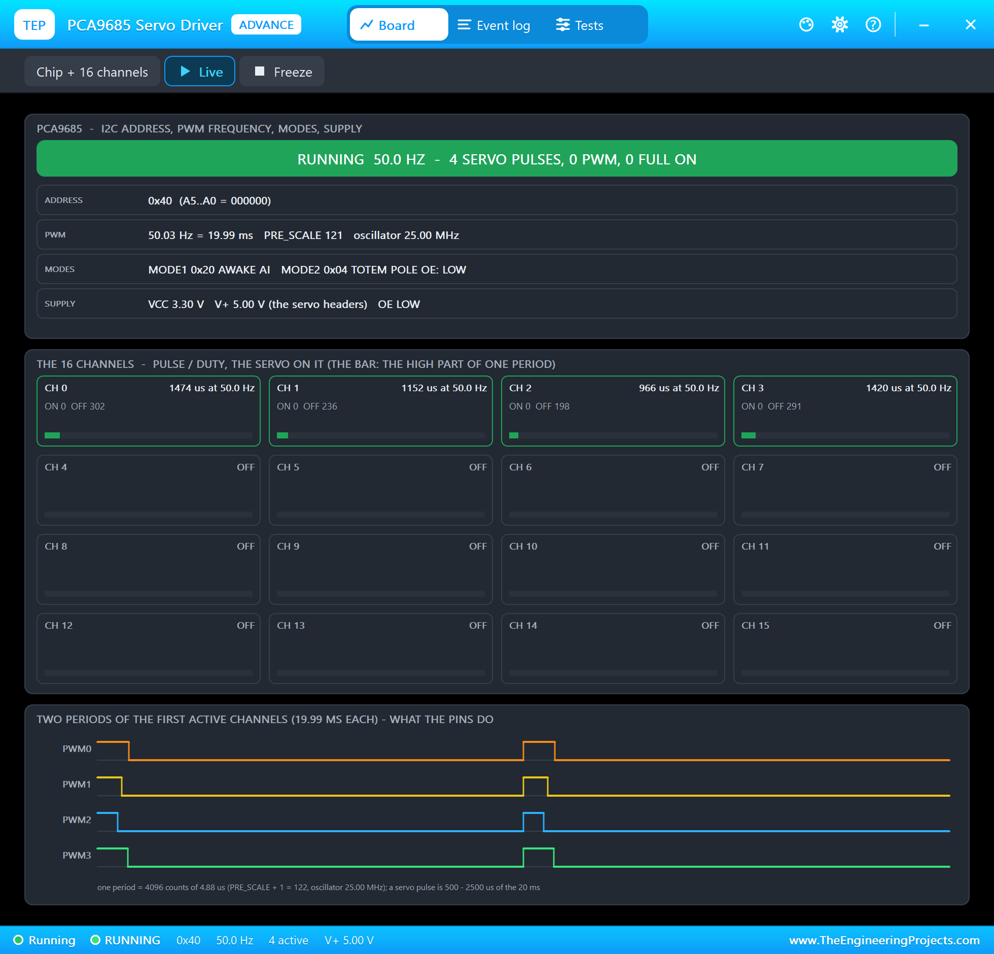
Inside the PCA9685 a 12-bit counter runs from 0 to 4,095 in every period, clocked by its 25 MHz oscillator through a prescaler. Each channel has an ON count, where its output goes high, and an OFF count, where it goes low again. The prescaler sets the frequency: PRE_SCALE = round(25,000,000 / (4,096 x 50)) - 1 = 121, and the frequency it really makes is 25,000,000 / (4,096 x 122) = 50.03 Hz, a period of 19.99 ms, so one count is 4.88 microseconds. Worked example: 1,472 microseconds / 4.88 microseconds = 302 counts, and 302 counts are 1,474 microseconds, the width the PCA9685's pop-up showed for 90 degrees.
Each channel has four registers, ON low, ON high, OFF low and OFF high, starting at 0x06 for channel 0, four addresses a channel. With auto-increment switched on in MODE1, one I2C transfer writes all four. PRE_SCALE can be changed only while the chip sleeps, so the program starts it in this order: SLEEP, PRE_SCALE, MODE2 (totem-pole outputs), awake with auto-increment, 500 microseconds for the oscillator, then RESTART.
Where Is the Claw? Forward Kinematics
The arm stands on a turning base. Its shoulder pivot is 55 mm above the table, the upper arm and the forearm are 80 mm each, and the claw reaches 45 mm past the wrist. A parallel linkage, like the levers of a desk lamp, sets the forearm's angle from the elbow servo alone: ELBOW 90 degrees holds the forearm level whatever the shoulder does, and the claw always stays level. So the claw's position in the arm's plane is:
- out = 80 x cos(SHOULDER) + 80 x cos(ELBOW - 90) + 45 mm
- up = 55 + 80 x sin(SHOULDER) + 80 x sin(ELBOW - 90) mm
Worked example: the home pose, SHOULDER 90 and ELBOW 90, gives out = 0 + 80 + 45 = 125 mm and up = 55 + 80 + 0 = 135 mm. The BASE angle then turns that plane round the base's axis: 90 degrees is straight ahead, 150 degrees is 60 degrees to the left.
Which Angles Reach a Point? Inverse Kinematics
Going the other way is the interesting part. Take the wrist, 45 mm back from the claw's point and measured from the shoulder pivot; call its distance from the pivot d and its direction phi. The upper arm, the forearm and the line to the wrist make a triangle with two sides of 80 mm, so the upper arm leans alpha = acos(d / 160) above that line and the forearm the same alpha below it. SHOULDER = phi + alpha, and ELBOW = phi - alpha + 90.
Worked example: the block waits on its stand 139 mm out and 63 mm up. The wrist is then 94 mm out and 8 mm above the pivot: d = 94.3 mm, phi = 4.9 degrees, alpha = acos(94.3 / 160) = 53.9 degrees, so SHOULDER = 58.7 degrees and ELBOW = 41.0 degrees, exactly what the program printed in our run. A point is out of reach when d is longer than both arms, 160 mm, or when an angle would leave the joint's limits; the program keeps a margin inside the arm's mechanical stops: SHOULDER 45 to 145 and ELBOW 25 to 155 degrees.
Smooth Moves
A servo given a new angle jumps there as fast as its motor can, which shakes the arm and can throw the block out of the claw. So the program never sends the target at once: 50 times a second, each joint moves at most 1.2 degrees towards its target, 60 degrees a second, and only a joint that moved gets a new number over I2C. All four joints start and keep moving together, and a move of 30 degrees takes half a second.
Pick and Place, Step by Step
| Step | Joints | Why |
|---|---|---|
| open the claw | GRIP 120 | the jaws wide open |
| above the block | BASE to the stand, the claw 139 mm out, 100 mm up | come down from above, never through the stand |
| down to the block | 139 mm out, 63 mm up | the jaws around the 16 mm block |
| close the claw | GRIP 85 | the block stops the jaws near 92 degrees: a firm grip |
| lift the block | 120 mm out, 105 mm up | clear of the stand |
| turn | BASE to the other stand | 90 or 150 degrees |
| lower it, let go, up, home | 139 mm out, 65 mm up; GRIP 120; home | the block on the other stand |
Every position in the table is a point in millimetres, and the inverse kinematics turns it into angles. At every point the arm waits 0.4 seconds, the DWELL at the top of the program: the arm settles and the jaws finish closing or opening before the next move, as on an industrial pick-and-place robot. The next PICK AND PLACE carries the block back. If STOP freezes the arm while it holds the block, the next PICK AND PLACE finishes the move to the stand the block was going to.
The Python Code Explained
The whole program is included in the download. It uses lgpio for the I2C bus and the OE pin, the math module for the kinematics, threads for the motion and the sequences, and the standard library's http.server for the dashboard. At the top are the joints with their channels, their limits and their home angles:
JOINTS = [('BASE', 0, 0, 180, 90), ('SHOULDER', 1, 45, 145, 90), ('ELBOW', 2, 25, 155, 90), ('GRIP', 3, 60, 120, 120)]
H0, L1, L2, CLAW = 55.0, 80.0, 80.0, 45.0    # mm: the shoulder's height, the upper arm, the forearm, the claw past the wrist
The PCA9685
        self.prescale = round(osc / (4096 * hz)) - 1             # 25 MHz / (4096 x 50 Hz) - 1 = 121
        self.hz = osc / (4096 * (self.prescale + 1))             # the frequency it really makes: 50.03 Hz
        lgpio.i2c_write_byte_data(self.h, self.MODE1, 0x10)      # SLEEP: PRE_SCALE can be written only while the oscillator is off
        lgpio.i2c_write_byte_data(self.h, self.PRE_SCALE, self.prescale)
A pulse is one I2C block write of four bytes: ON at count 0, OFF at the count of the width:
        off = round(us * 4096 * self.hz / 1e6)
        lgpio.i2c_write_i2c_block_data(self.h, self.LED0_ON_L + 4 * ch, [0, 0, off & 0xFF, off >> 8])
At power-up the outputs stay off until every channel has its home pulse, so the servos do not jump:
lgpio.gpio_claim_output(chip, OE, 1) # outputs OFF until every channel has its home pulselgpio.gpio_write(chip, OE, 0) # now the servos get their pulses: no jump at power-upThe Kinematics
    s, f = math.radians(shoulder), math.radians(elbow - 90)     # the forearm's own angle (ELBOW 90 = level)
    return L1 * math.cos(s) + L2 * math.cos(f) + CLAW, H0 + L1 * math.sin(s) + L2 * math.sin(f)
dx, dz = out - CLAW, up - H0 # the wrist, from the shoulder pivot
d = math.hypot(dx, dz)
if d > L1 + L2 - 1 or d < 20:
return None alpha = math.acos((d * d + L1 * L1 - L2 * L2) / (2 * L1 * d)) # (law of cosines; L1 = L2 makes it acos(d / 160))The Motion Loop
                if d:
                    cur[k] = target[k] if abs(d) <= step else cur[k] + math.copysign(step, d)
                    ticks[k] = pca.pulse(j[1], angle_us(cur[k]))
The sequences run in their own thread, one at a time, so the web server always answers at once and STOP works in the middle of a move:
target[:] = cur # every joint stays where it isA jog that would leave the reachable area is refused before anything moves:
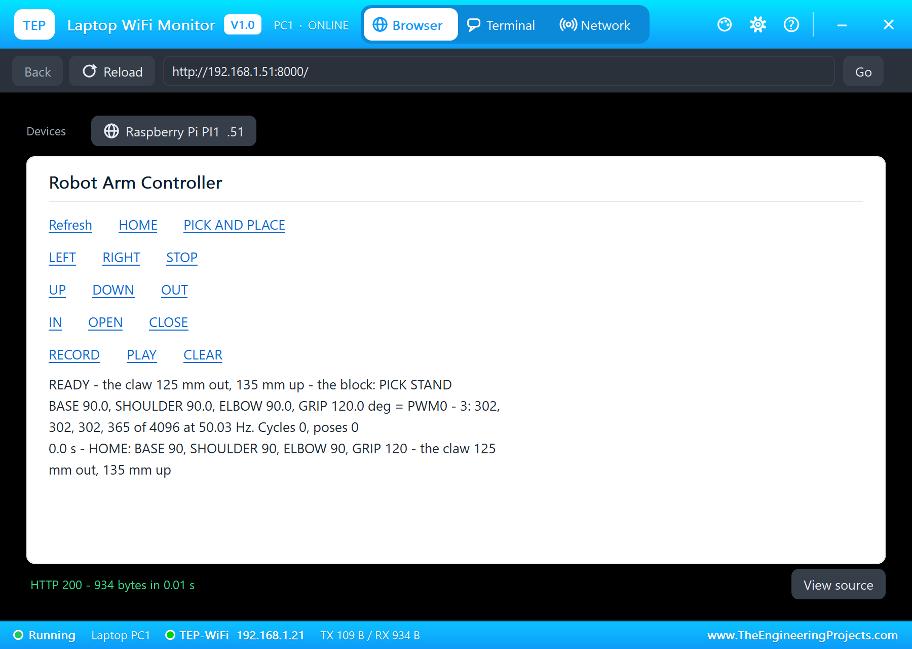
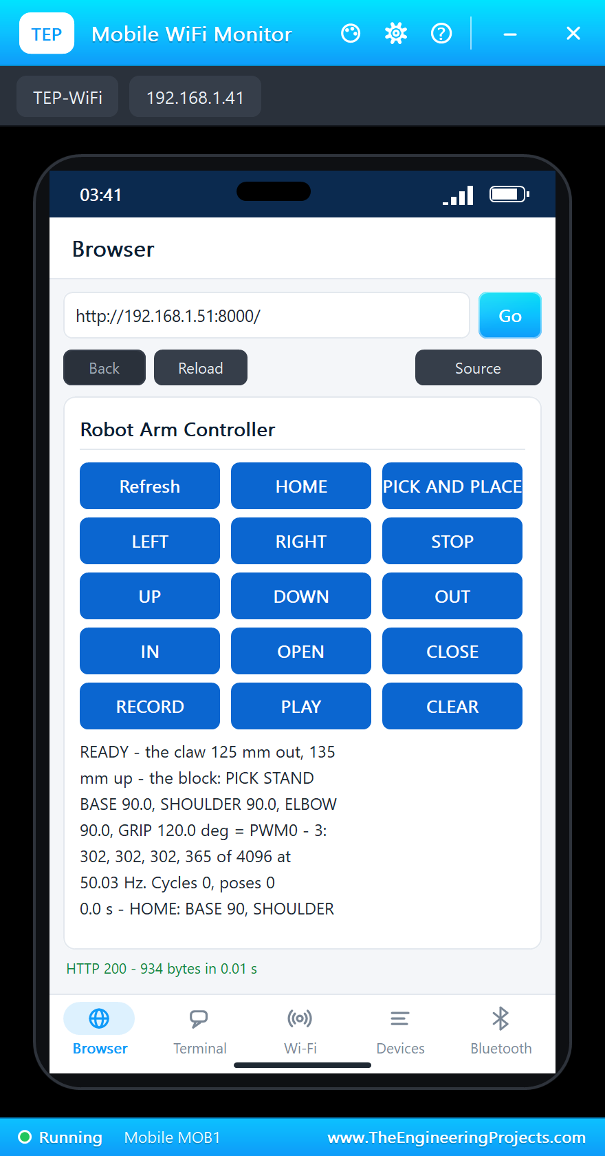
return '%s refused: (%.0f, %.0f) mm is out of reach' % (what.upper(), out, up)The pages are / (the dashboard), /home, /pick (PICK AND PLACE), /stop, /left and /right (the base 15 degrees), /up, /down, /out and /in (the claw 10 mm), /open, /close, /record, /play, /clear and /data (JSON). The dashboard is kept short, because the WiFi Monitors show one screen of a page.
How to Run the Proteus Simulation
- Download the project zip below and install the library files and the TEPPi folder (the steps are under the download button).
- Open Pi-5-Robot-Arm.pdsprj from the Proteus Simulation folder. Keep robot_arm.py and the DLL files next to it.
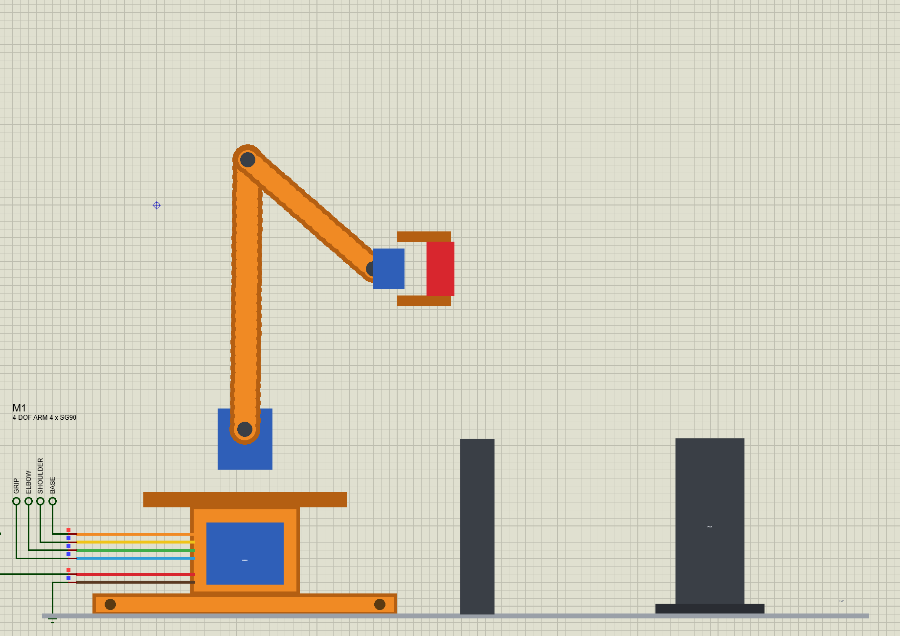
- Press Play. The arm goes to its home pose, the claw 125 mm out and 135 mm up.
- Open the Laptop WiFi Monitor (PC1) or the Mobile WiFi Monitor (MOB1) and press Go.
- Press PICK AND PLACE and watch the arm on the sheet and in its pop-up (click the arm).
- Try the jogs, RECORD a few poses and PLAY them, and STOP the arm in the middle of a move.
Proteus Simulation Results
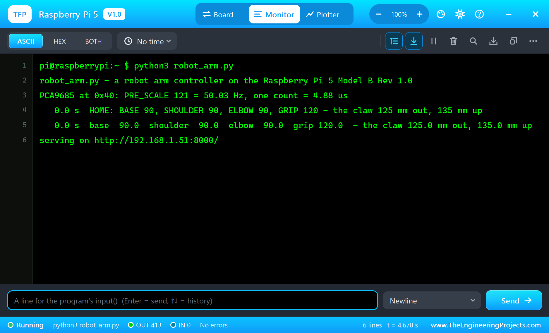
Here is one complete run of the simulation, with the numbers from our final test run; the times are the program's seconds since it started. The Pi's terminal printed "PCA9685 at 0x40: PRE_SCALE 121 = 50.03 Hz, one count = 4.88 us" and the home pose: BASE 90, SHOULDER 90, ELBOW 90, GRIP 120, the claw 125 mm out and 135 mm up, exactly the forward kinematics worked out above.
The PCA9685's pop-up showed RUNNING at 50.0 Hz with four servo pulses: 1,474 microseconds on channels 0 to 2 (302 counts, 90 degrees) and 1,781 microseconds on channel 3 (365 counts, the claw open at 120 degrees). It also confirmed the start-up: PRE_SCALE 121 from the 25 MHz oscillator, MODE1 awake with auto-increment, MODE2 totem pole, VCC 3.30 V, V+ 5.00 V and OE low. The arm's pop-up showed it holding its home pose, the block on the pick stand, 0.02 A for the four servos.
Pick and Place
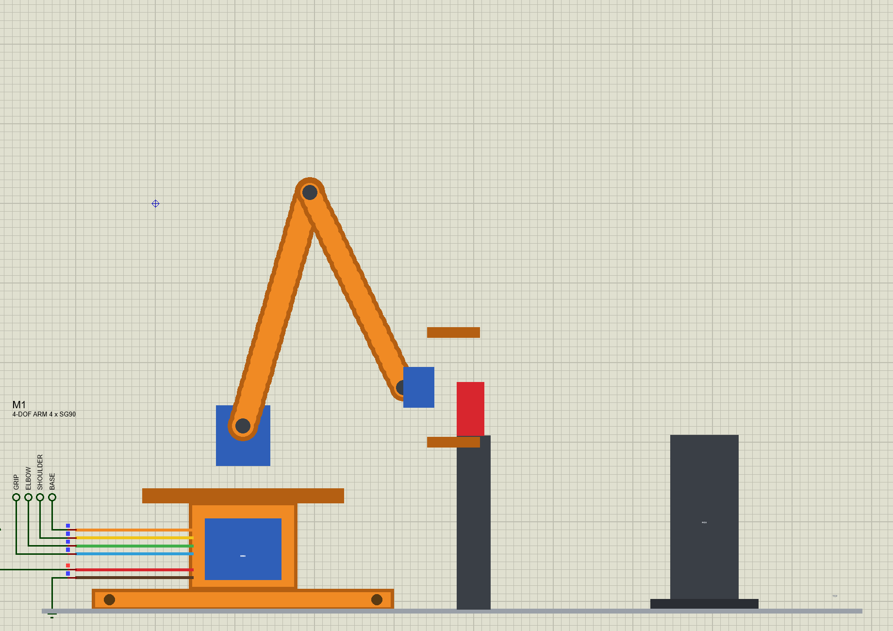
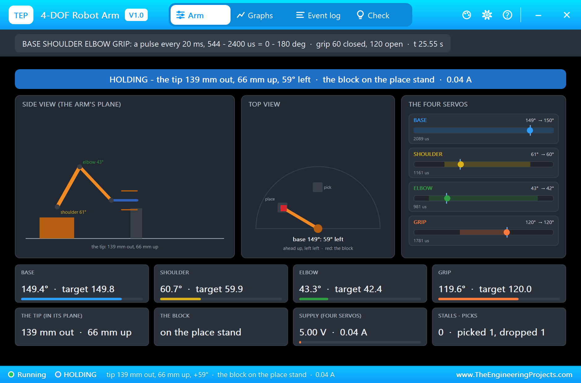
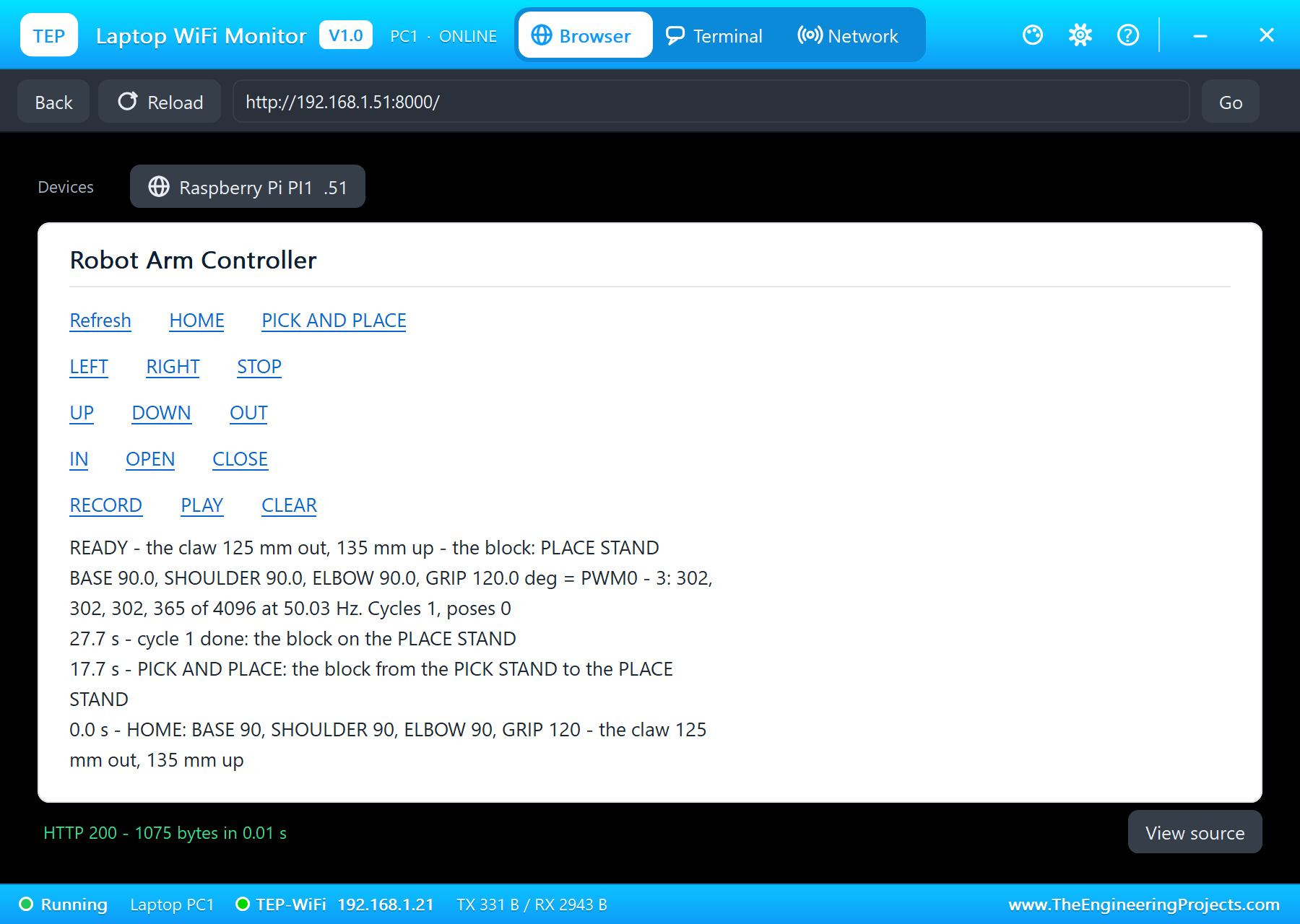
PICK AND PLACE on the laptop at 17.7 seconds: "the block from the PICK STAND to the PLACE STAND". The program printed each point as the arm reached it: above the block at 18.5 seconds, down to the block at 19.4 seconds (SHOULDER 58.7 and ELBOW 41.0 degrees, the inverse kinematics of 139 mm out and 63 mm up), the claw closed at 20.5 seconds. The arm's pop-up then said HOLDING, the block in the gripper: the jaws had stopped at 92 degrees on the 16 mm block while the program asked 85, so the claw servo pressed on the block and the four servos drew 0.56 A instead of 0.04 A. The real angles also lagged the asked ones by about a degree under the load, as real servos do.
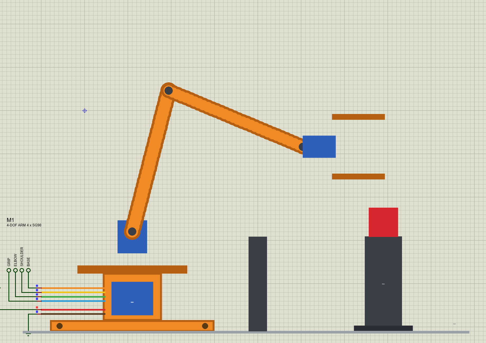
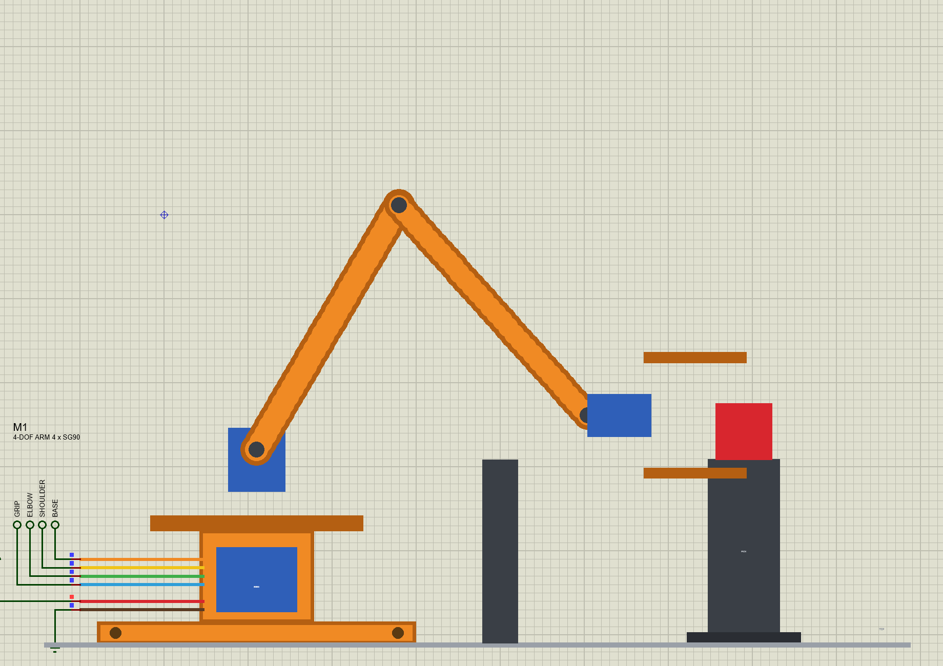
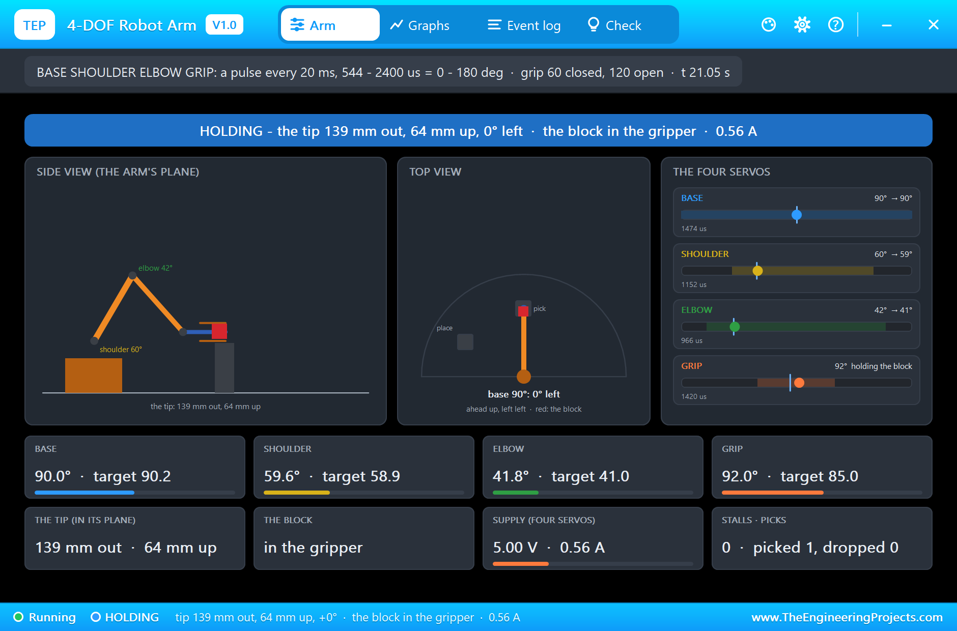
Lift at 21.4 seconds (120 mm out, 105 mm up), the base turned to the place stand, 60 degrees to the left, by 22.9 seconds, lowered at 23.8, let go at 24.9, up at 25.8 and home at 27.3 seconds: "cycle 1 done: the block on the PLACE STAND" at 27.7 seconds. A whole cycle took 10 seconds. On the sheet, the arm moved through every step at true scale; when the base turns, the side view shows the arm's plane at an angle, so the arm looks shorter.
Jogging Until It Is Out of Reach
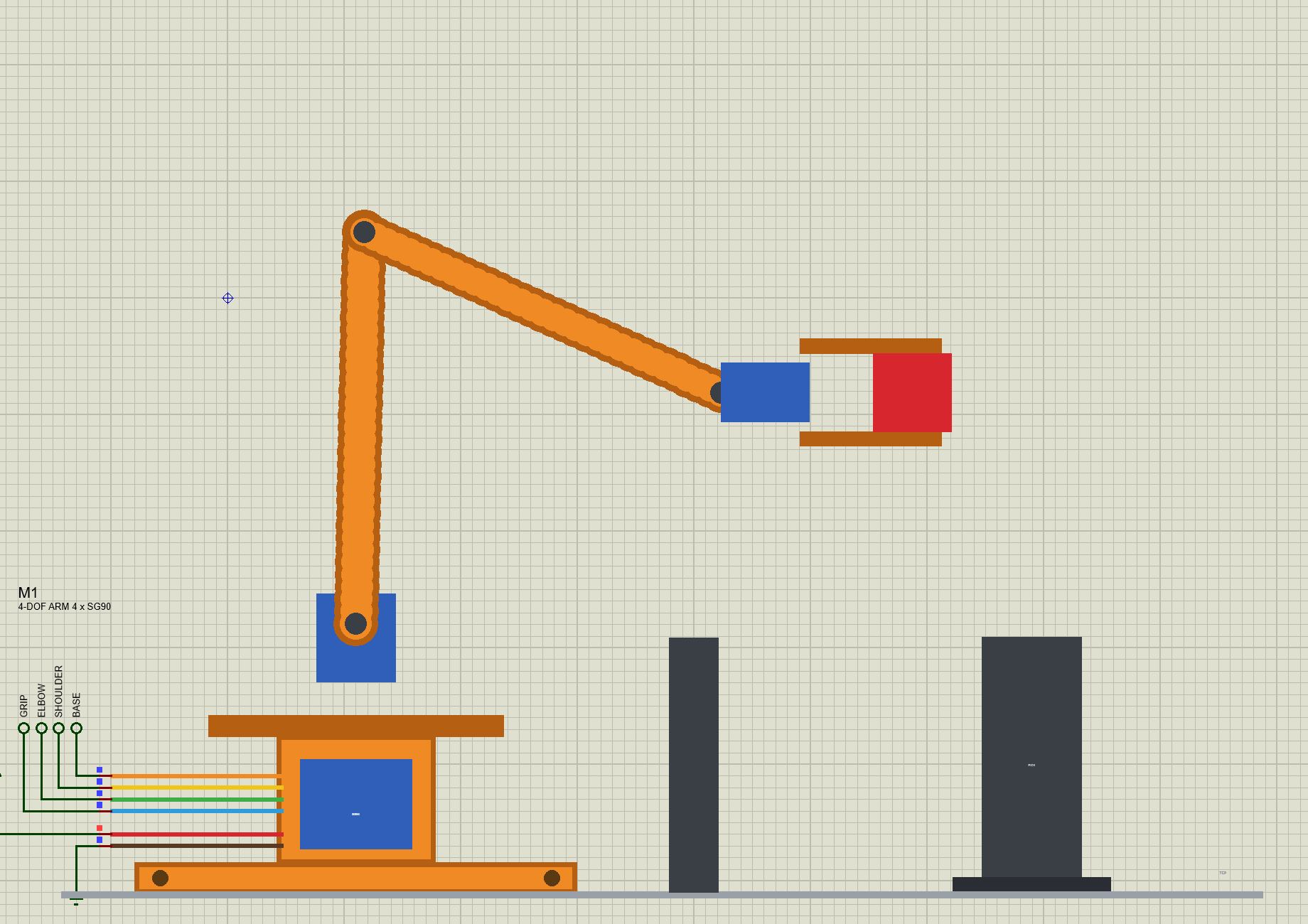
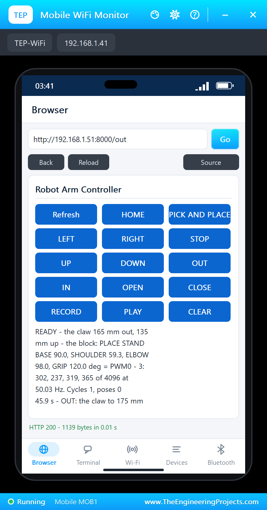
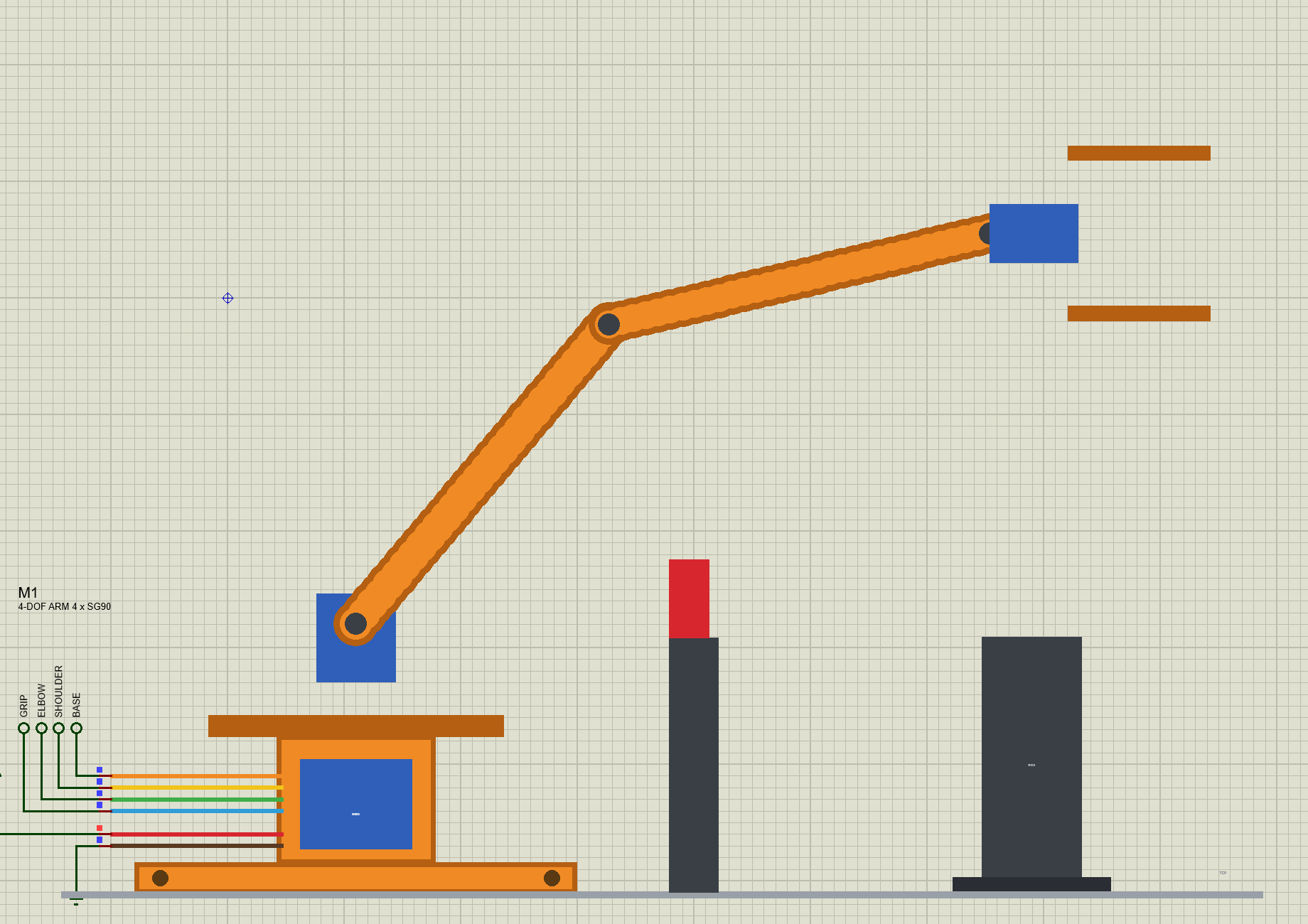
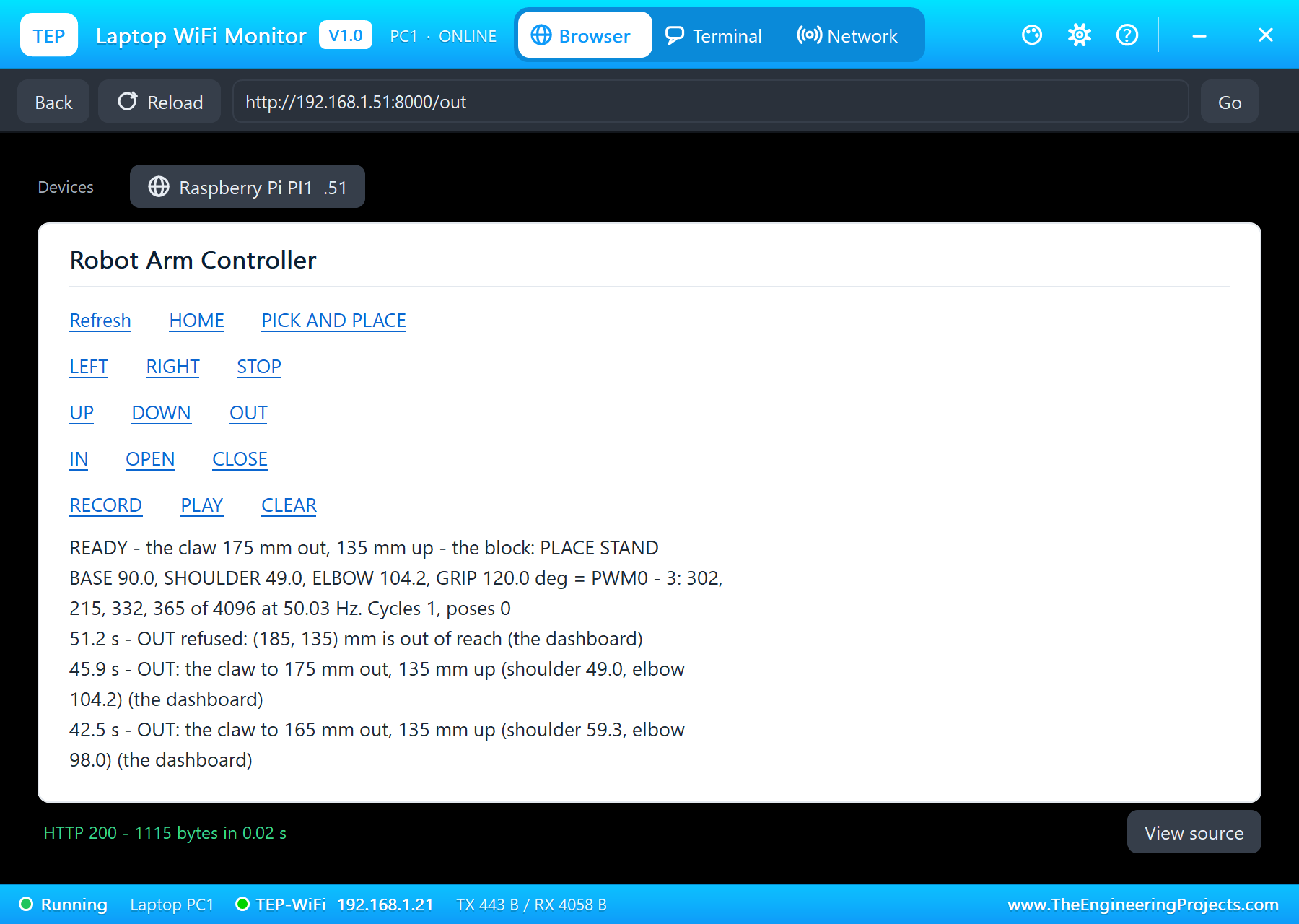
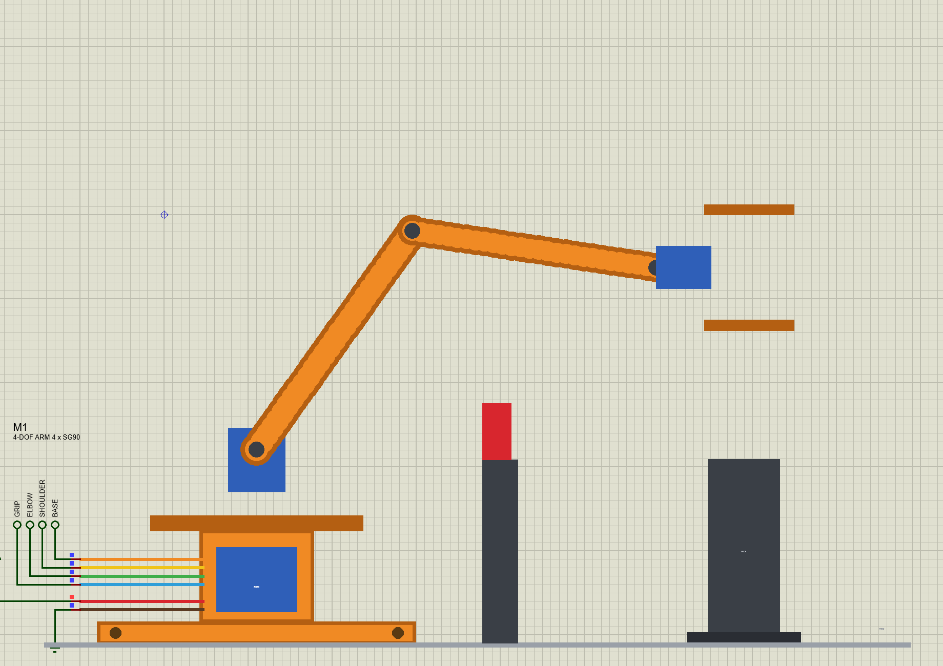
Five presses of OUT on the phone moved the claw 10 mm at a time, the inverse kinematics working out every step: 135 mm (SHOULDER 82.8, ELBOW 90.4), 145 mm (75.5, 91.8), 155 mm (67.8, 94.2), 165 mm (59.3, 98.0) and 175 mm (49.0, 104.2), the claw always 135 mm up. A sixth press asked for 185 mm: the wrist would be 161.2 mm from the shoulder, more than the two 80 mm arms can reach, and the program answered "OUT refused: (185, 135) mm is out of reach" without moving anything.
Teach and Repeat
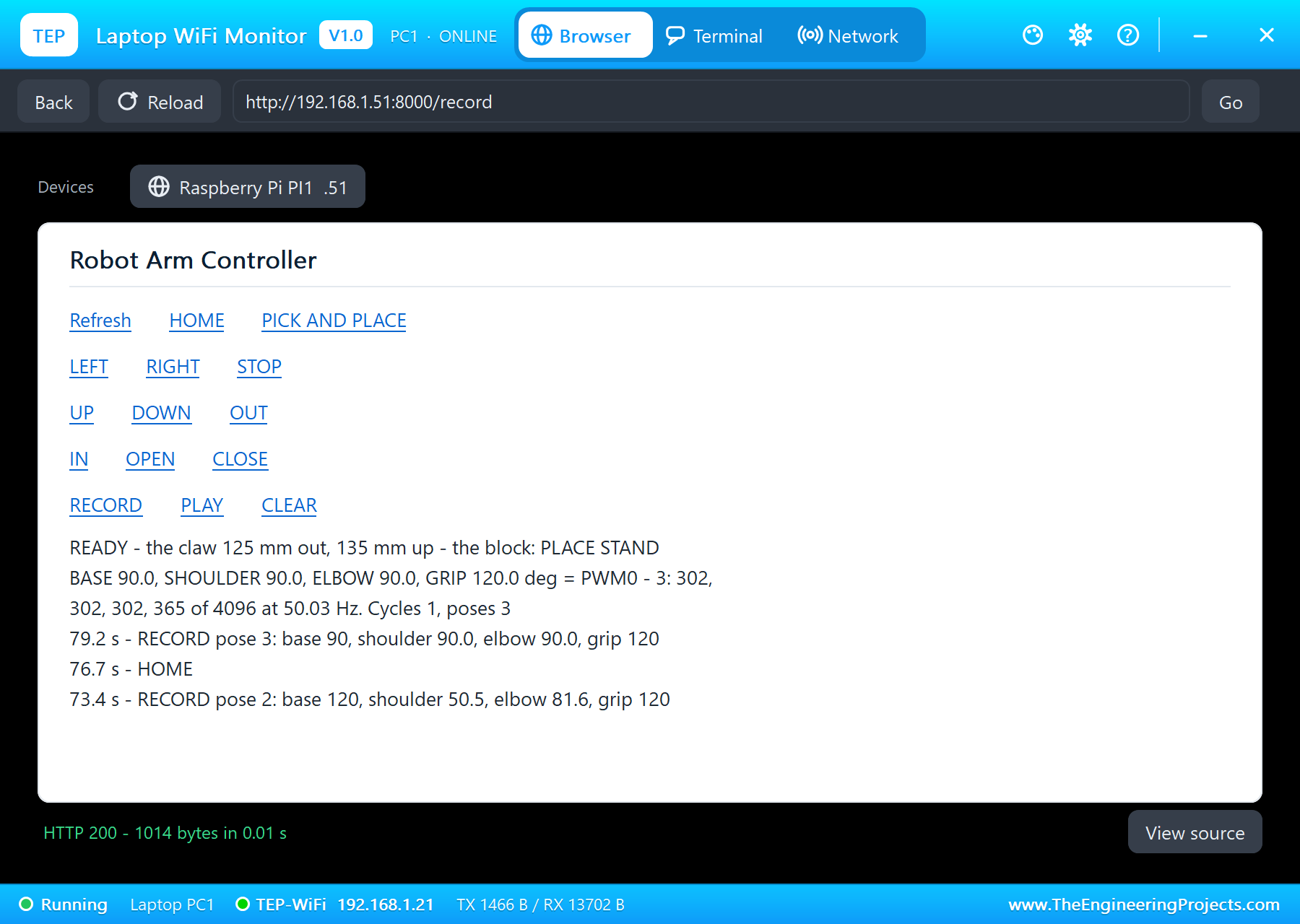
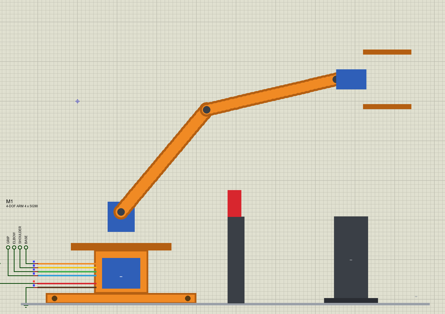
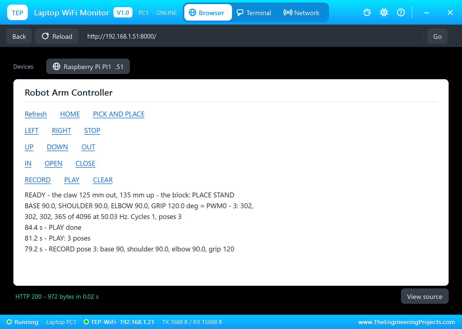
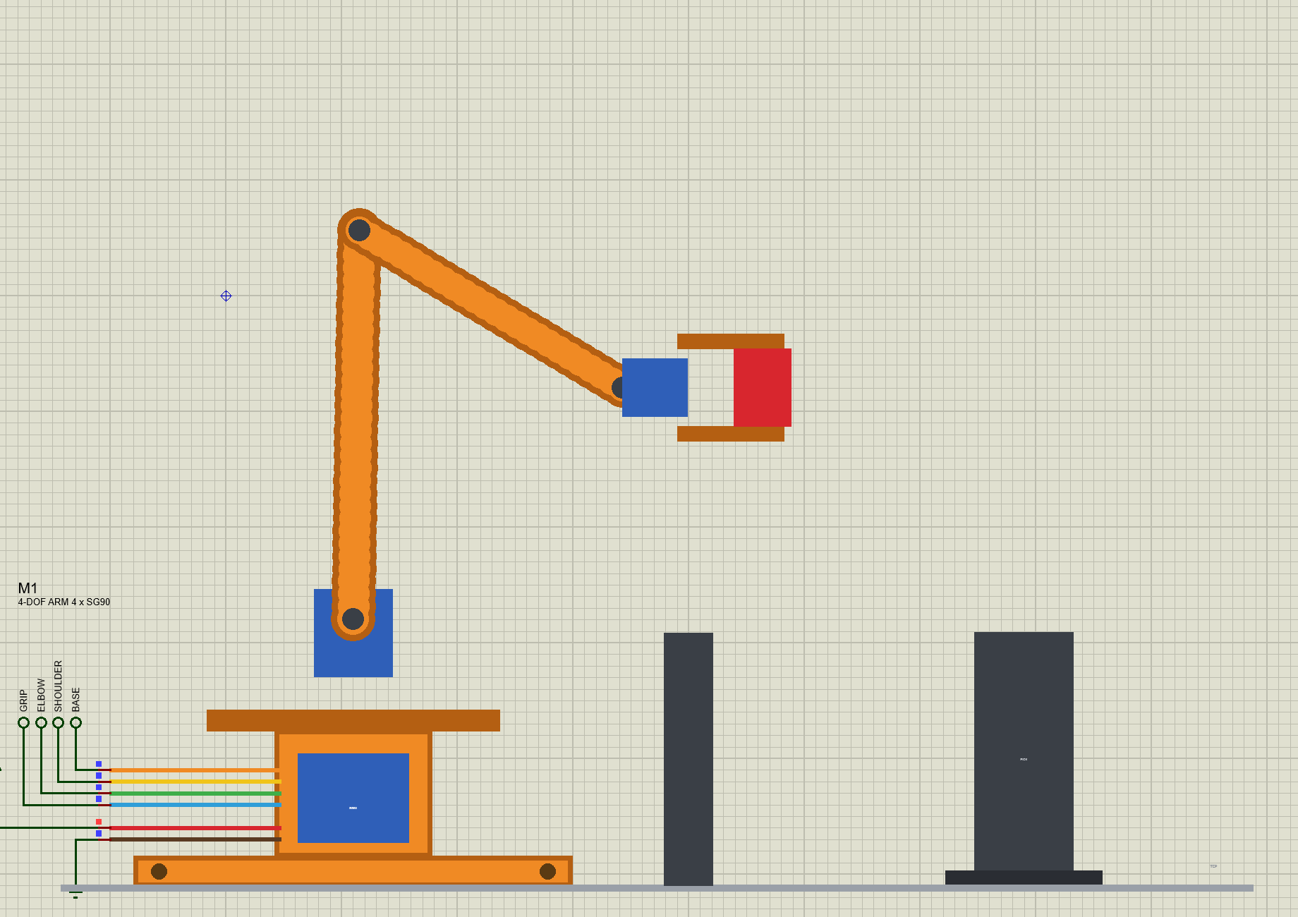
RECORD stored the stretched pose as pose 1. LEFT twice turned the base to 105 and 120 degrees, and DOWN three times lowered the claw to 105 mm (SHOULDER 50.5, ELBOW 81.6): RECORD, pose 2. HOME, RECORD: pose 3. PLAY at 81.2 seconds moved the arm through the three poses in 3.2 seconds, and "PLAY done".
STOP with the Block in the Claw
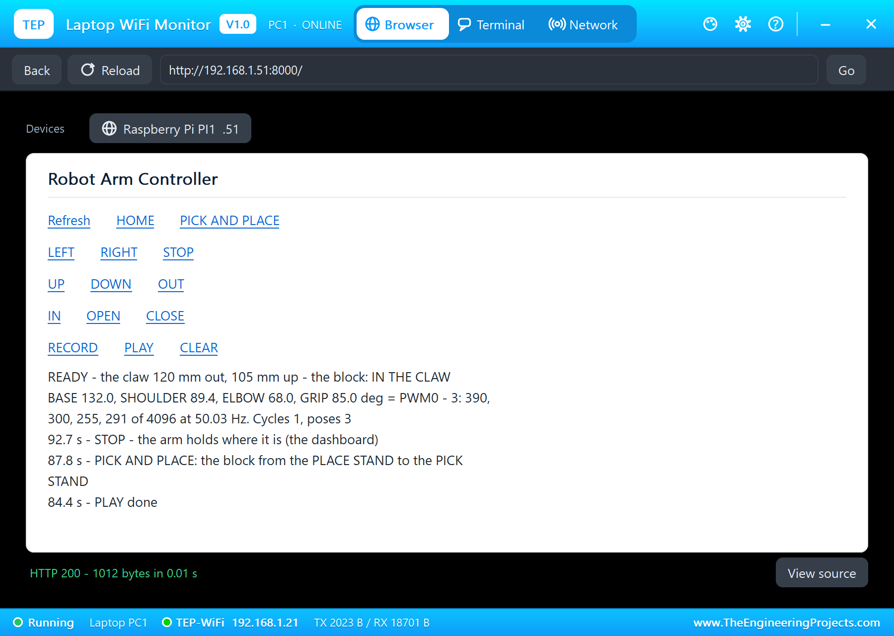
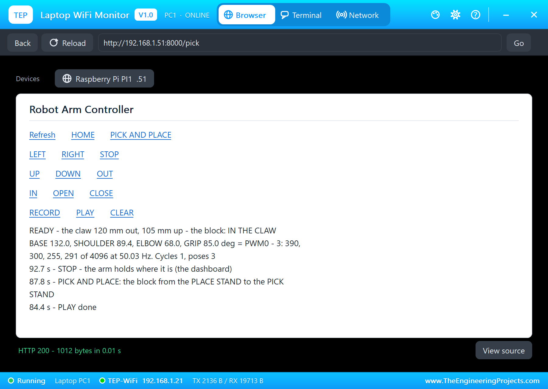
PICK AND PLACE again at 87.8 seconds carried the block back from the place stand. As the base turned with the block in the claw, STOP on the laptop at 92.7 seconds froze every joint where it was: "STOP - the arm holds where it is". The servos kept their pulses, so the arm held the block in the air. The next PICK AND PLACE at 100.7 seconds knew the block was in the claw: "on to the PICK STAND", and finished the move: "cycle 2 done: the block on the PICK STAND" at 106.0 seconds.
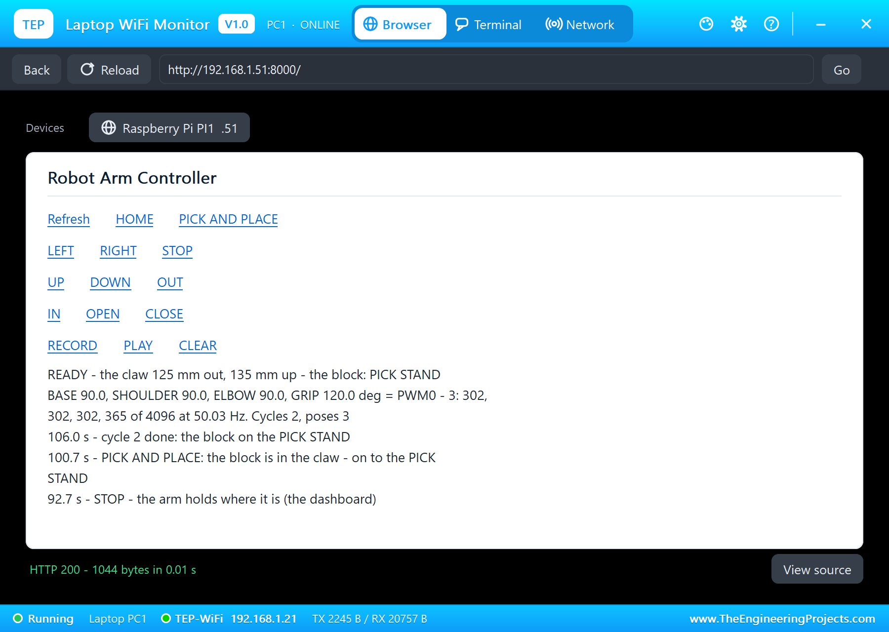
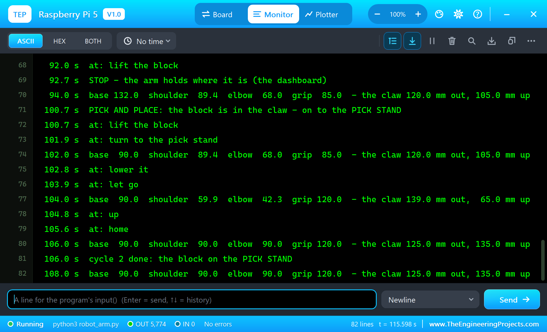
116 seconds of simulation took about 7.5 minutes on our PC with all the captures.
Download the Project Files
Click the button below to download IoT-Robot-Arm-Controller-Raspberry-Pi-5-Proteus-Simulation-v1.0.zip (about 13.4 MB, without the source code of the models):
IoT Robot Arm Controller with Raspberry Pi 5 - Proteus Simulation V1.0- Proteus Simulation: Pi-5-Robot-Arm.pdsprj, the program robot_arm.py and copies of the models.
- Python Code: robot_arm.py, the complete program.
- Proteus Library Files: the LIB files of the Raspberry Pi 5, the PCA9685, the robot arm and the two WiFi Monitors.
- Proteus Model Files: the DLL models and the TEPPi folder, the Python 3.11 and the runtime that the Pi board runs.
- README.txt: the installation steps, the properties, the test results and the links to every library post.
No Proteus yet? Read How to Download and Install Proteus 7 and 8. New to libraries? Follow How to Install a New Library in Proteus.
How to Install the Project Files
- Close Proteus and extract the whole zip file, for example to your Desktop.
- Copy the files from Proteus Library Files into the LIBRARY folder of Proteus.
- Copy everything in Proteus Model Files, the DLL files and the TEPPi folder, into the MODELS folder.
- Start Proteus and open the project from the Proteus Simulation folder.
Changing the Code
The program is plain Python 3: edit robot_arm.py beside the project and press Play again; the Pi board runs the new file. The arm's lengths, the joints' limits, the speed and the stands' positions are at the top. The same program runs on a real Raspberry Pi 5 with Raspberry Pi OS and lgpio; enable I2C in raspi-config. For a servo driven straight from a Pi pin with lgpio's tx_servo(), see the Raspberry Pi 5 Smart Parking System.
Ideas to Extend the Project
- Add a joystick or two slide potentiometers on an ADC and drive the claw by hand.
- Give the dashboard a target in millimetres: type out and up, and let the inverse kinematics do the rest.
- Add a camera and pick the block wherever it lies.
- Save the recorded poses to a file, so a taught job survives a restart.
- Ease the moves: speed up and slow down along an S-curve instead of a constant speed.
- Use the PCA9685's other 12 channels for a second arm or a conveyor servo.
From Simulation to Real Hardware
- Power the servos separately: four SG90s can draw well over 1 A when they start or stall; give V+ its own 5 V supply of 2 A or more, and join its ground with the Pi's.
- Add a capacitor: 470 to 1,000 microfarads across V+ smooths the current peaks.
- Calibrate each servo: real SG90s differ; find the pulse widths that give 0 and 180 degrees for each one.
- Calibrate the frequency: the PCA9685's oscillator is 23 to 27 MHz on real chips; measure the period and adjust the oscillator value in the code.
- Respect the stops: a servo pushed against a mechanical stop draws its stall current and heats up; keep the limits inside the arm's real range.
- Keep VCC at 3.3 V: the board's I2C pull-ups go to VCC, and the Pi's pins are not 5 V tolerant.
Troubleshooting
- No servo moves: OE is high (all outputs off), or V+ has no supply.
- The program stops at the start with an I2C error: SDA and SCL swapped, or the address jumpers are not 0x40.
- The servos buzz and the angles are wrong: the frequency is not 50 Hz; PRE_SCALE was written while the chip was awake.
- The claw misses the block: the arm's lengths in the code do not match the arm; measure them again.
- A jog does nothing: the point is out of reach; the dashboard's events say so.
- The terminal cannot start Python: the TEPPi folder is not in MODELS.
Limitations of the Simulation
- The arm in the simulation is drawn from the side at true scale; its pop-up adds the top view. The block is a fixed 16 mm cube on two fixed stands.
- The program moves the arm open-loop: it knows where it sent the joints, not where they are; the arm's pop-up shows the real angles and the lag under load.
- The network is simulated: the dashboard travels between the Pi and the two monitors inside Proteus; the times in this tutorial are simulation time.
- Raspberry Pi is a trademark of Raspberry Pi Ltd and the PCA9685 a product of NXP Semiconductors; the arm is a generic kit. This project is not made or endorsed by them or by Labcenter.
So, that was all about the IoT Robot Arm Controller with Raspberry Pi 5 - Proteus Simulation. I hope it helps you build your own robot arm: a PCA9685 making the servo pulses in hardware, forward and inverse kinematics in a few lines of Python, smooth moves, a pick-and-place sequence and a taught job, all tested in a simulation before you power a single servo. More IoT projects with the ESP32 and the Raspberry Pi 5 are coming in this series. If you have any questions, ask in the comments and I will help you out. Till the next tutorial, take care and have fun!