This is the next lesson in our Python course. Previously, we looked at an overview of the different data types in python such as dictionaries, Boolean and sets. This tutorial will focus on Python sets to get a deeper understanding of this data type, so let's get started. During your schooling, there is a good chance you learned about sets and set theory. Venn diagrams may even be familiar to you:
Don't worry if you don't recognize this! You should still be able to access this tutorial without any problems. Rigidly defining a set in mathematics can be both abstract and difficult to understand. A set is thought of as a well-defined group of unique objects, which are sometimes called "elements."
Python's built-in set type facilitates the grouping of ...
Hi Friends! Glad to have you on board. Thank you for clicking this read. In this post today, I’ll walk you through Edge Computing vs Cloud Computing.
Cloud computing has been around for many years while edge computing, on the other hand, has just become the prime topic of mainstream organizations. But what is the key difference between both edge computing and cloud computing, how do they work, can we implement both in the IT model of any business? These are the main questions that arise every time someone tries to get a hold of these terms. Don’t worry. We’ll discuss them in detail so you know when to pick a cloud model and when to choose edge computing.
Keep reading.
Edge Computing vs Cloud Computing
Before we go further to describe the comparison between edge and cloud, know that, both ...
Welcome to the next tutorial of our python course. We learned about python numbers in the last tutorial, and in this tutorial, Data types in Python include, dictionaries, sets, and Boolean, among others. We'll give a quick overview of the above data types in this section but later in this course, we'll go over each of them in-depth.
Introduction
In the Python programming language, data types are a necessary concept. Python assigns a data type to each value. Data Types are used to classify data objects or to assign a value to a data category. It aids in comprehending the many operations that can be applied to a value.
Python considers everything to be an object. Classes are represented by data types in Python. Variables are the names given to the ...
Hello readers, I hope you all are doing great.
ESP32 is a powerful chip for Internet of Things applications. This tutorial is also based on one of the ESP32 applications in the field of IoT.
Project Overview
In this tutorial, we will learn how to update LCD display with new data or input using a web server created with ESP32.
Fig. 1
To achieve the target, we will be using an HTML (Hypertext Markup Language) form to provide web input and then update the text displayed on LCD. The values or input received from the webserver will be further stored inside a variable in the code for further use (to display on LCD).
We have already posted a tutorial on LCD (Liquid Crystal Display) interfacing with ESP32. In that tutorial, we demonstrated how to displa ...
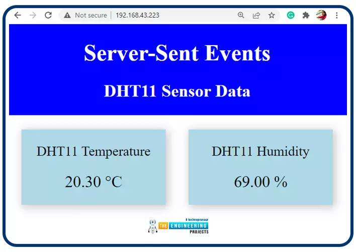
Hello readers, I hope you all are doing great. In this tutorial, we will learn how to update a webpage using Server-Sent Events and the ESP32 web server.
What is Server-Sent Events (SSE)?
It is a server push technology that enables the client devices to receive automatic updates from a server over HTTP (Hypertext Transfer Protocol) connection. SSE also describes how the server can initiate data transmission towards the client once an initial connection with the client has been established.
We have already posted a tutorial on how to implement Web socket protocol with ESP32 which is also a protocol used to notify events to a web client. Both the Server-Sent Events (SSE) and Web-Socket technologies seem to be quite similar but they are not.
The major difference between the two is that SSE ...
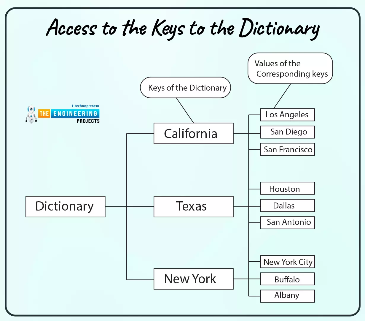
Hello! Welcome to the next lesson in this Python course. In the last session, we learned about python tracebacks and how to deal with them. A dictionary, like a list, is a collection of items, and we'll look at that in this tutorial as well.
What will you learn?
This tutorial introduces you to the fundamentals of dictionaries in Python and teaches you how to work with dictionary data. After reading this article, you should be able to tell when and how to utilize a dictionary as a data type.
Characteristics of Dictionaries and lists
Both can be changed (mutability).
A dynamic relationship exists between them. When needed, they're able to expand and contract.
Both are nestable. Another list can be ...
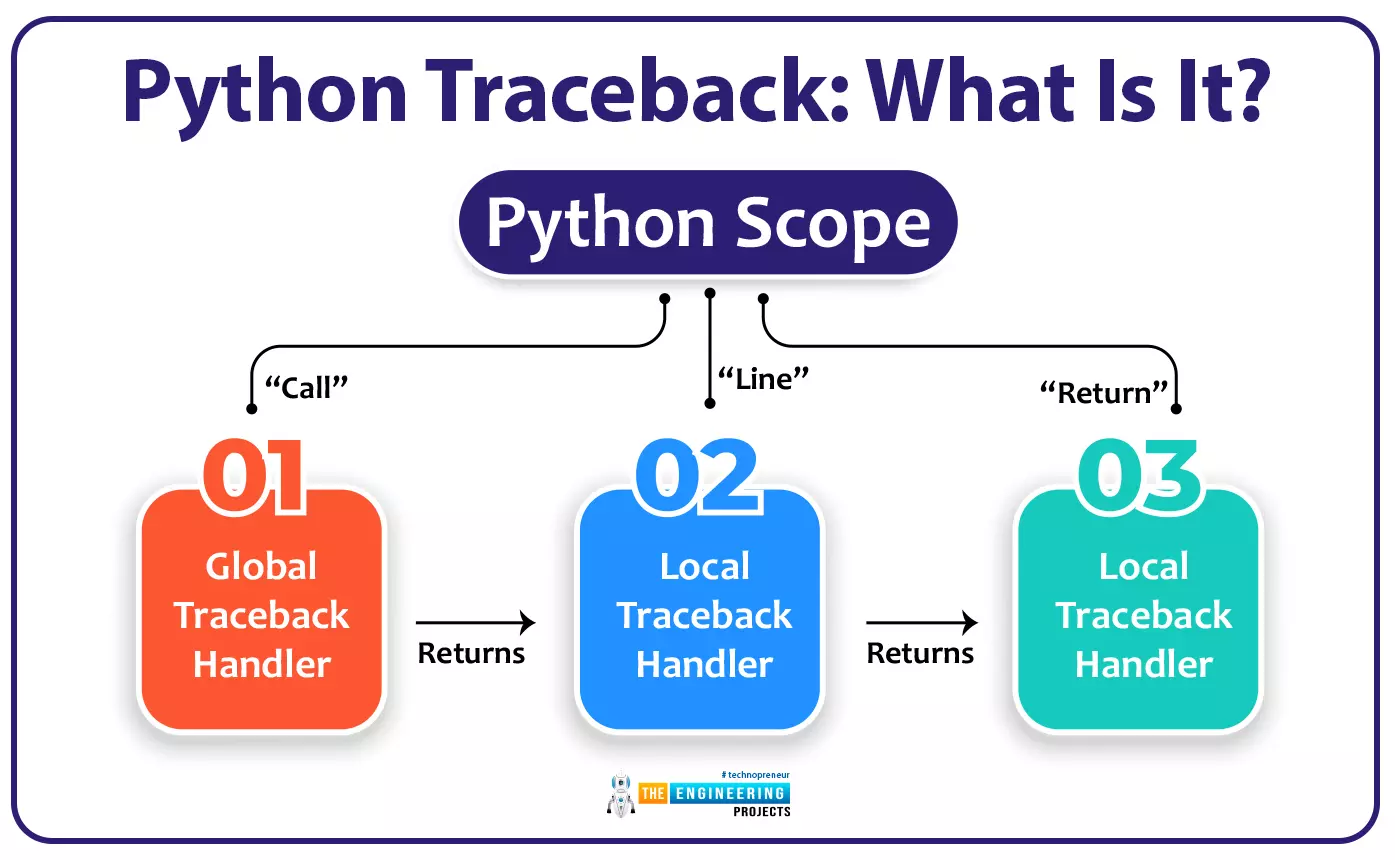
Welcome to the tenth lesson of our python course. In the previous tutorial, you learned about syntax errors in Python, and in this lesson, we will look at one more error notice that is given by Python when there is an error in your code. So, without further ado, let's get started.
Any time an exception is thrown in your code, Python shows you the stack trace. If you don't know what the traceback output is showing you, it can be a little overwhelming. Python's traceback, on the other hand, provides a goldmine of information that can assist you in figuring out why an exception was triggered in your code and fix it. It's essential to learn how to use Python traceback to become a better coder.
After completi ...
Welcome to chapter 9 of our python tutorial. In the previous chapter, we looked at frequent examples of invalid Python syntax and learned how to fix them. Up to this point, you are well aware of errors that may occur in your Python program and how you can solve them easily and quickly. Therefore, in this tutorial, we will look at a few more causes of syntax errors and zero-error divisions.
Mistaking Dictionary Syntax
As you learned before, omitting the comma from a dictionary element can result in a syntax error. In Python dictionaries, the equals symbol (=) is used instead of a colon to separate key and value pairs.
This error message is once again useless. In this case, the repeated line and caret come ...
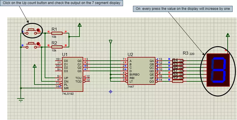
Hello geeks, welcome to our new project. In this project, we are going to make a very interesting project. I think most of us have seen the scoreboards in sports, after looking at that, have you ever wondered about the working of it. Therefore, this time, we will be making something like that only with some extra features. So basically that score board is nothing but a counter which counts the scores. Most of the geeks who have an electronics background or have ever studied digital electronics must have heard about the counter.
Here, in this project, we are going to make an Up-Down counter. A simple counter counts in increasing or decreasing order but the Up-Down counter counts in increasing and decreasing order, both depending upon the input it h ...
Hey readers! I hope you are doing good and learning something. Have you ever thought about electric vehicles, which are rechargeable and run on a battery? Now, it is possible, and today, we will discuss electric vehicles.
All over the globe, EVs have made a major difference by being a cleaner and cheaper way to travel than gasoline and diesel cars. Unlike cars with engines, electric cars are environmentally friendly because their engines use rechargeable batteries and give out no emissions. The rise in buyers and producers of EVs is thanks in part to new kinds of batteries, better motors, and certain actions taken by the government.
Because of their various operating systems, Battery Electric Vehicles (BEVs), Plug-in Hybrid Electric Vehicles (PHEVs), Hybrid Electric Vehicles (HEVs), and ...