Hello everyone! I hope you all will be absolutely fine and having fun. Today, I would like to provide a complete discussion on introduction to GPS and myRIO as well as myRIO GPS Interfacing as the most related part. First of all I would like to tell you about GPS, from what it is abbreviated, at which principle it works and how it plays its role in our daily life. GPS is basically derived from the word Global Positioning System. GPS is a complete network of satellites which are continuously rotating in their orbits and send information to earth about their accurate position in space. GPS receivers are used to receive the signals, and the received signals help us to estimate the precise time, position and speed of anything moving around. I have sh ...
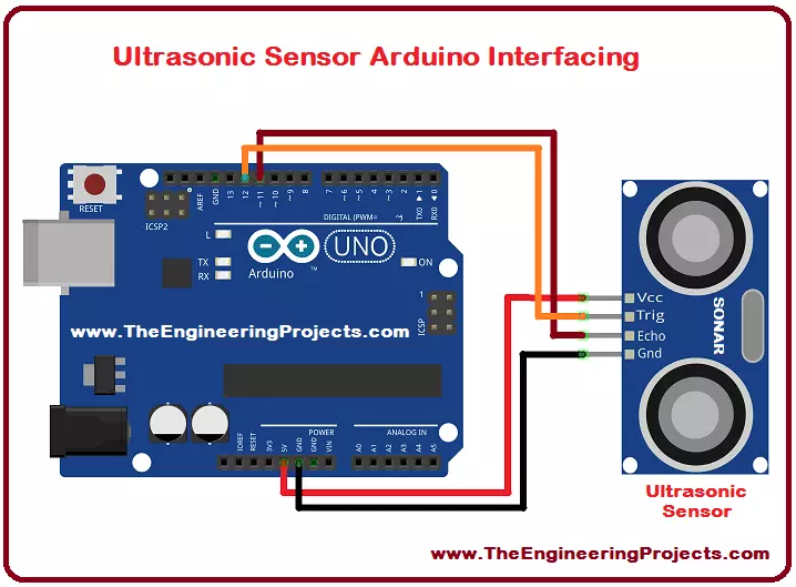
Hello everyone! I hope you all will be absolutely fine and having fun. Today, I would like to provide a complete discussion on Ultrasonic Sensor Arduino Interfacing. I would like to tell you some detail about ultrasonic sensor, after that we will move towards ultrasonic sensor Arduino interfacing. Ultrasonic sensor is also known as SONAR sensor. SONAR basically stands for Sound Navigation and Ranging. Ultrasonic is mostly used for the distance measurements. It can also be used for measuring the depth of the sea.
I have already shared Ultrasonic Sensor Library for Proteus. Ultrasonic/SONAR sensor is an electronic device used to estimate the distance of an object by continuously transmitting sound waves at a particular frequency and listens to tha ...