Assessing Cybersecurity Challenges in Virtual Office Environments

In today's digital age, remote workers are on the frontlines of an invisible war, battling unseen cyber threats. As they maneuver through the complex terrain of remote work environments, they're confronted with potential hazards at every turn.

From a compromised network and data breach to phishing attacks, remote workers are tasked with safeguarding the organization's digital fort.

Building a cybersecurity culture

The remote workforce is instrumental in building a cybersecurity culture where everyone becomes their own expert, advocating for security measures and promptly reporting suspicious activities. This culture is particularly significant in virtual office environments, where workers are the custodians of sensitive data.

As remote employees constantly face cybersecurity challenges, from unsecured Wi-Fi networks to malware attacks, their actions shape the security landscape of their organization.

This environment isn't built overnight but through continuous education and reinforcement of secured virtual office tools from trusted providers like iPostal1 .

Ensuring secure network access

While remote workers are integral to building a cybersecurity culture, it's equally essential to have secure network access, especially when working virtually. Remote work security risks are abundant. Hence, implementing cybersecurity solutions for remote working is critical.

Secure network access can be achieved through virtual private networks (VPNs), providing a safe conduit for data transmission.

However, a virtual private network alone isn't enough. Multi-factor authentication (MFA) adds an extra layer of security, reducing the possibility of unauthorized system access. With MFA, even if a cybercriminal cracks your password, they're still one step away from breaching your account.

Password protection and router security

Even though you've secured your network access, don't overlook the importance of password protection and router security in maintaining robust online network security.

Remote workers must change default passwords on home routers and ensure the creation of strong, unique ones. Regular reminders to change these passwords can also help strengthen the router's security.

Moreover, using a mix of characters, numbers, and symbols and avoiding easily guessable phrases can fortify password protection. Remember, the stronger the password, the more challenging it is for cybercriminals to breach it.

Staying ahead in the cybersecurity game requires continuously reviewing and enhancing these protection measures.

Instituting remote work cybersecurity policies

Building on the importance of password protection and router security, remote working involves instituting cybersecurity policies and best practices to further safeguard the virtual office environment.

While remote workers assess the cybersecurity challenges in virtual office environments, they must learn the vital role these policies play in protecting sensitive company data.

Cybersecurity policies cover all aspects of data handling, from remote access procedures to transfer and storage. It includes guidelines on secure network use, encryption protocols, and device security.

Businesses must ensure their policies are comprehensive to address all areas where sensitive company information might be at risk. Regularly reviewing and updating these policies will help organizations avoid emerging threats.

Anti-malware software and phishing Prevention

To ramp up the company's cybersecurity defenses, remote work leaders should prioritize installing robust anti-malware software and educating their team on how to avoid phishing scams.

Anti-malware software is the first line of defense against cybersecurity threats, capable of detecting and neutralizing malicious programs before they infiltrate the system.

But software alone isn't enough. Phishing prevention is equally important, as phishing attacks are increasingly sophisticated, often involving social engineering attacks. These scams trick remote workers into revealing sensitive information, compromising security.

The combination of both robust software and thorough education is vital to a secure virtual office environment.

Strengthening authentication methods

As remote workers fortify their virtual office's cybersecurity, focusing on security infrastructure and strengthening authentication methods is critical.

Robust authentication methods help to ensure that only authorized individuals have access to sensitive data. Remote work leaders must consider biometrics as an additional layer of security for personal devices.

Whether fingerprint scanning, facial recognition, or voice patterns, these technologies can add a more secure, personal touch to remote work authentication methods.

Implementing a zero-trust strategy

To enhance cybersecurity, remote work leaders must implement a zero-trust strategy for cloud security. A zero-trust approach assumes no user or device is trustworthy, be it inside or outside the network.

This strategy demands verification for every access request, thus reducing the cybersecurity risks of data breaches.

As virtual office environments become more prevalent, the cybersecurity risks and challenges they present require advanced strategies.

Before implementing a zero-trust strategy, assessing your data's sensitivity and storage locations is critical. Remember, zero trust should only be applied where it aligns with your organization's needs and capabilities.

This approach is particularly beneficial for protecting data stored in the cloud . By assessing cybersecurity challenges and adopting a zero-trust strategy, you bolster your defenses against potential threats.

New technologies and employee education

Just like implementing a zero-trust strategy, adapting to new technologies is crucial to fortifying your virtual office's cybersecurity. However, ensuring your employees are well-versed in these changes is equally vital.

Before introducing new systems or software, verifying compatibility with the existing tech stack is crucial. This step will help avoid potential conflicts or vulnerabilities arising from integrating new technology.

The next step is educating remote work staff. This part goes beyond simply training employees on how to use new software. It's about making them understand why these changes are necessary for security.

Educating remote work employees on the importance of cybersecurity can encourage a culture of vigilance and active participation in your defense strategy.

Regular training sessions, updates on emerging threats, and clear communication lines for reporting suspicions are essential. These measures will empower your workforce to contribute effectively to your cybersecurity efforts.

By keeping them informed and providing them with the remote working tools they need, employees can be an asset in protecting virtual office data from potential threats.

Final words

Balancing cost and robust security measures is no small feat. Yet, with diligent attention to network access, secure passwords, and comprehensive policies, remote workers can successfully navigate these murky waters. Embrace a zero-trust strategy and wield new technologies to be steadfast guardians. Remember, every vigilant eye is a lighthouse against potential threats in cybersecurity.

3 Options for Creating Custom CNC Machined Parts for Your Next Engineering Project

By using CNC-machined parts for your next engineering project, you can ensure precision, quality, and speed. So, let us take a look at three options for creating custom parts. 

What Is CNC Machining? 

Before we look at the three options available to you, it is worth briefly explaining what CNC machining is. CNC machining is short for Computer Numerical Control. It is a modern manufacturing method that involves the use of computer-controlled machinery to make custom parts.

The process begins with creating a CAD design of the part you want to make. The design is then translated into g-code and fed into the item of CNC machinery.

The machine then simply gets to work at creating your design with the utmost precision and consistency. The types of CNC machines range widely – from milling machines and lathes to routers and grinders. Each type has its unique advantages depending on your specific production needs.

CNC machining comes with numerous benefits. These include improved efficiency, enhanced safety, consistent quality, and significant time savings.

Additionally, this manufacturing method allows for a wide range of materials to be used. Metals like steel and aluminum are common. But plastics like nylon or ABS as well as wood can be processed.

Now, here are your three options for creating the custom CNC machined parts you need for your next engineering project

1. Purchase New CNC Machinery 

Firstly, you have the option to purchase new CNC machinery. If the scale of your project is substantial or if you foresee continuous use, investing in new machinery could well be the best economical choice in the long run.

New CNC machines represent the crux of modern manufacturing technology. They usually have more current features and capabilities compared to older models – including newer software, which offers advanced programming and control options that result in more accuracy and speed.

Remember, when it comes to large-scale repetitive tasks or projects demanding high precision and consistency, nothing beats the efficiency of these machines, so it could definitely be worth investing in the purchase of one or more CNC machines.

Furthermore, owning CNC machinery means you have unrestricted access anytime according to your production schedule’s needs.

Additionally, most new models come complete with warranties that offer maintenance services and part replacement plans from manufacturers. However, a critical factor here is the cost consideration, as top-tier CNC machinery can carry hefty price tags up front.

That being said, many businesses find that prices eventually pay off through improvements in production efficiency, product uniformity, and reductions in material waste.

Overall, acquiring new CNC machinery is not just an asset purchase but an investment towards improved operational efficiency and product quality for your upcoming projects. 

2. Purchase Used CNC Machinery 

A cheaper option is to buy used CNC machinery for your engineering project. This alternative can be particularly attractive if you are working with a limited budget or if the project is not continuous or large-scale.

Used CNC machines often come at a much lower price point in comparison to new ones. Depending on factors such as age, condition, and functional capacity, you might discover good deals that cater perfectly to your needs without straining your budget.

While they may lack some of the advanced functions found in the newest models, well-maintained used machines can still provide commendable performance in precision and repetitive tasks.

However, take note that maintenance consideration is key. Since warranties may not be available for older models, setting aside a budget for potential repairs is prudent. 

3. Use an Online CNC Machining Service

Lastly, you may want to consider using an online CNC machining service for manufacturing the custom machined parts you need for your next engineering project. This option can be the most suitable if you do not have the needed expertise in-house or you lack sufficient workspace. You can also avoid the hefty upfront costs of purchasing machinery.

Online CNC services open up a world of opportunities. They allow access to professional and experienced machinists who operate state-of-the-art machines that cater to virtually any custom specifications. This ensures high-quality parts with excellent precision.

Plus, using such services lifts off the time and effort normally needed for maintaining machines and training personnel. All you need is your digital design file. The service provider will take care of turning your design into a physical part or component. 

Types of CNC Machined Parts You Could Make for Your Next Engineering Project 

For your upcoming engineering project, the possibilities of CNC machined parts you could produce are vast. Whether your project demands small individual components or larger assemblies, CNC machining can cater to them all with unyielding precision.

You can easily manufacture custom components that are specifically tailored to your project’s needs. Here are just some of the common types of CNC machined parts used in engineering projects. 

Gears 

One common part that you can create using CNC machining is gears. Various types such as helical, bevel, or worm gears can be accurately machined. Gears are fundamental in various machinery configurations where power transmission is required. 

Flanges 

CNC machines are also perfect for creating flanges, which are flat rims that enhance strength or provide a method for attachment. As standard components in piping systems, flanges serve to connect pipes or aid in maintenance access points. 

Enclosures 

You can fabricate enclosures too – they serve as protective cases for delicate electrical or mechanical devices. Accurate machining ensures that interior elements fit perfectly while external dimensions comply with assembly requirements. 

Machined Plates 

Machined plates are another type of part you could manufacture with CNC machinery. They are used in numerous applications, ranging from mounting brackets to structural support elements. 

Shafts 

CNC machining is quite useful when making shafts from materials of your choice. Shafts serve as a mechanical component used in power transmission. The exact sizing and surface finish are critical for these elements, which CNC machining can accurately achieve. 

The above list is far from exhaustive. The versatility of CNC machining allows you to create almost any part that your specific engineering project might necessitate.

So, explore the options of buying new CNC machines or used CNC machines in comparison to outsourcing the manufacturing to determine which method to use for creating custom parts for your next project. You may also be interested in learning how industrial robots are revolutionizing engineering projects.

Arduino Mega 2560 Library for Proteus V3.0

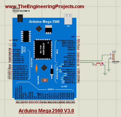
Hello readers! I hope you are doing great. Today, we are discussing the latest library for proteus. In the tutorial, we will look at the Arduino Mega 2560 library for Porteus V 3.0, which is one of the most versatile and useful microcontrollers from the Arduino family. We have shared the previous versions with you before this; these were the Arduino Mega 2560 library for Proteus and the Arduino Mega 2560 library for Proteus V2.0. The current version is better in structure and does not have a link to the website so you may use it in your projects easily. 

Here, I will discuss the detailed specifications of this microcontroller. After that, I will show you the procedure to download and install this library in the Proteus and in the end, we’ll create a mini project using this microcontroller. Here is the introduction to the Arduino Mega 2560:

Where To Buy?
No.ComponentsDistributorLink To Buy
1BuzzerAmazonBuy Now
2Arduino Mega 2560AmazonBuy Now

Introduction to the Arduino Mega 2560 V3.0

The Arduino Mega 2560 belongs to the family of Arduino microcontrollers and is one of the most important devices in embedded systems. Here are some of its specifications:

Specification

Value

Microcontroller

ATmega2560

Operating Voltage

5V

Input Voltage (recommended)

7-12V

Input Voltage (limit)

6-20V

Digital I/O Pins

54 (of which 15 provide PWM output)

Analog Input Pins

16

DC Current per I/O Pin

20 mA

DC Current for 3.3V Pin

50 mA

Flash Memory

256 KB (8 KB used by bootloader)

SRAM

8 KB

EEPROM

4 KB

Clock Speed

16 MHz

LED_BUILTIN

Pin 13

Length

101.52 mm

Width

53.3 mm

Weight

37 g


Now that we know the basic features of this device, we can understand how it works in Proteus. 

Arduino Mega 2560 V3.0 Library for Proteus

This library is not present by default in Porteus. The users have to download and install it in the Porteus library folder. Click on the following link to start the downloading process:

Arduino Mega 2560 V3.0 for Proteus

Adding Proteus Library File

  • If the downloading process is complete, you can see a zip file in the downloading folder of your system. Click on it.

  • Extract the zip folder at the desired location. 

  • Along with some other files, you can see there are two files with the following names in the zip folder:

  • ArduinoMega3TEP.IDX

  • ArduinoMega3TEP.LIB

  • You have to copy these two files only and go to the folder of the given path:
    C>Program files>Lab centre electronics>Proteus 7 Professional>Library

Note: The procedure to install the same package in Proteus Professional 8 is the same.

Arduino Mega 2560 Library V3.0 in Proteus

Now, the Arduino Mega 2560 V3.0 can be run on your Proteus software. Open your Proteus software or if it was already opened, restart it so the libraries may load successfully. 

  • Click on the “P” button on the left side of the screen and it will open a search box for devices in front of you.

  • Here, type “Arduino Mega 2560 V3.0,” and it will show you the following device:

  • Double-click on it to pick it up.

  • Close the search box and click on the name of this microcontroller from the pick library section present on the left side.

  • Place it in the working area to see the structure of the Arduino Mega 2560 V3.0.

If you have seen the previous versions of this microcontroller in Proteus, you can see that the latest version has some changes in it. The design and colour are closer to the real Arduino Mega 2560. Moreover, it does not have a link to the website and the pins are more realistic. 

Arduino Mega 2560 V3.0 Simulation in Proteus

The workings of the Arduino Mega 2560 V3.0 library can be understood with the help of a simple project. Let’s create one. For this, follow the steps given here:

  • Go to the “pick library” again and get the speaker and buttons one after the other.
  • Arrange the speaker with pin 3 of the Arduino Mega 2560 V3.0 placed in the working area.
  • Similarly, place the button on pin 2 of the microcontroller. The screen should look like the following image:

  • Now, go to terminal mode from the leftmost and place the ground terminals with the components.

Now, connect all the components through the connecting wires. Here is the final circuit:

Now, it's time to add code to the simulation.

Code for Arduino Mega 2560 V3.0

  • Start your Arduino IDE.
  • Create a new project by going into sketch>new sketch.
  • Delete the present code from the project.
  • Paste the following code into the project:

const int buttonPin = 2;    // Pin connected to the button

const int speakerPin = 3;   // Pin connected to the speaker

int buttonState = 0;        // Variable to store the button state

boolean isPlaying = false;   // Variable to track whether the speaker is playing

void setup() {

  pinMode(buttonPin, INPUT);

  pinMode(speakerPin, OUTPUT);

}

void loop() {

  // Read the state of the button

  buttonState = digitalRead(buttonPin);

  // Check if the button is pressed

  if (buttonState == HIGH) {

    // Toggle the playing state

    isPlaying = !isPlaying;

    // If playing, start the speaker

    if (isPlaying) {

      digitalWrite(speakerPin, HIGH);

    } else {

      // If not playing, stop the speaker

      digitalWrite(speakerPin, LOW);

    }

    // Add a small delay to debounce the button

    delay(200);

  }

}

  • You can get the same code from the zip file you have downloaded from this tutorial. 

  • Click on the "verify" button present on the above side of the code. 

  • Once the loading is complete, click on the “upload” button present just at the side of the verify button. It will create a hex file in your system. 

  • From the console of loading, search for the address of the file where the code is saved. 

  • In my case, it looks like this:

Copy this path to the clipboard. 

Add the Hex File in Proteus

  • Once again, go to your Proteus software. 

  • Click on the Arduino Mega 2560 to open its control panel. 

  • Paste the path of the hex file in the place of the program file:

  • Hit the “OK” button to close the window.

Arduino Mega 1280 V3.0 Simulation Results

  • Once you have loaded the code into the microcontroller, you can now run the project. 

  • At the bottom left side of the project, you can see different buttons, click on the play button to run the project. 

  • Before clicking on the button of the project, the project looks like the following:

  • Once the button is pressed, you will hear the sound from the speaker. Hence, the speaker works with the button. 

If all the above steps are completed successfully, you will hear the sound of the speaker. I hope all the steps are covered in the tutorial and you have installed and run the Arduino Mega 2560 v3.0 in Proteus, but if you want to know more about this microcontroller, you can ask in the comment section.


Arduino Mega 1280 Library for Proteus V3.0

Hello friends! I hope you are doing great. Today, we are discussing the latest version of the Arduino Mega 1280 library for Proteus. This can be used in both versions (Proteus 7 and Proteus. We have shared the previous versions, which are the Arduino Mega 1280 library for Proteus and the Arduino Mega 1280 library for Proteus V2.0 with you. With the advancement in the version, these microcontrollers have a better structure and the design is closer to the real microcontrollers. 

In this article, I will discuss the introduction of the Arduino Mega 1280 in detail. Here, you will learn the features and functions of this microcontroller. Then, we’ll see how to download and install this library in Proteus. In the end, we’ll see a mini project using the Arduino Mega 1280 V3.0. Let’s move towards our first topic:

Where To Buy?
No.ComponentsDistributorLink To Buy
1Battery 12VAmazonBuy Now
2ResistorAmazonBuy Now
3LCD 20x4AmazonBuy Now

Introduction to the Arduino Mega 1280 V3.0

  • The Arduino Mega is a microcontroller board that is based on the ATmega 1280. It has a large structure and provides more I/O pins.
  • It has the following memory features:
  • 128KB of flash memory to store the programs in it.
  • 8KB of SRAM for dynamic memory allocation
  • 4KB of EEPROM for data storage
  • It has 54 digital pins, of which 14 are used as PWM outputs.
  • It has 16 analogue input pins
  • This microcontroller uses the ATmega16U2 microcontroller for USB-to-serial conversion
  • It has compatibility with Arduino IDE where it is programmed with C++ just like other Arduino boards.
  • One must know that the Arduino Mega 1280 V3.0 is an open-source microcontroller and it is a robust platform for building and experiencing a vast range of electronic projects.

Now, let’s see the Arduino Mega 1280 library V3.0 in Porteus. 

Arduino Mega 1280 V3.0 Library for Proteus

The download and installation process for Arduino Mega 1280 is easy. The Proteus software does not have this library by default. To use it, the first step is to download it from the link given below:

Arduino Mega 1280 V3.0 for Proteus

Adding Proteus Library File

  • The downloading does not take much time. Once it is complete, it can be seen in the download folder on your system.

  • You will see a zip file when it is extracted to a particular path of your choice. 

  • There are two files in the folder named:

    • ArduinoMega3TEP.IDX

    • ArduinoMega3TEP.LIB

  • Copy these files and paste them into the folder with the following path:
    C>Program files>Lab centre electronics>Proteus 7 Professional>Library

Note: The same process is applicable to Proteus 8 professional if you are using that.

Arduino Mega 2560 Library V3.0 in Proteus

  • If all the above steps are completed successfully, the Proteus has to start/restart so that it may load all the files.
  • The Arduino Mega 1280 V3.0 is present in the libraries so click on the “P” button at the left side of the screen to pick it from the libraries. It will open a search box in front of you.
  • Type “Arduino Mega 1280” there and you will see the following options in front of you:

  • Double-click on its name to pick it.
  • Now, click on the picked Arduino Mega and place it on the working area to see its structure:

You can see it has many pins and the structure and design are closer to the real Arduino Mega. There is no link to the website on this microcontroller and it has more details about the pins on it. These points are different from the previous versions. 

Arduino Mega 1280 V3.0 Simulation in Proteus

The Arduino Mega 1280 has many features and it is used in a great number of projects. But, as a beginner, we’ll check the work with the help of a simple project. In this project, we’ll use the LED with Arduino Mega 1280 V3.0 and print the message of our own choice. Follow the steps to perform this example:

  • Go to the pick library once again and write “LCD 20X4 TEP” there. Pick it to use it.
  • Similarly, pick the potentiometer by searching “POT-HG” in the search box.
  • Now, get the “Button” from the same search box.
  • Place the components of the project in the working area by following the pattern given here:

Go to the terminal mode from the left side of the screen, and then choose the default pins for the clean circuit. 

Set and label the pins according to the image given here:

The circuit is fine but it can’t be run without coding.

Code for Arduino Mega 1280 V3.0

  • Fire up your Arduino IDE.

  • Create a new sketch for this project. 

  • The upper side has a drop-down menu, choose Arduino from there. 

  • Delete the default code. 

  • Paste the following code into it:

#include

//Setting the LCD pins

LiquidCrystal lcd(13, 12, 11, 10, 9, 8);

const int buttonPin = 0;

boolean lastButtonState = LOW;

boolean displayMessage = false;


void setup() {

  pinMode(buttonPin, INPUT);

  //Printing the first message

  lcd.begin(20, 4);

  lcd.setCursor(1, 0);

  lcd.print("Press the button to see the message");

}


void loop() {

  int buttonState = digitalRead(buttonPin);

// Using if loop to create the condition

  if (buttonState != lastButtonState) {

    lastButtonState = buttonState;


    if (buttonState == LOW) {

      displayMessage = true;

      lcd.clear();

      lcd.setCursor(1, 0);

      //Printing the message on screen when buttin is pressed

      lcd.print("www.TheEngineering");

      lcd.setCursor(4, 1);

      lcd.print("Projects.com");

    } else {

      displayMessage = false;

      lcd.clear();

      lcd.setCursor(1, 0);

      lcd.print("Press the button to see the message");

    }

  }

}

  • The same code is also present in the zip file of the Arduino Mega 1280 V3.0 library folder you have downloaded. 

  • Click on the tick mark to run the code. It will take some moments to be loaded.

  • Once the loading is complete, click on the upload button to get the hex file address.

  • In the loading process, you have to search for the path to the hex file. In my case, it looks like the following image:

Add the Hex File in Proteus

  • Go to the proteus where we have created our project.

  • Double-click on the Arduino Mega 1280 V3.0 module.  It will open its properties panel in front of you. 

  • Paste the address of the hex file into the section named “Program File.".

  • Hit the “OK” button and close the window.

Arduino Mega 1280 V3.0 Simulation Results

  • There are some buttons at the bottom left corner of the screen. Out of these, you have to click the play button to run the project. 

  • If all the above procedures are completed successfully, you will see the output on the screen. 

  • When the button is opened, the LCD shows the message that you have to push the button to see the message.

  • Click on the button, and now you can see the message on the LCD. 

If all the above steps are completed successfully, you will see that you have used the Arduino Mega 1280 V3.0 to show the required message on the LCD. This microcontroller can be used in different complex projects and can provide the basic working according to the code. Now, you can try different projects on your Proteus. I hope you have installed the microcontroller successfully. Yet, if you are stuck at any point, you can ask in the comment section.

Arduino Pro Mini Library for Proteus V3.0

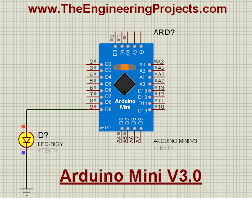
Hello friends! I hope you are doing great. Today, we are presenting another version of the Arduino Pro mini library. We have seen the Arduino Pro Mini library for Proteus and the Arduino Pro Mini library for Proteus V2.0 with you. As expected, the Arduino Mini Library for Proteus V3.0 has a better structure and size that make it even better than the previous ones. We will go through the details of the features to understand the library. 

In this article, I will briefly discuss the introduction of Arduino Pro Mini V3.0. You will learn the features of this board and see how to download and install this library in Proteus. In the end, I will create and elaborate on a simple project with this library to make things clear. Let’s move towards our first topic:

Where To Buy?
No.ComponentsDistributorLink To Buy
1Battery 12VAmazonBuy Now
2LEDsAmazonBuy Now
3ResistorAmazonBuy Now
4Arduino Pro MiniAmazonBuy Now

Introduction to the Arduino Pro Mini V3.0

In the vast range of microcontrollers, the Arduino Pro mini stands as the most powerful and compact member of the Arduino family. With the advancement in the version, the better functionalities and easy working of this microcontroller have been seen. Here are some important features of this microcontroller:

  • It has a compact size; therefore, it is named so. It has an even smaller size than the Arduino Mini. The minimalist design allows this board to adjust in compact spaces.
  • It has a simple structure and can be used with uncomplicated circuits.
  • The Arduino Pro Mini V3.0 also uses the ATmega328P, as the Arduino UNO does. It is the reason why it is considered a perfect balance between the small size and the powerful structure of the other basic Arduino microcontrollers.

  • It can be operated at different voltage levels, making it versatile for different types of projects. It can be operated at a wide range between 3.35V and 12V. This makes it ideal for battery-oriented projects as well as for large projects.
  • It has a smaller size but it is designed to accommodate 22 pins, which are:
  • 14 digital pins
  • 8 analogue pins
  • It has a large community; therefore, there is a great scope for this board and users can easily get the help of the experts.

Now, let’s see the Arduino Pro Mini library V3.0 in Porteus. 

Arduino Pro Mini Library for Proteus V3.0

By default, the Proteus does not have any Arduino Pro mini library. This can be used in Proteus by installing it manually. For this, download the library through the link given next:

Arduino Pro Mini Library for Proteus V3.0

Adding Proteus Library File

  • Once the downloading process is complete, you can see a zip folder with the same name in your download folder. Double-click on it or extract the file to the current folder with any other method. Remember the path to this extracted file. 

  • Now, go to the required path and open the folder named “Proteus Library Files.”. 

  • Here, you will find the following files:

    • ArduinoProMini3TEP.IDX

    • ArduinoProMini3TEP.LIB

  • These folders have to be placed in the library folder of Proteus so that we can have them in Proteus. 

  • For this, follow the path C>Program files>Lab centre electronics>Proteus 7 Professional>Library. Simply paste both of these into the folders of other libraries.

Note: The procedure to add the same library to Proteus 8 is the same. 

Arduino Pro Mini Library V3.0 in Proteus

  • If you have followed the above procedure successfully, the Arduino Pro mini V3.0 will work in your Proteus. If the software was already open, restart it. Otherwise, open your Proteus software. 

  • Click on the P button on the left side of the screen. This will prompt you to enter the search box.

  • Here, search for “Arduino Pro Mini V.30,” and if you have installed it successfully, you will see it in the options:

  • Click on the name “Arduino Pro Mini V3.0.”. It will be shown in the Pick Library of your Porteus.

  • Click on the name of this microcontroller and double-click on the working area to fix it there.

  • Look at the structure and pinouts of this Arduino board.

You can see this version has a better structure of pins and is similar to the real Arduino Pro Mini. We have removed the link to the website from this library and created an even smaller Arduino Pro Mini so the users can have a better experience with it. 

Arduino Pro Mini V3.0 Simulation in Proteus

It’s time to test the workings of this microcontroller in Porteus.

Fading LED with Arduino Pro Mini V3.0

  • The components are required for the creation of the whole project. For this, go to the “Pick library” through the same “P” button.
  • In the search box, type LED, grab it and repeat the instructions for the resistor.
  • Set the components in the working area. The proteus must look like the following image:

  • Connect one side of the LED to digital pin 2 of the Arduino Mini.
  • Connect the other side of the resistor with the LED terminal.
  • Double-click on the resistor to change its value. I’ll manually set it to 330 ohms.
  • From the leftmost side of the menu, search for terminal mode.
  • Here, search for the ground terminal and choose it.
  • Connect this terminal to the other end of the resistor.
  • Now, the project is ready to be played:

This will not work until we program the Arduino pro Mini in Arduino IDE.

Code for Arduino Pro Mini V3.0

  • Open your Arduino IDE in your system.
  • Create a new sketch for this project.
  • Select the right board and port. You have to select Arduino UNO from the board menu.

  • Delete the existing code and paste the following one there:

int LED = 2;         // the PWM pin the LED is attached to

int brightness = 2;  // how bright the LED is

int fadeAmount = 5;  // how many points to fade the LED by

void setup() {

  // declaring pin 9 to be an output:

  pinMode(LED, OUTPUT);

}

void loop() {

  // setting the brightness of pin 9:

  analogWrite(led, brightness);

  // changing the brightness for next time through the loop:

  brightness = brightness + fadeAmount;

  // reversing the direction of the fading at the ends of the fade:

  if (brightness <= 0 || brightness >= 255) {

    fadeAmount = -fadeAmount;

  }

  // waiting for 30 milliseconds to see the dimming effect

  delay(50);

}

}

  • You can have the same code in the zip file you downloaded before through this article. Click on the tick mark at the above side of the screen. 

  • Wait for the loading to complete. 

  • Click on the “Upload” button next to the tick mark. The loading will start at the bottom and you will see the hex file in the console. 

  • Search for the whole address of the hex file to copy it.

Add the Hex File in Proteus

  • The previous process created a hex file in your system. You have to redirect Prteus to that file. For this, go to the Protwus software where you have created the project.
  • Double-click on the Arduino Pro Mini V3.0. A dialogue box will appear on the screen.
  • Paste the address of the hex file to the empty section named "Program file".

  • Hit the “OK” button to save the settings.

Arduino Mini V3.0 Simulation Results

  • Now, the project is ready to be played. Hit the play button to start the simulation. 

  • If all the components are set up well and the project does not have any errors, the simulation will be started.

If all the steps are accomplished completely, your project will run successfully. I hope you have installed and worked with the Arduino Pro mini V3.0 without any errors and you can now create complex projects with this. Still, if you are stuck at any point, you can ask in the comment section.


Reasonable Solutions to the Top 10 Challenges to Meeting Project Deadlines

Meeting project deadlines doesn't have to feel like a race against time. With meticulous planning, effective communication , innovative tools, and realistic expectations; you can consistently meet your project deadlines without anxiety and ensure smooth project execution.

This article will walk you through the solutions and strategies necessary for overcoming challenges that are thrown your way while working toward a deadline. It won’t matter if you’re on your final year project or providing a small deliverable to a client, as the subsequent sections offer insights that should help everyone achieve these ends more efficiently and stress-free.

10 Solutions to Challenges Regarding Meeting Project Deadlines

Navigating through project management can be a challenging task. Let's delve into 10 practical solutions that can ease this burden and ensure your projects consistently meet their deadlines.

1. Outline Your Projects, Goals, and Deadlines

It’s vital to have a clear understanding of your project objectives before diving into operating tasks. Begin by outlining your projects, detailing goals , and establishing deadlines. This will give you a bird's eye view of what needs to be accomplished and when it ought to be finished.

Having this roadmap in place ensures that everyone on the team is aligned towards the same goal, and moving at the same pace. It also acts as a tool for measuring progress at any given time, alerting you beforehand if there's an impending delay needing your attention.

2. Use a Project Management Tool

In this digital era, using a project management tool can be a game-changer for meeting your project deadlines. These tools can significantly streamline project planning, task delegation, progress tracking, and generally increase overall efficiency—all centered in one place.

You can automate workflows, set reminders for important milestones or deadlines, and foster collaboration by keeping everyone in sync. The aim here is to simplify the process of handling complex projects from start to finish and aiding to consistently meet deadlines without hiccups.

3. Adopt Engagement and Rewards Software

When stuck in a project timeline conundrum, consider making use of engagement software for thriving employees . This specialized type of software enables you to track your team's progress effectively and realize their full potential, as it rewards productive project-based behaviors.

In addition to this, it facilitates seamless communication between different members, which leads to efficient problem resolution. By making your team feel appreciated and acknowledged, you pave the way for faster completion of tasks and adherence to project deadlines.

4. Break Projects Into Smaller Chunks

Large, complex projects might seem intimidating or even overwhelming at first glance. A constructive way to manage these is by breaking down the project into smaller, manageable chunks. This method often makes tackling tasks more feasible and less daunting.

Each small task feels like a mini project on its own, complete with its own goals and deadlines. As you tick off each finished task, you'll gain momentum, boost your confidence, enhance productivity, and gradually progress toward meeting the overall project deadline.

5. Clarify Timelines and Dependencies

Understanding and aligning project timelines and dependencies is key to successful deadline management. Be clear about who needs to do what, by when, and in what sequence. Remember that one delayed task can impact subsequent tasks, leading to a domino effect.

Clarity on these interconnected elements helps staff anticipate their upcoming responsibilities and also helps manage their workload efficiently. Proactively addressing these dependencies in advance can prevent any unexpected obstacles from derailing your progress.

6. Set Priorities for Important Tasks

Deciding priorities for tasks is crucial in project management, especially when you're up against pressing deadlines. Implementing the principle of 'urgent versus important' can be insightful here. High-priority tasks that contribute to your project goals should get immediate attention.

However, lower-priority ones can wait. This method helps ensure vital elements aren't overlooked or delayed due to minor, less consequential tasks. Remember, being effective is not about getting everything done. It's about getting important things done on time. 

7. Account for Unforeseen Circumstances

You can plan meticulously, but unpredictable circumstances could still cause setbacks. Whether it’s technical hitches, sudden resource unavailability, or personal emergencies, numerous unforeseen factors could potentially disrupt the project timeline and affect your deadline.

Therefore, factoring in a buffer for these uncertainties when setting deadlines is wise. This doesn't mean you can slack off or procrastinate. Instead, be realistic about the potential challenges and try to be flexible in adapting to changes swiftly when they occur. 

8. Check-in With Collaborators and Partners

Interactions with collaborators and partners help gauge progress, identify bottlenecks, discuss issues, and brainstorm solutions in real time. This collaborative approach encourages a sense of collective responsibility toward the project, keeping everyone accountable and engaged.

Regular communication ensures that everyone is on the same page, minimizing misunderstandings or conflicts that could stall progress. By fostering a culture of open, transparent dialogue, you're much more likely to track steadily towards your project deadlines.

9. Ensure Hard Deadlines are Achievable 

Setting hard deadlines certainly underpins project planning, but these must be practical and achievable. Overly ambitious timelines can result in hasty, incomplete work or missed deadlines. Start by reviewing past projects to assess how long tasks actually take to establish a base.

Additionally, consult with your team about time estimates, as they often have valuable frontline insights into what's feasible. Aim for a balance, such as a deadline that is challenging, but doesn't overwhelm. This will foster motivation while maintaining the quality of deliverables.

10. Do Your Best to Avoid Scope Creep

Scope creep is the phenomenon where a project's requirements increase beyond the original plans, often leading to missed deadlines. It's triggered when extra features or tasks are added without adjustments to deadlines or resources. To avoid it, maintain a clear project scope.

Learn to say “no” or negotiate alternative arrangements when new requests surface mid-project. While flexibility is important, managing scope creep efficiently ensures that additions won't derail your timeline, keeping you on track toward successfully meeting your project deadlines.

In Conclusion… 

Now that you're equipped with these solutions, it's time to put these strategies into action. Remember, occasional hiccups and delays are a part of every project's life cycle, but they shouldn't deter you. Stay realistic, adapt as needed, and keep up the good work!

Arduino Mini Library for Proteus V3.0

Hello friends! I hope you are doing great. Today, we are discussing the most upgraded version of the Arduino Mini in Porteus. Before this, we have shared the Arduino Mini library for Proteus and the Arduino Mini library for Proteus V2.0 with you. The Arduino Mini Library for Proteus V3.0 has a better structure and has some other changes that make it even better than the previous ones. This will be clear when you see the details of this library.

In this article, I will briefly discuss the introduction of Arduino Mini. You will learn the features of this board and see how to download and install this library in Proteus. In the end, I will create and elaborate a simple project with this library to make things clear. Let’s move towards our first topic:

Where To Buy?
No.ComponentsDistributorLink To Buy
1Battery 12VAmazonBuy Now
2LEDsAmazonBuy Now
3ResistorAmazonBuy Now
4Arduino Pro MiniAmazonBuy Now

Introduction to the Arduino Mini

The Arduino Mini is a compact board created under the umbrella of Arduino.cc specially designed for projects where the space is limited. 

It was introduced in 2007 and it has multiple variants since then.  

  • This board is equipped with the Atmel AVR microcontroller such as ATmega328P. and is famous for its low power consumption. 

  • It has limited digital and analogue input/output pins and its specifications make it suitable for the IoT, robotics, embedded systems and related industries. 

  • This board has different types of pins that include:

    • 14 digital pins 

    • 8 analogue I/O pins

    • Power pins, including 5V, 3.3V, and VIN (voltage in)

    • Ground pin GND (ground)

Just like other Arduino boards, the Arduino mini is also programmed in Arduino IDE.

Now, let’s see the Arduino Mini library V3.0 in Porteus. 

Arduino Mini Library for Proteus V3.0

You will not see the Arduino Mini library for Proteus V3.0 in Proteus by default. We have designed these libraries and they can be easily installed by following these simple steps.

  • First of all, click on the below link and download the library.

Arduino Nano Library for Proteus V3.0

Adding Proteus Library File

  • Once the file is downloaded, you will see its zip folder in the download folder.
  • Extract the file to the current folder or to your desired location.
  • Now, go to the location of the folder and open the folder named “Proteus Library Files”.
  • Here, you will find the following files:
  • ArduinoMini3TEP.IDX
  • ArduinoMini3TEP.LIB
  • These files have all the required functionalities but we have to paste them in the library folder of the Porteus software.
  • For this, follow the path C>Program files>Lab centre electronics>Proteus 7 Professional>Library and paste both of these with other libraries.
  • If you want the details of this process, you must see How to Add a New Library File in Proteus.

Note: I am using Proteus Professional 7 in this tutorial but users of Proteus Professional 8 can use the same process for the installation of the library. 

Arduino Mini Library V3.0 in Proteus

  • Once the library is successfully installed in the folder if your Porteus software is already open, restart it to successfully load all the packages.
  • Now, Arduino Mini V3.0 is present in your proteus library folder.
  • Click on the “P” button on the left side of the Proteus screen.
  • Now search for "Arduino Mini V3.0 TEP”.
  • The microcontroller will appear in the search bar.
  • The screen will look like the following image:

  • Click on the Arduino Mini V3.0 and add it to your component window on the left side of the screen.
  • Here, on the component window, click on “Arduino mini V3.0” and drop it on the working area.
  • Look at the structure and pinouts of this Arduino board.

This library has a better design than the previous versions of Arduino Mini. You can see its better pinouts & reduced size. The color of this board is nearer to the real Arduino Mini microcontroller board. I have made it even smaller to accommodate in the complex projects easily. This board does not have the link to our website on its face.

Arduino Mini V3.0 Simulation in Proteus

Now, let’s design the simulation using this updated Arduino Mini.

Fading LED with Arduino Mini V3.0

  • Go to the “Pick library” button.
  • Search for LED and resistor one after the other.
  • Connect one side of the resistor to digital pin 9 of the Arduino Mini.
  • Connect the other side of the resistor with the LED terminal.
  • Double-click on the resistor to change its value to 330 ohms. You have to do it manually.
  • Search for the terminal mode on the left side of the screen.
  • Click on it and you will see different components.
  • Choose the “Ground” terminal.
  • Connect this terminal to the other end of the LED.
  • The project must look like this:

Code for Arduino Mini V3.0

  • Open the Arduino IDE.
  • Click on the “Board” section and select the Arduino board from the drop-down menu.
  • Delete the present code of the screen.
  • Paste the following code into it:

int LED = 9;         // the PWM pin the LED is attached to

int brightness = 2;  // how bright the LED is

int fadeAmount = 5;  // how many points to fade the LED by

void setup() {

  // declaring pin 9 to be an output:

  pinMode(LED, OUTPUT);

}

void loop() {

  // setting the brightness of pin 9:

  analogWrite(led, brightness);

  // changing the brightness for next time through the loop:

  brightness = brightness + fadeAmount;

  // reversing the direction of the fading at the ends of the fade:

  if (brightness <= 0 || brightness >= 255) {

    fadeAmount = -fadeAmount;

  }

  // waiting for 30 milliseconds to see the dimming effect

  delay(50);

}

}

  • I will add the same code to the zip file of the library. Now, compile the code through the “Verify” button.
  • Wait for the loading process to complete.
  • Click on the “Upload” button. The loading will start at the bottom and you will see the hex file in the console.
  • Search for the whole address of the hex file to copy it.

Add the Hex File in Proteus

  • Double-click on the Arduino Mini V3.0 module in Proteus and the properties window will appear in front of you.
  • Paste the hex file of the project in the empty section named “Program file”.
  • Hit the “OK” button and close the window.

Arduino Mini V3.0 Simulation Results

  • The play button on the lower left side of the screen is used to start the simulation of the project.
  • If all the components are set well and the project does not have any errors, the simulation will be started.

If you follow all the steps accurately, your project will work fine. You can make the changes in the project with the help of code in the Arduino IDE. As I just want to show you the working of Arduino Mini here, I have chosen one of the most basic projects. But, Arduino Mini can be used for complex projects as well. If you want to ask any questions, you can use the comment box to connect with us.

Arduino Nano Library for Proteus V3.0

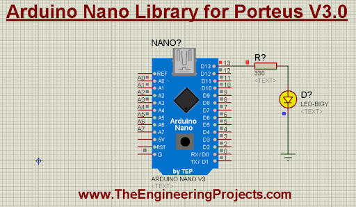
Hello friends! I hope you are doing great. In this tutorial, we are discussing the upgraded version of the Arduino Nano. Before this, we discussed the Arduino Nano library for Proteus and the Arduino Nano library for Proteus V2.0. The new version of the Arduino Nano library for Proteus V3.0 has a better structure and is working better. We will discuss it in detail in just a bit. 

In this article, I will discuss the basic introduction of Arduino Nano. We will learn how to download and install this library in Proteus and will create a simple project with this library. Let’s move towards our first topic:

Where To Buy?
No.ComponentsDistributorLink To Buy
1Battery 12VAmazonBuy Now
2LEDsAmazonBuy Now
3ResistorAmazonBuy Now
4Arduino NanoAmazonBuy Now

What is the Arduino Nano?

  • The Arduino Nano was released in 2008 by Arduino. cc and it is an open-source microcontroller board that has a great scope in the embedded industry.
  • This board is baked on a Microchip ATmega328P and is famous for its low power consumption and versatile working.
  • It is equipped with digital and analog input/output pins and its specifications make it suitable for the IoT and related industries.
  • This board has different types of pins that include:
    • 22 digital pins
    • 8 analogue I/O pins
    • Power pins, including 5V, 3.3V, and VIN (voltage in)
    • Ground pin GND (ground)

Now, let’s see the Arduino Nano library V3.0 in Porteus. 

Arduino Nano Library for Proteus V3.0

The Arduino Nano library for Proteus V3.0 is not present in Proteus by default, but it can be easily installed by following these simple steps. 

  • First of all, download the library by clicking on the following link:

Arduino Nano Library for Proteus V3.0

Adding Proteus Library File

  • The file will be downloaded in the zip folder. Extract the file to your desired location.
  • Once extracted, go to the relevant location and open the folder named “Proteus Library Files”.
  • Here, you will find the following files:
  • ArduinoNano3TEP.IDX
  • ArduinoNano3TEP.LIB
  • Now, copy these files and simply paste them into the library folder of Proteus software, where other libraries are already present.
  • For this, follow the path C>Program files>Labcenter electronics>Proteus 7 professional>Library
  • If you are facing any issues with the installation, you can get help from How to Add a New Library File in Proteus.

Note: The procedure to use this library in Proteus 8 Professional is the same. 

Arduino Nano Library in Proteus

  • Once the library is installed, if your Porteus software is already open, you have to restart it so that Proteus may read the functionality of the library.
  • Now, Arduino Nano V3.0 is present in your Proteus software.
  • Click on the “P” button of the library from the left side of the Proteus screen and search for "Arduino Nano V3.0 TEP,” and it will show you the library.
  • The screen will look like the following image:

  • Double-click on the Arduino Nano V3.0 to add it to your component window.
  • Click on the name of the Arduino and then place it on the working sheet to check the look and pinouts of this Arduino Nano V3.0.

This library has a better design than the previous versions. It has better pinouts and its color is nearer to the real Arduino Nano microcontroller board. It is smaller than the previous versions and most important, it does not have the link to our website on its face. I hope you like it. 

Arduino Nano V3.0 Simulation in Proteus

Once you have seen the pinouts, let’s design the simulation using this board. Here, we will create a basic mini-project where we will see the blinking LED on this board. It is one of the best examples of Arduino working for beginners. Follow the steps to create the project:

LED with Arduino Nano V3.0

  • Once again, go to the “Pick library” button and choose LED and resistor.
  • Connect one side of the resistor to any digital pin of Arduino Nano. I am using pin 13.
  • Connect the LED to the other end of the resistor with the help of connecting wires.
  • Double-click on the resistor to change its value to 330 ohms by simply writing the value manually.
  • Go to terminal mode from the left side of the screen. You will see different components; choose the “Ground” terminal.
  • Connect this terminal to the other end of the LED.

Code for Arduino UNO V3.0

  • The code for this board will be written in the Arduino IDE. Start your Arduino IDE and create a new project.
  • If no board is selected, click on the “Board” section and select the Arduino board from the drop-down menu of the boards.
  • Remove the present code in the file and paste the following code into it:

void setup() {

  // initialize digital pin LED_BUILTIN as an output.

  pinMode(LED_BUILTIN, OUTPUT);

}

//The loop function runs over and over again forever

void loop() {

  digitalWrite(LED_BUILTIN, HIGH);  // turn the LED on (HIGH is the voltage level)

  delay(1000);                      // wait for a second

  digitalWrite(LED_BUILTIN, LOW);   // turn the LED off by making the voltage LOW

  delay(1000);                      // wait for a second

}

  • The same code is also present in the zip file you downloaded before.
  • Compile the code through the “Verify” button. The loading will start at the bottom of the screen in the console window.
  • Now, click on the “Upload” button to get the hex file.
  • Search for the address of the hex file at the bottom of the screen and copy it.

Add the Hex File in Proteus

  • Double-click on the Arduino Nano V3.0 in Proteus to open its properties panel.
  • Paste the address of the hex file you have just copied from the console of your Arduino IDE.

  • Click on the “OK” button to close the window.

Arduino Nano V3.0 Simulation Results

  • Click on the play button at the bottom of the screen to get the results of the simulation.
  • I am sure your LED will start blinking If you have correctly followed all the instructions.

I hope your project is working fine. You can change the timing of the blinking through the code of the Arduino IDE. As I have said earlier, this is the most basic project. If you are facing any issues regarding this library, you can ask in the comment section.

Arduino UNO Library for Proteus V3.0

Hi friends! I hope you are having a good day. Today, I am presenting the Arduino UNO library for Proteus V3.0. You should have a look at the previous versions of this library i.e. Arduino UNO library for Proteus(V2.0) and the Arduino UNO library for Proteus(V1.0). The warm response of the students to these libraries has motivated them to upgrade the library. The latest version of this library has better design and functionality, which I will discuss in detail with you. 

In this article, we will discuss the basic introduction to the Arduino UNO library, its simulation, and its working. Moreover, we will discuss a small project to show you the functionality of this library. Here is the introduction to the library:

Where To Buy?
No.ComponentsDistributorLink To Buy
1Battery 12VAmazonBuy Now
2LEDsAmazonBuy Now
3ResistorAmazonBuy Now
4Arduino UnoAmazonBuy Now

What is the Arduino UNO?

  • The Arduino UNO was released in 2010 by Arduino. cc and it is a microcontroller board that is mostly used in embedded systems.
  • This board is baked on a Microchip ATmega328P and is equipped with digital and analog input/output pins.
  • This board has 14 digital and 6 analog I/O pins, a type B USB cable,  and can be programmed with the Arduino IDE.

Now, let’s see the Arduino UNO library in Porteus. 

Arduino UNO Library for Proteus V3.0

The Arduino UNO library for Proteus V3.0 can be easily installed by following these simple steps. First of all, download the library by clicking on the following link:

Arduino UNO Library for Proteus V3.0

Adding Proteus Library File

  • The file will be downloaded in the zip folder. Extract the file and open the folder named “Proteus Library Files”.
  • There, you will find the following files:
  • ArduinoUNO3TEP.IDX
  • ArduinoUNO3TEP.LIB
  • Copy these files and paste them into the library folder of Proteus software. For this, follow the path C>Program files>Labcenter electronics>Proteus 7 professional>Library
  • If you are facing any issues with the installation, you can read How to Add a New Library File in Proteus .

Note: The procedure to use this library in Proteus 8 Professional is the same. 

Arduino UNO Library in Proteus

  • Once the library is installed, if your Porteus software is open, restart it to read the functionality of the library.
  • Click on the “P” button of the library and search for "Arduino UNO V3.0 TEP,” and it will show you the library. The screen will look like the following image:

  • Pick the Arduino UNO V3.0 by double-clicking on it.
  • From the component window, click on the name of Arduino and then place it on the working sheet to check the look and pinouts of this Arduino UNO V3.0.

Arduino UNO V3.0 Simulation in Proteus

It is time to check the workings of the Arduino library. Here, we will create the simple project of blinking the LED with an Arduino. It is a basic project and the best example of Arduino working for beginners. Follow the steps to create the project:

LED with Arduino UNO V3.0

  • Go to the “Pick library” button and choose LED and resistor.
  • Connect one side of the resistor to pin 13 (or any) of the Arduino.
  • Connect the LED to the other end of the resistor.
  • Double-click on the resistor and change its value to 330 ohms.
  • Go to the terminal mode from the left side of the screen and choose the “Ground” terminal.
  • Connect this terminal to the end of the LED.

Code for Arduino UNO V3.0

  • Open your Arduino IDE to write the code in it.
  • Select the Arduino board from the drop-down menu of the boards.
  • Create your own code or simply paste the following code into it:

void setup() {

  // initialize digital pin LED_BUILTIN as an output.

  pinMode(LED_BUILTIN, OUTPUT);

}

//The loop function runs over and over again forever

void loop() {

  digitalWrite(LED_BUILTIN, HIGH);  // turn the LED on (HIGH is the voltage level)

  delay(1000);                      // wait for a second

  digitalWrite(LED_BUILTIN, LOW);   // turn the LED off by making the voltage LOW

  delay(1000);                      // wait for a second

}

  • Compile the code by clicking on the tick mark. The loading will start at the bottom of the screen.
  • Copy the address of the hex file from the bottom of the screen.

Add Hex File in Proteus

  • There is a need to create a connection between Arduino in Proteus and the Arduino IDE.
  • Double-click on the Arduino UNO V3.0 in Proteus to open the properties panel.
  • Paste the address of the hex file copied from the Arduino IDE.

Arduino UNO V3.0 Simulation Results

  • Click on the run button to get the results of the simulation.
  • If you have correctly followed all the instructions, then the LED will start blinking.

I hope your project is working fine. This is the most basic project, and you can see the Arduino UNO library for Proteus V3.0 has perfect functionality. If you are facing any issues regarding this library, you can ask in the comment section. 

Emerging Trends in PCB Technology

Printed circuit boards are the most important and basic component of the electronic industry. These boards have made it possible to create and run circuits on every level and have served as the backbone of any electronic device. With the growing demand for technology, PCBs have gone through multiple evolutions. The transformation of PCBs has made it possible to create innovative and better electronic circuits.

Today, we are talking about the emerging trends in PCB that are reshaping electronic circuits and the components used in innovative designs. But before this, it is important to understand the importance of using the emerging trends for the circuits.

Importance of Using Trending Technologies in PCBs

PCBs are versatile components, and not all PCBs are ideal for a particular type of circuit. However, it is always advisable to use the most trending technologies to meet the needs of the time, especially in the case of designing Multilayer PCB. Here are some important and obvious advantages to using the trending technologies:

Enhanced Performance

The enhanced technologies are made to provide better functionality and performance. The researchers are working on providing the best techniques to make the lower PCBs work more efficiently, even on low power. Experiments are being performed on different materials to improve electricity flow and resistance to heat.

Similarly, multiple techniques are introduced to reduce the size of components and boards to provide better accommodation for components in the boards. As a result, more components can be settled on the same board, and better performance is expected.

Reliable Results

The advanced technology is more reliable because of the multiple experiments and research performed on PCBs. The advanced PCBs have a lower risk of failure and other related factors, and they have a longer life as compared to the older technology PCBs. For instance, in the latest PCBs, lead-free solder and other safe materials are used to ensure reliable working for a long time. Moreover, conformal coating is used as a coating to provide protection to the PCB against moisture, dust, and other contaminants that can harm the PCBs.

Versatility in PCBs

The advanced technology provides more versatility and variety in operations related to PCB functionalities. For instance, 3D printing technologies allow the user to create complex and smaller PCB designs that were almost impossible with the old and traditional techniques. For instance, laser direct imaging technology helps to improve the accuracy of PCBs; therefore, multiple operations can be performed on such PCBs with a lower risk of damage.

Emerging Trends in PCB Technology

Technology is all about following the trends that people want. In the electronic industry, trends do not change rapidly, but there is still a need to follow the emerging and latest technologies to match the requirements of devices and for better component selection. Here are some trends that are present in the market for PCB and have scope in the future as well.

Flex and Rigid-flex PCBs

The material of the PCB is the most obvious and important factor to consider when choosing the type of board. Flexible PCBs are trending in the market because of their ability to adjust to different shapes and inconvenient places. The market for electronic devices requires a type of PCB that can fit into wearables and other small places and can accommodate the shape of the latest devices. People are moving towards flexible and rigid-flex PCBs because they are convenient, reliable, and durable, even in challenging situations. 

It has been seen that flex and flex-rigid PCBs have more life than simple hard and inflexible boards. Moreover, these PCBs can accommodate a larger number of components because the electrical traces are flexible and can conduct electricity at a longer distance. It is evident that the electricity in these PCBs faces low resistance therefore, the conductivity is enhanced. 

Miniaturization and HDI PCBs

This is the era where everything can be made better using different technologies. Wearable devices are trending, and this has led to the success of miniaturization and HDI PCBs. Miniaturization not only makes the PCB smaller, but these are more powerful versions of the bigger PCBs because of the advanced technologies and best material used for electrical conductivity. 

In small PCBs, high-definition interconnections are used for the best electrical conductivity and traces. These microvalves and multiple-layer PCBs provide better performance and are one of the most trending PCBs in the industry. 

3D Printing 

3D printing is the emerging trend in prototyping, and it provides convenience during the design process. It is used to create the conductive traces within the multi-layer intricate PCBs. This has made rapid customization and provided variety for prototyping and ideal design formation in PCBs. People are moving towards this technology because it allows them to use their creativity and make possible results. PCBWay is one of the best PCB Fabrication houses and provides the best 3D printing.

Quantum Dots and Nanotechnology

Quantum dots and nanotechnology are the trending technologies for the devices for medical industry and display applications. These are the tiny semiconductor particles used in the PCBs and provide different colours and lights when the electricity is passed through them. Such types of PCBs are trending in the advertising, market, and medical industries, where attractive and unique colours are required to distinguish different elements.

Smart PCBs for IoT

The integration of IoT technology into the PCBs is making them smarter. These PCBs are the heart f the connected world and require communication between different devices. IoT provides the functionality of different wireless communication and connections with the help of different controllers, sensors, modules, etc that enable the devices to collect and transmit the data. These smart PCBs provide automation and create the smart networks that are trending in every field.

Best PCB Company Working on the Latest Techniques

The first step in innovative electronics is the application of the latest techniques to the PCBs. It seems PCBWay Fabrication House knows it very well because it has been working on emerging technologies to provide the latest functionalities in its PCBs. It is a Chinese company that started in 2003 and since then, it has gained a great number of customers and provides its services almost all over the world through its website. It seems like the motto of this company is to win the hearts of customers all over the world through their high-quality and affordable products and services.

This company has manufacturing facilities in multiple countries, including Shenzhen and China and the sales and support network of PCBWay makes it one of the most reliable companies around the world.

Innovative Techniques of PCBWay

PCBWay is committed to providing the exact product according to the customer’s expectations. It offers multiple types of plates, including Rogers, copper substrates, aluminium substrates, high-frequency high-speed HDI for miniaturization and other latest techniques. The following is a list of the basic techniques PCBWay uses to provide trending products and services:

  1. impedance control

  2. HDI blind buried hole

  3. Thick copper PCB

  4. Multi-layer special stack-up structure

  5. Electroplated nickel gold/gold finger

  6. Electroless Nickel Electroless Palladium Immersion Gold (ENEPIG)

  7. Shaped holes

  8. Deep Groove

You can get details on each of them here . The research department of this company works day and night to provide innovative and demanding products when the customer contacts them for an order or suggestions. 

Bottom Line

Printed circuit boards have to be more versatile and up-to-date all the time to meet the needs of the technical world. These are the backbones of the electronic industry, and the competition among different companies makes it compulsory to use trending technologies in PCBs. We have seen why it is important to use the latest technology in the PCB and what some basic and trending technologies are. In the end, we have discussed one of the most popular companies, PCBWay, for the prototyping, manufacturing, and related tasks on the PCBs, and we have discussed some of the basic techniques it follows. I hope it was information for you.

Syed Zain Nasir

I am Syed Zain Nasir, the founder of <a href=https://www.TheEngineeringProjects.com/>The Engineering Projects</a> (TEP). I am a programmer since 2009 before that I just search things, make small projects and now I am sharing my knowledge through this platform.I also work as a freelancer and did many projects related to programming and electrical circuitry. <a href=https://plus.google.com/+SyedZainNasir/>My Google Profile+</a>

Share
Published by
Syed Zain Nasir