Traffic Light Circuit using 555 Timer in Proteus

Hey pals! Welcome to the board. We are talking about a fascinating experiment about The Engineering Projects. We all know about the Traffic Lights. But today, we'll see inside the Traffic Lights and find some interesting working of the circuit of Traffic Lights. Before this, just have a look at the topics of discussion:

  1. What is the Traffic Lights circuit with 555 Timer?
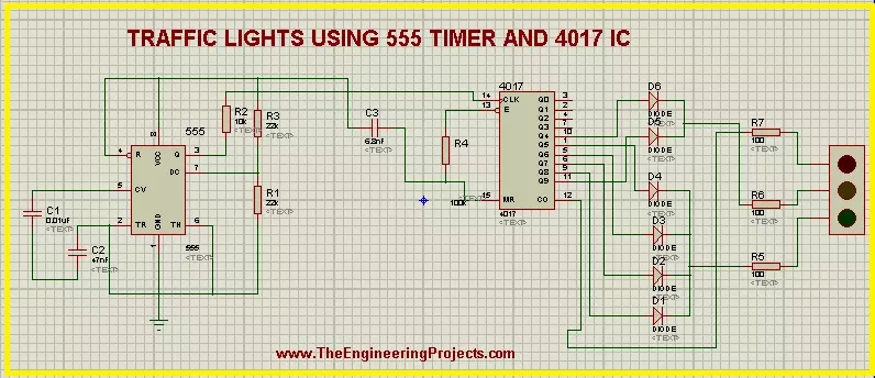
  2. What does the 555 timer do in Traffic Lights?
  3. What is the purpose of the 4017 IC Counter in the circuit?
  4. How does the circuit of Traffic Lights work with 555 Timer IC?
  5. How can we perform experiments with the circuit of 555 Timer Traffic Lights in Proteus ISIS?

In addition, we'll see some important points about the topic in DID YOU KNOW sections.

Traffic Lights circuit with 555 Timer

Whenever we rush toward any road that has a heavy flow of vehicles, we always follow some traffic rules. One of the most fundamental traffic rules is to follow the traffic lights. These traffic lights direct the vehicles to start or stop moving at the road according to our turn. These turns are decided by the Traffic Lights. The traffic Lights show the different colored lights and these lights turn on and off in a sequence. We know all these things, but we are revising these to get the logic behind the scene. we define the Traffic Lights technically as:

"The traffic lights are the combination of three LEDs colored as red, amber and green that are connected in a specialized circuit that gives the output from the LEDs in a specific format and this format is used to control the flow of traffic."

These LEDs are enclosed in a metallic body. Traffic Light signals are so useful that 99% of the countries use them. This makes the circuit one of the most fundamental and common circuits to understand.

There are many devices through which the Traffic Lights may be controlled. Out of which, two are common:

  1. Traffic Lights with the D Flip Flop.
  2. Traffic Lights with 555 Timer

We have discussed the 1st method in our previous tutorial, Let's have a look at the next one.

555 Timer IC Performance in Traffic Lights

before starting the simulation, let's have a look at its components briefly. The circuit of Traffic Lights uses a very common yet powerful device i.e, 555 Timer IC. The 555 Timer is so useful that it is said that annually, a billion of 555 Timers are produced and it is considered as the most popular IC of the year 2017. We introduce the 555 Timer as:

"The 555 Timer is a common 8 pins Integrated Circuit used in a variety of oscillation generators and Timers to generate a pulse of the signals that control the output sequentially."

In our experiment, we'll apply the Mono-stable Multi-vibrator mode of the 555 timer. The output of 555 Timer in this mode is in the form of a single pulse of current that has a specific length. This pulse is sometimes called the one-shot pulse.

4017 IC in the 555 Timer Traffic Lights

The 4017 is the special IC that is usually coupled with the 555 Timer. It works on the pulse generated by the 555 Timer and the definition for the 4017 IC is given as:

  • "The 4017 is 16 pins counter and decoder of 555 Timer IC that generates a decade counter output from its output pins and the outputs advances from one to another with the positive edge of the clock pulse."

Once the clock pulse of 4017 IC in the traffic Lights goes from low to high, the IC started its cycle again and we get a sequential Logic output. The pins 3 to 12 of the 4017 IC Counter are said to be the output pins of the 4017 and we'll connect the traffic lights with them.

Working of Traffic Lights using 555 Timer IC

  1. The Working of the circuit starts with the power connected to the Vcc terminal of 555 Timer IC.
  2. the power in the 555 Timer in Mono-stable Multi-vibrator mode produces a uniform pulse of current that is stabilized with the help of capacitors used with the 555 Timer IC.
  3. The current is then fed into the clock terminal of the 4017 decade counter IC that decodes these pulses of 555 Timer IC and produces the stream of output at its output terminals.
  4. The terminals of the 4017 IC are connected to the diodes in a specific manner. These diodes conduct the electricity on only one side and so that a specialized sequence of the current is found at the outputs of these diodes.
  5. There are two sets of the diode connections. Four diodes are connected in a set and two in another. The output of 1st set is fed to Green Light of the Traffic Lights. The Amber and Red lights of the circuit are connected with the second set.
  6. The output of these two sets is connected with the resistor and then finally this current passes to the traffic Lights signal.
  7. In the end, we get a specialized, clear and automatic output from the traffic lights.

Simulation of the circuit of 555 Timer Traffic Lights in Proteus ISIS

At the moment, we are going to design the circuit of the experiments. So let's start.

Devices required for 555 Timer Traffic Lights

  1. 555 Timer IC
  2. 4017 IC
  3. Capacitors - 3
  4. Resistors - 7
  5. Diodes - 6
  6. Traffic lights
  • Fire up your Proteus Software.
  • Choose the material from pick Library through "P" button.
Let's divide the circuit design into three parts:
  1. 555 Timer connections
  2. 4017 IC Counter connections
  3. Connection of 555 Timer and 4017 IC

555 Timer Connections

  • Choose the 555 Timer from the component's area and arrange it on the left side working area.
  • Select the resistor then  arrange three resistors with pin 3, 6 and 7.
  • Take capacitor and set two capacitors with pin 2 and 5 of 555 Timer.
  • Go to terminal mode and set a Ground terminal at the Ground pin of the 555 Timer.
  • Connect all the components of 555 Timer IC as:

Connections of 4017 IC

  • Go to components, choose 4017 IC.
  • Select diode and arrange the 7 diodes with the output pins on the right side of 4017 IC.
  • Take care with the direction of the diodes.
  • Set a resistor between the pins 13 and 16 of 4017 IC.
  • Arrange three resistors  just after the diodes.
  • Now set a Traffic Light signal on the right side of the resistors.

DID YOU KNOW?????????????????????????????

It is said by AAA, the average American spends 58.6 hours every year waiting at the red light of traffic signal.
  • The circuit now looks like the image given next:

Connection of ICs

  • Now, at the moment, we'll connect the ICs to finally set our circuit.
  • Set a capacitor between both these ICs.
  • Alter the names of the components by given them numbering so that Proteus may distinguish between different Resistors, Capacitors, diodes and ICs.
  • Change the values of each component according to the table given next:
Component Values
C1 0.01uF
C2 47uF
C3 6.8nF
R1 23k ohm
R2 10k ohm
R3 22K ohm
R4 100k ohm
R5 100 ohm
R6 100 ohm
  • Observe deeply the image given below and connect all the components with the help of connecting wires.
  • Our circuit is now good to go, Let's tap the play button and simulate the circuit.
The circuit shows the required output well. If you found any error, look at the steps given above again.

DID YOU KNOW????????????????

The working speed of the Traffic Lights can be varied by changing the values of capacitors connected with  pin 5 and 2 of the 555 Timer IC.
So, today we saw a fantastic circuit in which we learned that what are the Traffic lights signal using 555 timer, how does the ICs of 555 timer and 4017 IC Counter work with each other to show the output of the Traffic Lights and we designed the circuit of 555 Timer Traffic Lights in Proteus ISIS. If you have any questions, you can contact us through the comment sections.

Pure Sine Wave Inverter using 555 Timer in Proteus.

Hi Mentees! Welcome to another electronic tutorial about the 555 Timers. We are working on Proteus and in the present experiment, we'll design the circuit of Pure Sine Wave Inverter. Inverters are the opposite devices to rectifiers. We'll show you the meaning of this sentence in action Yet, before experimentation, we have to learn some predominant concepts about the experiment. So, We'll go through the following topics:

  1. Introduction to Pure Sine Wave Inverter.
  2. Components used in the circuit of Pure Sine Wave Inverter.
  3. Working of the circuit of sine wave inverter.
  4. Circuit simulation of pure sine wave inverter in Proteus.

Introduction to Pure Sine Wave Inverter

In electronics, we examine the output of devices in the form of waves. Basically, there are four types of waves including sine wave, sawtooth wave, square wave and triangular wave. The title of the circuit we are discussing today consist of two main concepts:

  1. Sine Wave
  2. Inverter

Let's recall them one after the other.

  • Sine Wave: The sine wave is a mathematical curve that is a smooth, s-shaped, periodic, continuous wave and is described as the graph of sin function indicated by Y=sin x.

The sine waves are used in Mathematics, physics, engineering, signal processing and other related waves. In Electronics, the sine wave indicates the AC.

  • Inverter: Inverters are the electronic devices that are used to convert the DC into AC. We can say, Inverters are the opposite circuits of rectifiers. The purpose of this inverter is the same.

Hence, when we combine these concepts, we get the following definition of Pure Sine Wave Inverter:

  • "The Pure Sine Wave Inverter is a circuit that takes the input in the form of DC and gives output as AC. It is used to run any type of instruments designed to run on smooth sine wave output."

We can make the circuit with the many methods, out of which two are:

  1. Pure Sine Wave inverter through MOSFET.
  2. Pure Sine Wave Inverter through 555 Timers IC.

The focus of this article is the 2nd type. So let's look at its circuit.

Circuit of Pure Sine Wave Inverter using 555 Timer

If you understand the working of its components, the circuit of the sine wave inverter is quite simple. It consists of some simple electronic components that every engineer uses many times. But out of them, 555 Timer and Transformer should be discussed here.

555 Timer

The 555 Timer is a great integrated circuit. It is used in thousands of circuits that have the requirement of pulses with uniform length. It is an 8 pin integrated circuit that may be used in three modes. In this tutorial, we'll use the 555 Timer in Astable Mode.

Transformer

A transformer is a passive electronic device that is used to transfer electrical energy from one source to another by the mean of electromagnetic induction. The main purpose of the transformer is to change the level of the input current (high or low) to the output current. The circuit of Pure Sine Wave Inverter is designed so, we provide the 12V DC as input and get the 240V AC as output. In addition to these, we will use Inductor, diode, capacitor, resistor and power source in our circuit.

Working of Pure Sine Wave Inverter using 555 Timers

  • The working of the Pure Sine Wave Inverter starts when the 12 volts DC is applied to the components.
  • These 12 volts enter the 555 Timer through pin 3 of the 555 timer that is in the Astable Mode. Due to this Mode, the 555 timer produces a single uniform pulse that is fed into the inductor.
  • Every time, when a new pulse enters the inductor, it stores the energy in the form of an electromagnet. In the time t, when this energy is fully discharged through the inductor, its signs of induction change. After that, a new pulse enters the inductor and this process goes on. This energy passes through the resistor and finally fed into the transformer.
  • In our case, the transformer is stepped high and it gives us the output of 240V AC. One can check this using AC Voltmeter.
  • The diode connected to pin 7 of 555 Timer passes the current in only one direction (because it is a diode) and sends this pulse to the transformer by the mean of a capacitor for a steady pulse.

Simulation of Pure Sine Wave Inverter in Proteus

Using all the concepts discussed above, let's get started with the simulation of the circuit by following the simple steps.

Required Devices

  1. 555 Timer
  2. Vsource (DC power source)
  3. Diode
  4. Capacitor
  5. Inductor
  6. Transformer
  7. Resistor
  8. Connecting Wires
  9. Ground Terminal

Circuit Simulation of Pure Sine Wave Inverter

  • Excite your Proteus simulator.
  • Start a new Project
  • Tap to the "P" button of the screen and choose 1st seven devices one after the other from the list of required devices.
  • Arrange all the devices on the screen by following the image given below:
  • Left click on the screen>Go to Place> Terminal>Ground and set it just below the circuit.
  • Change the Values of the devices according to the table given next:
    Components Values
    R1 1KR
    R2 1KR
    R3 0.02KR
    C1 1nF
    C2 100nF
    C3 100uF
    Inductor 1mH
    Transformer Primary= 1H, Secondary= 2000H
  • Go to Instruments>Oscilloscope and set it at the output side.
  • Connect terminal A with
  • Now connect all the components carefully with the connecting wires.
  • Click on the Play button just at the lower-left corner of the screen and start the simulation.
  • You will find the Sine Wave Inversion on the output screen of the Oscilloscope.
Truss, in the present article, we saw the introduction of Pure Sine Wave Inverter, Look at its devices and components, saw the working of the whole circuit and learned to design the circuit in the Proteus practically. We hope you learned well.

Police Siren Project using 555 Timer in Proteus

Hey Geeks! Welcome to The Engineering Projects. We hope you are having a reproductive day. We know that sirens are the special sounds that are the symbol that something unusual is occurring or about to occur. You may have experienced the Siren of the Walkthrough Gates at the airport when a person having the knife or other forbidden material pass through it. Or you have heard the Siren of the ambulance and seen that all the traffic gives the way to the ambulance when they hear the special Siren of the Ambulance. The same is the case with the police Siren. The Police sirens are the special sound and it is set with the help of 555 Timer Integrated Circuit. You will learn how can one design a Police siren using the 555 Timer circuit in this tutorial. Let's have a quick list of the topics that will be clear in our tutorial.
  1. What is the 555 Timer Police Siren?
  2. What are the 555 Timer and its modes?
  3. How does the circuit of 555 Timer police Timer Circuit works?
  4. How can you design the circuit of 555 Timer Police Siren in Proteus?
Where To Buy?
No.ComponentsDistributorLink To Buy
1555 TimerAmazonBuy Now
2LEDsAmazonBuy Now
3ResistorAmazonBuy Now

555 Timer Police Siren

The Police Siren we have seen many times in real life as well as in Television shows and Movies are made of the special arrangement of the 555 Timer. The Siren has a loud voice that can be heard at a distance of many feet. This Project has a very simple yet amazing arrangement of some basic electronic devices. The heart of Police Siren is the 555 Timer integrated circuit. In the police siren, two 555 timers are used. This is a Multi-functional chip that is widely used in different types of the industrial as well as household applications. If we look at the configuration of 555 Timer Integrated Circuit then we can generate a table just as shown next:
Pin Number Attachments
1 Ground
2 Trigger
3 Output
4 Reset
5 Control
6 Threshold
7 Discharge
8 Vcc
Technically, The 555 Timer works in 3 modes:
  • Monostable Mode
  • Astable Mode
  • Multistable Mode

Monostable Multivibrator Mode in 555 Timer

This mode of the 555 Timer contains a single stable state that can be used to get only one single output pulse of a specific width that may be high or low by applying an external trigger pulse. In this circuit, the 555 Timer uses only one resistor but two capacitors.

Astable Mode in 555 Timer

As the name shows, the Astable mode does not have any stable state. The Astable mode of 555 Timer has 2 quasi-steady states that change from one state to another one after the other. In this way, the 555 Timer in this state, alters the output from high to low and vise versa after the time settled by the user. It uses two capacitors and two resistors connected with the specific pins in a specific manner.

Bistable Mode of 555 Timer

In this mode of 555 Timer, the pins are connected with two resistors, one capacitor and two switches. The switches turn the state of 555 Timer to high and low and thus we obtained the high and low output waves at a time.

Working of the 555 Timer Police Siren

The working of the 555 Timer Police Siren starts from the Direct Current power supply that is supplied to pins 8 of the 555 Timer.
  1. Both of these 555 Timers are in the Astable mode that means their pulse output changes continuously.
  2. The 555 Timer at the left produces a pulse that is fed into the right 555 Timer as an input.
  3. The values of Resistors control the width of the pulses.
  4. The capacitors connected with the 555 Timers charge and discharge without any interval.
  5.  At the end, this DC power supply enters the speaker with a continuously varying pulses of the current and produces a special sound.
  6. If you want to change the output voice, you can change the values of Resistors and capacitors.

Circuit design of 555 Timer Police Siren in Proteus

To design this circuit, simply follow these step given next as it is.
  • Start the Proteus Software.
  • Choose the required devices from the pick library by clicking the "P" button and writing the names of the devices.

Required Components fpr 555 Timer Police Siren:

  1. NE555 Timer (We'll use 2 ICs)
  2. Diode
  3. Resistor
  4. Direct current power supply
  5. Speaker
  6. Capacitor
  • Get the 555 Timer from the library and arrange it at the working area.
  • Repeat the step above.
  • Choose Resistor, capacitor, Diode and speaker and arrange them on the screen.
  • Change the alignment of 4 resistors and diode by left click on screen> Rotate Clockwise and set the whole circuit as shown in the figure:
  • Go to Generation Mode>DC and fix it at above the working area.

DID YOU KNOW ???

"If you have the Proteus 8 software, then you can have a real time Siren sound by choosing the Speaker and a piano symbol with it."
  • Label the Components by double-clicking it because Proteus throws an error for the duplicate devices.
  • Double click the components mentioned below and change their values according to the table given next:
Device Value
R2 68k Ohm
R3 68K Ohm
R4 8.2K Ohm
R5 8.2K Ohm
C1 100uF
C2 100nF
C3 0.01uF
C4 10uF
Vcc 4V
 
    • Go to Terminal Mode>Ground and Set the Ground terminal just below the circuit.
  •  Join the 555 Timer's pins with the components as described above in the 555 Timer section.
  • Pop the Play button and simulate the circuit.

Task

Now, change the values of capacitor and resistor in different sequence to have the different voices as an output.
Have you heard the siren? If yes then cool. Yet, if no, then look at the circuit deeply and fix the mistake. Truss, today we saw that what is the Police Siren, how does the 555 Timer circuit works, what is the working mechanism of the 555 Timer Police Siren, how does we design the circuit of 555 Timer Police Siren in the Proteus. If you found it useful, give us feedback. If you faced any difficulty, share with us i the comment section. Stay with us with more Proteus Projects.

555 Timer Projects

Hello friends, hope you all are fine and having fun with your lives. Today I am gonna post 555 Timer projects list which are already posted on our blog. Actually, I have posted many 555 Timer Projects on my blog but we don't have a list of these tutorials and they are quite scattered. So, today I thought to arrange them in a proper list so that you can find all of them in one place. All these 555 timer projects are simulated in my favorite simulating software Proteus. I have also given their simulations for download in almost all tutorials. If you feel problem in any of them then ask in comments and I will resolve them.

All these 555 Timer Projects and tutorials are written and designed completely by our team so we hold the complete ownership for these projects. Other bloggers are welcome to share them on their blogs to spread knowledge but do mention our post link as we have done a lot of work and effort in designing these tutorials and projects. :)

I will keep on updating this list in future as I am gonna add more projects on 555 Timer, I will add their links below. So, enough with the talking, let's get started with 555 Timer projects.

555 Timer Projects

I have divided these projects and tutorials in different sections depending on their complexity. Follow all these tutorials step by step and you are gonna be expert in 555 Timer real soon. I will keep on updating this list in future, whenever I am gonna add new project on 555 Timer, I will post the link here.

Basics of 555 Timer

Below tutorials will give you the basics of 555 Timer IC. So these tutorials are kind of must because if you don't know the basics of any integrated chip then how can you use it in your ciruits. So must read them once and then move to next section:

555 Timer Projects - Basics

I hope you have read the basics of 555 Timer, so now here's time to get started with 555 Timer Projects. These projects are designed in Proteus simulating software and are working perfectly. Simulations are given for download in most of these tutorials. So, lets get started:

555 Timer Projects - Advanced

Now I think you are quite expert in 555 Timer and have done the basic projects so now its time to move to the next level and design advance level projects with 555 Timer. In these projects we are gonna interface difference electronic modules with 555 Timer.

Syed Zain Nasir

I am Syed Zain Nasir, the founder of <a href=https://www.TheEngineeringProjects.com/>The Engineering Projects</a> (TEP). I am a programmer since 2009 before that I just search things, make small projects and now I am sharing my knowledge through this platform.I also work as a freelancer and did many projects related to programming and electrical circuitry. <a href=https://plus.google.com/+SyedZainNasir/>My Google Profile+</a>

Share
Published by
Syed Zain Nasir