


Circuit Diagram of IR Sensor using 555 Timer


Today we are gonna see how to design your own IR sensor using 555 Timer. We can also interface these IR sensors quite easily with any microcontroller like PIC Microcontroller , Arduino etc. I was also thinking of designing it in Proteus but Proteus doesn't have the IR leds in it so I couldn't do it. IR sensors available in market are quite costly ranging from 10$ to 100$ obviously they are also excellent in efficiency but in engineering cost efficiency also plays an important role so today we are gonna have a look at circuit diagram of IR sensor using 555 timer which will cost you just $2. Before going into the details, lets first have a look at types of IR sensors.
Types of IR sensors
- There are normally two types of IR sensors available in market.
- First type is transceiver IR sensor which has both transmitter and receiver in it. This type of IR sensor is used to detect the distance of object from the sensor.
- In this type of IR sensors, rays are omitted from the transmitter and are reflected back after hitting some object and are captured by the receiver.
- On the basis of the time taken by these rays to reflected back, we calculate the distance of the object from the sensor.
- In these types of IR sensors, transmitter and receiver are not on same chip but on seperate pieces.
- These types of IR sensors are used for detection of object.
- For example we need to count people entering in some room then we will place this IR sensor on the door of that room with transmitter on one end and receiver on the other.
- So, now when some one will enter through the door , he will cut the IR beam and thus the IR light wont be received by the receiver and thus the sensor will know that someone entered.
- These types of IR sensors are also used in electronic devices like TV remote etc.
Circuit Diagram of IR Sensor using 555 Timer
- So, here we are gonna design the second type of IR sensor using 555 timer.
- In this sensor we need to design both the transmitter and the receiver.
- So, lets get started the transmitter.
- Design the below circuit on some circuit board:
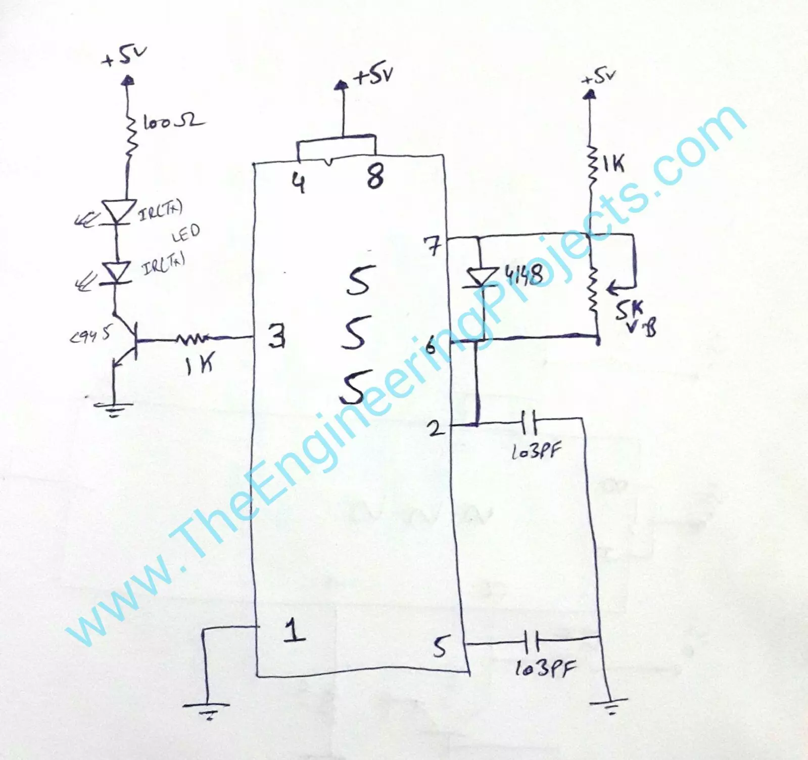
- In the above circuit diagram of IR sensor, I have clearly mentioned all the values of components so that you can easily design it. Moreover there are two leds used in it, these are not simple leds. There are IR leds which emits IR rays. the range of this sensor will depend roughly on the number of leds you are gonna use here, as I used two leds.
- So, now lets have a look at circuit diagram of receiver side.
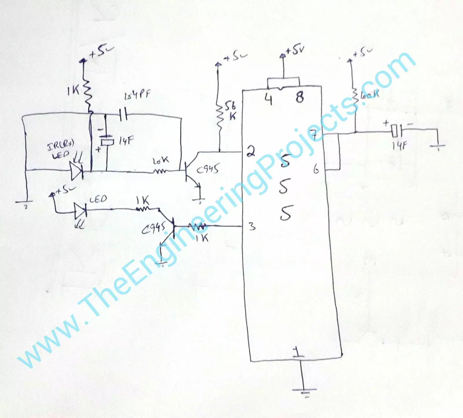
- On this side we have use IR led but that one is receiving and will received that IR rays coming from the transmitter IR leds.
- These are quite simple in designing and you can design it without any trouble. Before going into PCB, its better if you first design them on some wero board or bread board.
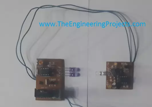
- Here's a manufactured piece of the above given circuit diagrams. The one with two leds is the transmitter and the other one is receiver.
- The image is a bit blur, coz I was in a bit of hurry but they work perfectly fine. :)
- That's all for today, will see you guys in the next tutorial. Till then take care!!!


