555 Timer TV Remote Control Jammer in Proteus


- Introduction to 555 Timer TV Remote Control Jammer.
- Components of the circuit.
- Working principle of 555 Timer Jammer.
- Simulation of the Jammer of TV Remote Control using 555 Timer.
Moreover, you will also learn some interesting facts about the topic in DID YOU KNOW sections. let's jump to our first topic.
555 Timer TV Remote Control Jammer
Remote controls do not require any introduction. We all use many types of remote controller devices in our daily lives. The TV Remote controls work on the principle of Infrared light. Yet, what if we do not want to give any access to other users or there is a requirement of blocking the signals from the remote controller device. In this case, jammers are useful because they do not alter any functioning of remote controls and just distract the television to sense the light signals. On this basis, we define the 555 Timer TV Remote Control Jammer as:
- The 555 Timer TV Remote Jammer is a device used to jam the Infrared Lights emitted by the remote control, by producing a constant pulse of signals and distract the remote controller signals.
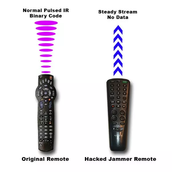
Before starting the working of the TV Remote control Jammer, let's have a piece of quick information on how does the TV Remote works. When we press the button of the remote, it sequentially emits the pulses. These pulses are then received by the IR Reciever present in the Television. Each time, every button has its own frequency of pulses so that the IR Reciever can sense which button is pressed. Then the TV act according to our command.

Now, in the case, when we want to cease the television to sense these signals, we just create a pulse, more powerful than TV remote controller, to disturb the pulse from the TV remote controller, so that the TV will not be able to sense pulses from TV Remote. We'll find how does this works in a bit.
DID YOU KNOW?- In electronics, the Jammer is any device that is used to prevent the instruments to sense the signals, waves or other mediums to cease their response.
Components used in TV Remote Jammer
In our circuit, we are going to use different components such as diodes, resistors, capacitors, etc. Out of them, 555 Timers and transistors are important to understand.
555 Timer in TV Remote control Jammer
The 555 Timer is an excellent Integrated circuit used in thousands of electronic circuits. It is used to transmit the pulses and control the flow of the circuit. The main reason behind its large number of projects and circuits is its modes. Basically, the 555 Timer can be used in three modes:
- Astable Mode
- Bistable Mode
- Monostable Mode
For our circuit, we'll go for Astable Multivariable mode. This mode is chosen so because the IR waves from the remote control have very specific wave frequencies. In this way, when the waves from TV control Jammer will be Astable, this will be better to distract the TV from the remote's pulses. The 555 Timers is an 8 pin IC. In our circuit, pin 5 and pin 7 of the 555 Timer will remain unconnected. Other pins will be connected according to their respected functions.
Transistor in Remote Control Jammer
It's an NPN Transistor with three terminals called Emitter, Collector, and Base Terminals. In our experiment, the BC547 transistor will be used. The transistor will act as an amplifier in the circuit to make the pulses generated by the 555 Timer more clear, strong, and effective.
Complete List of Components required
- 555 Timer IC
- Resistor
- Diode
- Capacitor
- POT HG
- LED
- Battery
- BC547
- Ground Terminal
Working of TV Remote Control Jammer using 555 Timer
- The working of the circuit starts when the 9V Battery starts its work.
- This power enters 555 Timer through its two pins. The 555 Timer, in our case, is in Astable mode.
- In this way, the 555 timer generates a pulse that is not stable.
- To make the pulses more strong and effective, we use the Transistor. The transistor here works as an amplifier and amplifies the pulses coming towards it through its base terminal.
- The output of 555 Timer IC then passes through a couple of Diodes that are connected to the base and Emitter terminal of the BC547.
- Ultimately, the pulses of the 555 Timer IC pass through the LED and then to the collector Terminal of the Transistor.
- The LED shows the speed of the output pulses.
- This abrupt pulse is enough to distract the Infrared Reciever of the Television.
- So, as a result, we get a strong pulse of 36KHz-38KHz carrier frequency,
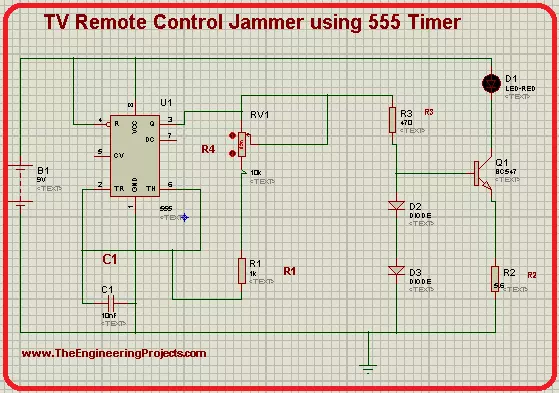
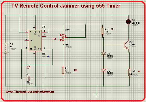
TV Remote Jammer circuit using 555 timers in Proteus
The simulation of the circuit is easy if you follow the steps given below carefully. So Let's go ahead.Procedure to design circuit of TV Remote Jammer
- Excite you Proteus Software and start a new Project.
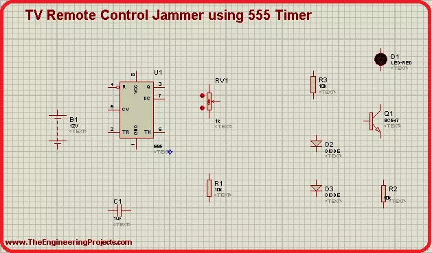
- Hit the "P" button then choose the first 8 components from the window that appeared.
- Now arrange all the chosen components on the screen by following the image given next.
- Go to the left side of the screen>Termnals mode>Ground and attach this ground terminal below the circuit.
- The mode of 555 Timer is identified by the components and their manner of connection with 555 Timer.
- You can change the frequency of the pulses by changing the values of the components.
- This change can easily be detected by observing the speed of the power entering the LED.
- To connect them, let's use connecting wires.
- You can alter the values of some components as:
- Go to virtual instrument Mode>Oscilloscope and fix it with the LED's output.
- Finally, at the present moment, we are going to simulate our circuit.
- Click on the play button and set the values of voltage and frequency through nobs.
- The output of the oscilloscope will show that waves are formed frequently.
In the end, we conclude that we can design the circuit of the TV remote control jammer using the 555 Timer in Proteus. We had a short introduction to how does TV Remote works, we saw how can we jam its signal, we found how does the circuit works and at the end, we design a full circuit of a TV remote control jammer with the help of 555 timers in Proteus ISIS. This circuit emits a constant bit of 1.775 meters per second and the frequency ranges from 36KHz to 38KHz.