TEP , The Engineering Projects , Tutorials

555 Timer

Traffic Signal control in proteus, how traffic signal works, how to design traffic signal control in proteus ISIS
TEP , The Engineering Projects , Boxes

Traffic Signal Control using 555 Timer in Proteus ISIS

TEP , THe Engineering Projects , Shares 2.5K Views
TEP , The ENgineering Projects , Reaction 40
TEP , The ENgineering Projects , Reaction 700
TEP , The ENgineering Projects , Reaction 60
TEP , The ENgineering Projects , Reaction 25
TEP , The ENgineering Projects , Reaction 60
TEP , The Engineering Projects , Pintrest TEP , The Engineering Projects , Pintrest TEP , The Engineering Projects , Pintrest TEP , The Engineering Projects , Pintrest TEP , The Engineering Projects , Pintrest TEP , The Engineering Projects , Pintrest TEP , The Engineering Projects , Pintrest TEP , The Engineering Projects , Pintrest
Shares: 691
TEP , The Engineering Projects , PCBWAY

Traffic Signal control in proteus, how traffic signal works, how to design traffic signal control in proteus ISIS
Hello Friends, i hope you all are fine and enjoying. Now i am going to share my new project tutorial which is Traffic Signal Control using 555 Timer. Up till now i have uploaded a no. of projects using 555 timer and i have got much appreciation from my friends, for some 555 timer based projects like How to use Capacitive Touch Sensor in Proteus ISIS, Sequential LED Blinking using 555 Timer and many more.

Now i am going to share another application of 555 Timer and here we will be using a shift register (4017) next to 555 timer to implement Traffic Signal Control circuit. 4017 is a SERIAL IN PARALLEL OUT shift register. Data enters in a serial manner into register and it leaves the register in parallel manner. 4017 is a 10-bit shift register and it needs a clock pulse to shift data from serial input pin to parallel output pins. Now we need a device which can provide continuous clock pulse to Shift Register. Clock pulse is generated either from Micro-controllers or some sort of timers. Here we will be using 555 Timer to generate clock pulse. It is a very easy project to understand and also very simple to implement. These type of projects are generally designed by the Engineering students in their First or Second semester. Now i am done with the theory of the circuit and now lets move towards the designing of the project.

You can also download the complete simulation of the above described project by simply clicking on the button given below:

Traffic Signal Control using 555 Timer in Proteus ISIS

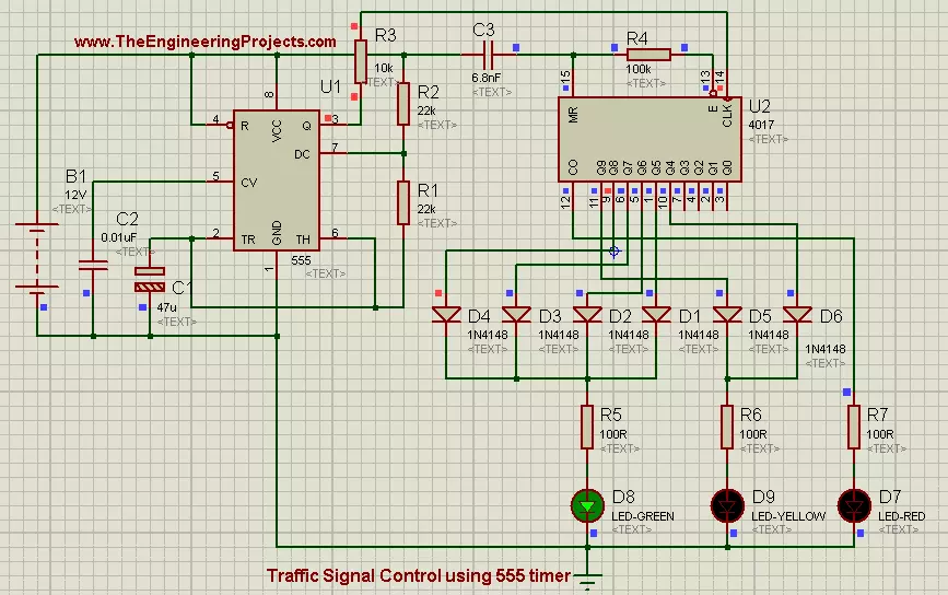
  • First of all place all the components in your proteus workspace,as shown in the image below:
Traffic Signal control in proteus, how traffic signal works, how to design traffic signal control in proteus ISIS
  • Threshold voltage for 555 Timer is 5 volts, and when voltages exceeds this level, 555 timer triggers and it generates a output pulse at its output pin which is ‘Q’ pin.
  • In this project, we will be using a battery of 12 volts as supply voltages.Positive pin (+) of source is connected to Vcc pin of 555 Timer and the Negative pin (-) is connected to GND pin of 555 timer.
  • Pin#3 of 555 timer is connected to CLK pin of shift register and this pin is the data input pin of shift register. Through this pin, 555 timer send data to shift register.
  • At output pins of shift register we have connected 3 Leds, RED, YELLOW and GREEN. Same colors which are used in Traffic Signals.
  • RED led is connected to output pin#12.  YELLOW LED has 2 parallel inputs that are pined at pin#10 and pin#11 respectively. Diodes are connected the way of inputs to block reverse currents. YELLOW led will glow if any of the input will be HIGH.
  • GREEN led has 4 parallel inputs connected at pin# 1,5,6,9 respectively. GREEN led has to blink for longer time, that's why we have connected multiple inputs to it. GREEN led will keep on glowing as along as any of the input will be HIGH.
  • If you connected all the components in their exact position and all the connections are OK, then the final circuit will look like as shown in the image below:
Traffic Signal control in proteus, how traffic signal works, how to design traffic signal control in proteus ISIS
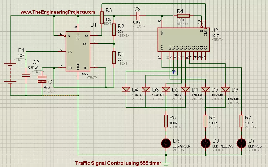
  • Now if you look the above circuit closely then, you will observe that we have connected high valued capacitor (47uf) in the way of trigger pin of 555 timer.
  • The purpose of capacitor is to produce lag in the clock generated by 555 Timer.
  • Now when you will play the simulation then LED will start to glow in periodic manner. First RED led will blink, then YELLOW led will glow and in the end GREEN led will start to glow.
  • All these stages are shown in the image given below:
Traffic Signal control in proteus, how traffic signal works, how to design traffic signal control in proteus ISIS
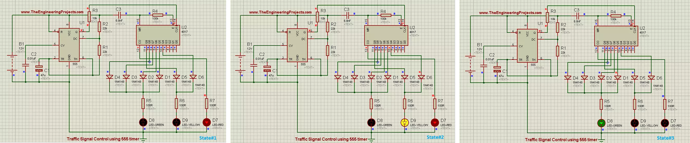
  • As you can see that state#1 represents the "STOP" state, which means that traffic has to stop.
  • State#2 represents "GET READY" state and it means get ready to GO but you are not allowed to go yet.
  • State#3 represents "GO" state, in which traffic is allowed to Go.

Alright friends that was all for today's project. It was a very simple tutorial and most of its portion have been explained in previous tutorials. So i haven't explain it in much detail. But still if you have any problem then, don't feel shy to ask in the comments. Till next tutorial Take Care !!! :)

TEP , The Engineering Projects , TagsTraffic Signal control in proteus
how traffic signal works
how to design traffic signal control in proteus ISIS
TEP , The Engineering Projects , Comments

Write a Comment

TEP , The Engineering Projects , WordPress TEP , The Engineering Projects , Google TEP , The Engineering Projects , Twitter TEP , The Engineering Projects , Facebook TEP , The Engineering Projects , User
TEP , The Engineering Projects , Robot
TEP , The Engineering Projects , Comments Comments on ‘’ Traffic Signal Control using 555 Timer in Proteus ISIS ‘’ (5)
TEP , The Engineering Projects , Comment
TEP , The ENgineering Projects , Reaction 40
TEP , The ENgineering Projects , Reaction 700
TEP , The ENgineering Projects , Reaction 60
TEP , The ENgineering Projects , Reaction 25
TEP , The ENgineering Projects , Reaction 60
this is a nice scheme just too bad that the download link is broken and I would like to have the schedule to try out if it works
TEP , The Engineering Projects , Add

Top PCB Design Service

PCB
TEP, The Engineering Projects, PCB Online
TEP , The Engineering Projects , Add

Embedded Tools

ARDINO
TEP , The Engineering Projects , ARDUINO
TEP , The Engineering Projects , Subscribe

Subscribe Now !!!

Learn Free Pro Tricks

TEP , The Engineering Projects , Mail Receive Quality Tutorials Straight in your Inbox by Submitting your Email ID Below
TEP , The Engineering Projects , Mail
TEP , The Engineering Projects , Books

Engineering Books

TEP , The Engineering Projects , Arduino Programming Book
SALE $20
Text Book for arduino $20
TEP , The Engineering Proects , Star TEP , The Engineering Proects , Star TEP , The Engineering Proects , Star TEP , The Engineering Proects , Star TEP , The Engineering Proects , Star (5.0)
TEP , The Engineering Projects , Arduino Programming Book
SALE $20
Text Book for raspberry pi $20
TEP , The Engineering Proects , Star TEP , The Engineering Proects , Star TEP , The Engineering Proects , Star TEP , The Engineering Proects , Star TEP , The Engineering Proects , Star (3.0)
TEP , The Engineering Projects , Arduino Programming Book
SALE $20
Text Book for arduino $20
TEP , The Engineering Proects , Star TEP , The Engineering Proects , Star TEP , The Engineering Proects , Star TEP , The Engineering Proects , Star TEP , The Engineering Proects , Star (4.7)
TEP , The Engineering Projects , Arduino Programming Book
SALE $20
Text Book for raspberry pi $20
TEP , The Engineering Proects , Star TEP , The Engineering Proects , Star TEP , The Engineering Proects , Star TEP , The Engineering Proects , Star TEP , The Engineering Proects , Star (5.0)
TEP , The Engineering Projects , Category

Categories

TEP , The Engineering Projects , Arduino
TEP , The Engineering Projects , Notification 20K
TEP , The Engineering Projects , Tick 900
TEP , The Engineering Projects , Views 900
TEP , The Engineering Projects , Comments 20K
TEP , The Engineering Projects , Arduino
TEP , The Engineering Projects , Notification 20K
TEP , The Engineering Projects , Tick 900
TEP , The Engineering Projects , Views 900
TEP , The Engineering Projects , Comments 20K
TEP , The Engineering Projects , Arduino
TEP , The Engineering Projects , Notification 20K
TEP , The Engineering Projects , Tick 900
TEP , The Engineering Projects , Views 900
TEP , The Engineering Projects , Comments 20K
TEP , The Engineering Projects , Arduino
TEP , The Engineering Projects , Notification 20K
TEP , The Engineering Projects , Tick 900
TEP , The Engineering Projects , Views 900
TEP , The Engineering Projects , Comments 20K
TEP , The Engineering Projects , Arduino
TEP , The Engineering Projects , Notification 20K
TEP , The Engineering Projects , Tick 900
TEP , The Engineering Projects , Views 900
TEP , The Engineering Projects , Comments 20K
TEP , The Engineering Projects , Arduino
TEP , The Engineering Projects , Notification 20K
TEP , The Engineering Projects , Tick 900
TEP , The Engineering Projects , Views 900
TEP , The Engineering Projects , Comments 20K
TEP , The Engineering Projects , Arduino
TEP , The Engineering Projects , Notification 20K
TEP , The Engineering Projects , Tick 900
TEP , The Engineering Projects , Views 900
TEP , The Engineering Projects , Comments 20K
TEP , The Engineering Projects , Arduino
Matlab
200
TEP , The Engineering Projects , Notification 20K
TEP , The Engineering Projects , Tick 900
TEP , The Engineering Projects , Views 900
TEP , The Engineering Projects , Comments 20K
TEP , The Engineering Projects , Arduino
TEP , The Engineering Projects , Notification 20K
TEP , The Engineering Projects , Tick 900
TEP , The Engineering Projects , Views 900
TEP , The Engineering Projects , Comments 20K