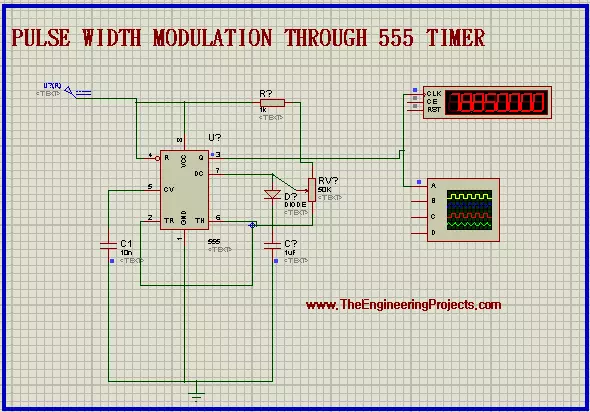
Hello Engineers! Welcome to the board. We hope you are having a good day. In this tutorial, we teach you about Pulse Width Modulation. We'll discuss some important points about the topic. Let's have a look at the Topics of the tutorial: What is Pulse Width Modulation? What is 555 Timer? how does 555 Timer is used in the Pulse Width modulation circuit? How do we design the circuit of Pulse Width Modulation in Proteus ISIS? In addition, you will have some useful information bout Pulse Width Modulator in DID YOU KNOW section. Pulse Width Modulation Pulse width Modulation is a useful technique in the world of Modern Electronics. Let's have a look at the information about Pulse Width Modulation. Abbreviation of Pulse Width Modulation The Abbreviation of the Pulse Width Modulation technique is P ...
Hello Pupils! I welcome you to the board. I hope you are fine. In today's tutorial, we will design a project Metal Detector using 555 Timer in Proteus ISIS. All of us perceive the situations when at the public places such as on airports or in shopping malls where sharp metallic objects such as a knife or illegal guns or even a nail cutter are not allowed, there are walkthrough gates at every entrance so that any person with the forbidden material when passes through the gate, the alarming buzzer automatically switched on. This happened because the walkthrough gates have the Metal Detector circuit in them that works immediately when such a situation occurs. In this session, we'll learn: What are Metal Detectors? How does the 555 Timer collaborate with the circuit of Metal Detector? How does ...
Hey Geeks! Welcome to The Engineering Projects . We hope you are having a reproductive day. We know that sirens are the special sounds that are the symbol that something unusual is occurring or about to occur. You may have experienced the Siren of the Walkthrough Gates at the airport when a person having the knife or other forbidden material pass through it. Or you have heard the Siren of the ambulance and seen that all the traffic gives the way to the ambulance when they hear the special Siren of the Ambulance. The same is the case with the police Siren. The Police sirens are the special sound and it is set with the help of 555 Timer Integrated Circuit. You will learn how can one design a Police siren using the 555 Timer circuit in this tutorial. Let's have a quick list of the topics that ...
Hello friends! This page brings our 555 timer projects together in a practical learning sequence. We will begin with a flashing LED, then move to dimming, counters, servo control and simple sensing circuits. Each linked project contains its own circuit explanation and any available simulation files. The 555 is useful because it lets us study timing without writing a microcontroller program. Resistors, capacitors and the internal switching thresholds determine its behavior. Changing those components and observing the waveforms is an excellent way to connect circuit theory with a visible result. We will also discuss the calculations and limitations that apply across these projects. A circuit that flashes correctly in Proteus still needs sensible component values, suitable output drivers and ...
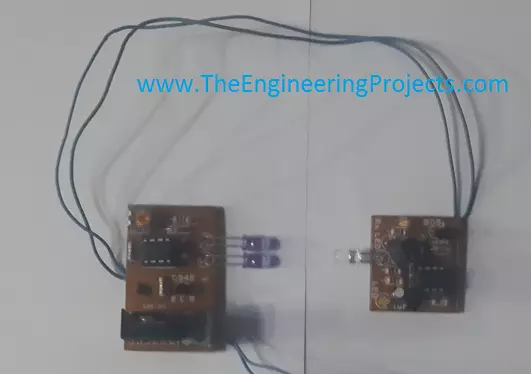
Hello friends! In this tutorial, we will study an infrared sensor built around a 555 timer. We will separate the design into a transmitter that produces infrared light and a receiver that responds when that light reaches it. This is a useful starting point for a beam detector, a simple object detector or an experiment in optical communication. We will also examine the original hand-drawn circuits, explain their timing and current calculations, and identify the details you should resolve before assembling them. A simple infrared detector does not automatically measure distance. Its response depends on the emitter, receiver, alignment, ambient light and the object in the beam. Keeping those limitations clear will make your experiments much easier to interpret. Figure: Original infrared trans ...
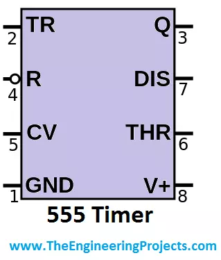
Hello friends! Today, we will answer a basic but very useful question: what is a 555 timer? The 555 is an integrated circuit used to generate delays, pulses and repeating waveforms. By connecting a few external components, we can use the same device as a one-shot timer, an oscillator or a simple two-state control circuit. The important idea is that the 555 watches voltages at its inputs and changes state when they cross defined thresholds. A resistor and capacitor can turn those voltage changes into a time interval. Once you understand that relationship, the familiar timing formulas become much easier to remember and apply correctly. We will examine the internal functional blocks, explain all eight pins, and work through the three common operating modes. We will also distinguish the tradit ...
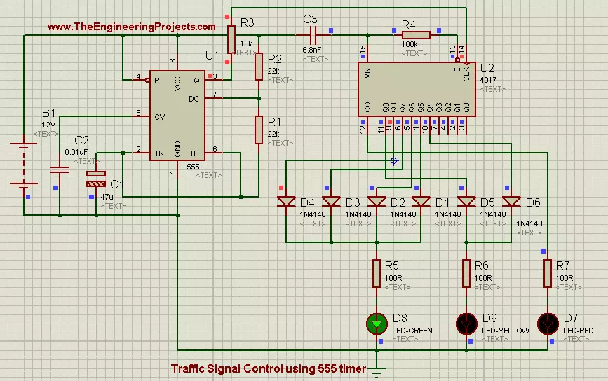
Hello friends! Today, we will build a traffic-signal demonstration using a 555 timer and a CD4017 counter in Proteus ISIS. The timer supplies a repeating clock, the counter advances through ten states, and a few diodes combine those states into red, yellow and green indications. This is a useful introduction to sequencing without a microcontroller. We will keep the original project's teaching flow, but make the timing and output connections more precise. In particular, the CD4017 is a decade counter with decoded outputs, not a serial-data shift register. Its clock input advances a sequence; it does not receive a stream of data bits describing the lamp colors. Our goal is a small educational display. We will calculate the state duration, explain the overlap between red and yellow, and ident ...
Hello friends! Today, we will study relay control using a 555 timer in Proteus ISIS. A relay allows a small control circuit to operate a separate load circuit, and a timer adds a useful extra function: keeping that load on for a selected interval. We will work with a low-voltage DC motor so that the control sequence is easy to observe. Before connecting the components, we need to distinguish manual switching from timed switching. The original project contains a button in the relay-coil path, but that arrangement does not by itself create a timed output. We will first read the original drawing, then develop a monostable circuit whose behavior can be calculated. By the end, you should understand the relay contacts, the transistor interface, the protection diode and the relationship between t ...
Hello friends! Today we will build a single-digit counter using a 555 timer, a CD4026 and a seven-segment display in Proteus ISIS. The timer supplies clock pulses, the counter advances from zero to nine, and its decoder lights the segments needed for each digit. We will also examine three different controls: blanking the display, pausing the count and resetting to zero. They can look similar in a screenshot, but they change different parts of the circuit. Understanding that distinction is useful when you later build event counters or time displays. The original diagrams and download are retained below. We will improve their explanation and add the missing hardware considerations, particularly current-limiting resistors for the display and defined levels on every control input. Figure: Seve ...
Hello friends! Today we will make six LEDs light in a back-and-forth sequence using a 555 timer and a CD4017 decade counter. This extends our multiple LED flasher : instead of switching two whole banks, we will select a different position after each clock pulse. The timer controls how quickly the pattern advances. The counter decides which of ten states is active, and an output-mapping network converts those ten states into a six-position outward-and-return pattern. Separating those jobs makes the circuit easier to understand and troubleshoot. The original screenshots and download remain below. We will correct the description of the 4017 and replace the old output-combining method with diode isolation. Resistors between opposing outputs do not turn those outputs into a proper logic OR func ...