


LM317 Calculator


Hello friends! Today we will work through the LM317 calculator and learn how to choose the resistors for an adjustable power supply. We will start with the basic circuit, calculate an output voltage, and then work backward from a voltage we want to obtain.
The resistor calculation is only one part of the design. A regulator also needs enough input voltage, a suitable load and a way to release the heat it produces. Understanding those conditions will help you avoid a circuit that looks correct in a calculator but gives an unexpected reading on the bench.
If you are new to this device, read our Introduction to LM317 alongside this tutorial. Here, we will concentrate on the calculations and the decisions you can make from them.
Open the LM317 Calculator
Use our LM317 Voltage Regulator Calculator to calculate the output from a resistor pair or find R2 for a target voltage. The tool also provides estimates of input headroom, dissipation and junction temperature. Treat those estimates as design guidance under the selected assumptions, not measurements of your particular regulator.
[LM317TEP]
The pictures retained below show the earlier calculator and circuit examples. Their resistor labels and values belong to those examples; the working convention in this guide is R1 between OUTPUT and ADJUST, with R2 between ADJUST and ground. Follow the connection names whenever another drawing uses different resistor labels.

Understand the Basic Regulator Circuit
The LM317 is an adjustable positive linear regulator. It controls its output so that the voltage between OUTPUT and ADJUST is approximately 1.25 V while operating within its regulation conditions. It does not hold the ADJUST pin at ground.
R1 carries a current set mainly by that reference voltage. R2 converts this current into an additional voltage above ground. Raising R2 raises the ADJUST voltage, and the regulator raises its output to maintain the reference across R1.
| Connection | Purpose | What to check |
|---|---|---|
| INPUT | Receives the unregulated positive supply | Lowest input voltage under load and maximum voltage difference |
| OUTPUT | Feeds the load and R1 | Required voltage, current and thermal dissipation |
| ADJUST | Connects to the junction of R1 and R2 | Resistor ratio and adjustment-pin current |
| Ground | Common return for source, load and R2 | Wiring resistance and voltage drops |
Check the package drawing for the exact part you bought. Do not wire an LM317 by remembering the pin order of a 7805. On common LM317 TO-220 packages, the metal tab is connected to the output, which also matters when mounting multiple devices on a shared heatsink.
LM317 Output Voltage Formula
The usual equation is:
Vout = Vref × (1 + R2 / R1) + Iadj × R2
Here Vref is approximately 1.25 V, resistances are in ohms and Iadj is in amperes. The adjustment current is small, but its contribution becomes more noticeable as R2 increases. Entering 50 rather than 0.000050 for a 50 microamp current would produce a completely incorrect result in a formula expecting amperes.
For a first estimate, ignore the adjustment-current term:
Vout ≈ 1.25 × (1 + R2 / R1)

For example, let R1 be 240 ohms and R2 be 720 ohms. The ratio is three, so the ideal result is 1.25 × 4 = 5 V. With an assumed adjustment current of 50 microamps, the additional voltage is 0.000050 × 720 = 0.036 V. The nominal calculation then gives 5.036 V.
This is a calculated nominal value, not a promise that every assembled circuit will read exactly 5.036 V. Reference tolerance, resistor tolerance, temperature, load conditions and measurement uncertainty still apply. Extra decimal places in the display do not remove those effects.
Calculate R2 for a Required Output
If we know R1 and the desired output, rearrange the approximate equation:
R2 ≈ R1 × (Vout / 1.25 − 1)
Including the adjustment current gives:
R2 = (Vout − Vref) / (Vref / R1 + Iadj)
For a nominal 5 V target with R1 = 120 ohms and Iadj = 50 microamps, this becomes 3.75 / (1.25 / 120 + 0.000050), or approximately 358.3 ohms. A readily available 360-ohm resistor gives approximately 5.018 V under the same assumptions.
The best resistor is not necessarily the value with the most digits. Choose a practical series value, calculate the resulting voltage, and compare the expected variation with the needs of the load. If the load requires tighter accuracy, include the regulator reference tolerance in your decision rather than selecting precision resistors alone.
A Small Table of Nominal Values
The following examples use R1 = 120 ohms and ignore Iadj so you can check the arithmetic quickly. They are calculation targets rather than a complete parts list.
| Target output | Calculated R2 | Ideal divider current through R1 |
|---|---|---|
| 1.8 V | 52.8 ohms | 10.42 mA |
| 3.3 V | 196.8 ohms | 10.42 mA |
| 5 V | 360 ohms | 10.42 mA |
| 9 V | 744 ohms | 10.42 mA |
| 12 V | 1032 ohms | 10.42 mA |

The historical resistor table above is another illustration of the same relationship. Recalculate any selected pair using the actual resistor positions and the assumptions you intend to use. A convenient combination is only suitable when its voltage, load and dissipation requirements are also acceptable.
Why the Minimum Load Matters
The earlier circuit used R1 = 510 ohms. That produces approximately 1.25 / 510 = 2.45 mA through R1. It demonstrates the ratio calculation, but this divider alone does not meet every LM317 minimum-load specification.
The Texas Instruments LM317 datasheet specifies minimum load under stated conditions, including a 10 mA maximum requirement at a 40 V input-to-output difference. A typical value is not a worst-case guarantee. Read the electrical table for the manufacturer, variant and operating conditions you are actually using.
With R1 = 240 ohms, the nominal divider current is about 5.21 mA. With 120 ohms, it is about 10.42 mA. The latter illustrates how the divider can supply a larger standing load, although a rigorous design must still consider reference and resistor tolerances.
The calculator's minimum-load indicator uses a simplified typical threshold. A favorable indication does not establish compliance with a worst-case datasheet limit. Include the external load only if you can guarantee that it remains connected and draws the required current, including startup, sleep and disconnected-load conditions.
For example, an attached circuit drawing 20 mA during operation may draw almost nothing when disabled. A design that regulates only while that circuit is awake can produce a different output when it sleeps. This is why a minimum-load check belongs in the design, not just in the initial measurement.
Check Resistor Power and Tolerance
The voltage across R1 is approximately the reference voltage, so its power is Vref squared divided by R1. At 120 ohms, that is 1.25 squared / 120 = 0.013 W. The lower resistor can dissipate more because its voltage rises with the selected output.
For an approximately 12 V output with R2 = 1032 ohms, the voltage across R2 is about 10.75 V. Its power is approximately 10.75 squared / 1032 = 0.112 W. A resistor rating should include margin and the manufacturer's temperature derating, rather than merely exceed the result by a tiny amount.
Resistor tolerance changes the ratio. With nominal 120 and 360 ohms, independent 1% tolerances give an ideal high-output case of 1.25 × (1 + 363.6 / 118.8), or about 5.076 V. The opposite extremes give about 4.926 V. These figures exclude reference error and adjustment current, so they are not the complete output limits.
A trimmer lets you adjust one assembled unit at one operating condition. It does not eliminate drift or replace adequate thermal design. If a wiper failure could raise the output, arrange the fixed resistance and wiper connection to limit the resulting range, then analyze the open-circuit fault rather than assuming the potentiometer is fail-safe.
Input Voltage and Dropout Headroom
A standard LM317 cannot produce a regulated 12 V output from a 12 V input. The pass element needs voltage across it. The calculator uses a 3 V headroom assumption; actual dropout behavior depends on current, temperature and the chosen device.
For a 5 V design, a first check with that assumption is an input of at least 8 V at the regulator during the lowest part of the supply waveform. Checking only an unloaded adapter label is insufficient. Cable resistance, source regulation and rectifier ripple can reduce the voltage actually available under load.
Suppose an input varies between 7.5 and 9 V. Its average may look comfortable, but the 7.5 V trough is below the calculator's 8 V target. The output can develop ripple or droop during those troughs. Increasing a resistor does not correct a shortage of input headroom.
Conversely, raising the input far above the requirement wastes power as heat. Select the input with both the lowest-voltage regulation condition and highest-voltage thermal condition in mind. Also respect the device's maximum input-to-output differential during startup and output faults.
Estimate Heat Before Choosing a Heatsink
A useful first approximation is P = (Vin − Vout) × Iout. Include current delivered to the programming divider as well as the external load when improving the estimate.
For 12 V input, 5 V output and a 500 mA external load, the load-related loss is 7 × 0.5 = 3.5 W. Adding roughly 10.4 mA of divider current raises this to about 3.57 W. That is a substantial amount of heat for a small package.
For an illustrative thermal resistance of 50 degrees Celsius per watt, the estimated junction rise would be 3.57 × 50 = 178.5 degrees Celsius. At a 25-degree ambient, the simple steady-state estimate is already beyond an acceptable operating condition. Do not interpret the device's nominal current rating as permission to dissipate this power without cooling.
Work backward from a chosen junction target. If the ambient is 40 degrees Celsius and you want to stay below 100 degrees, the permitted total thermal resistance for 3.57 W is (100 − 40) / 3.57 = 16.8 degrees Celsius per watt. This total includes the junction-to-case path, mounting interface and heatsink-to-air path.
Calculator cooling presets are illustrative. The actual result depends on package, copper area, enclosure, airflow and mounting. Internal thermal shutdown is a protective response, not a normal operating mode to use as a thermostat for an undersized heatsink.
Capacitors, Wiring and Practical Assembly
Follow the selected datasheet's application guidance for input bypassing, output capacitance and optional ADJUST bypassing. Capacitors serve different purposes; a large electrolytic far from the regulator does not provide the same local high-frequency path as a nearby bypass capacitor.
Large stored charge can create reverse-current paths when the input is shorted or removed. Where the datasheet calls for protection diodes, select and orient them for those conditions. Do not add a diode from memory without checking which capacitor discharges through which path.
Keep the programming network close to the regulator. Connect the lower end of R2 to a sensible ground reference, avoiding a long shared return carrying heavy load current. A 0.1-ohm return carrying 1 A develops 0.1 V, enough to matter in a supposedly accurate low-voltage supply.
Use the Calculator in a Repeatable Order
- Enter the input voltage expected at the regulator under load.
- Choose R1 with the minimum-load requirement in mind.
- Enter a target voltage to calculate R2, or enter both resistors to inspect their output.
- Review the adjustment-current assumption and available standard resistor values.
- Enter the external load, ambient temperature and a realistic cooling estimate.
- Check headroom, power and temperature before accepting the design.
- Repeat at the lowest input voltage, highest input voltage and relevant load extremes.
Keep a short record of the assumptions with your schematic. “5 V supply” is incomplete; “5 V nominal at 0 to 500 mA, specified input range, chosen minimum load and thermal arrangement” provides something you can actually check.
Simulation and Bench Checks
Our LM317 Voltage Regulator in Proteus tutorial provides the related simulation example. Use it to explore resistor ratios and input changes, while remembering that a model's thermal and fault behavior may differ from a physical assembly.
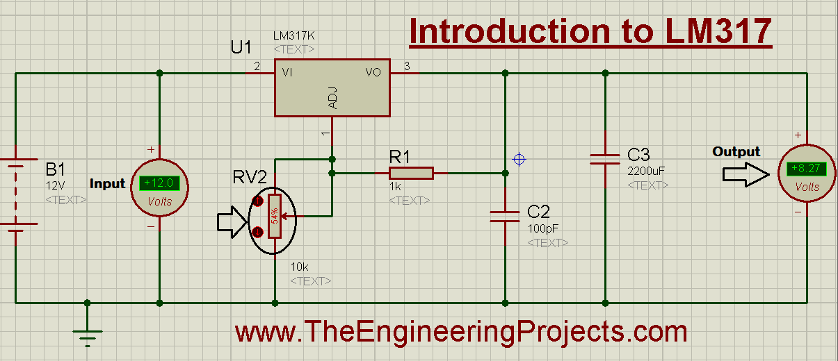
On the bench, first check pin orientation and resistor values with power disconnected. Use a suitably limited low-voltage supply, measure the output before connecting the intended load, and then increase the load while monitoring input voltage, output voltage and temperature. The calculations here are worked examples; they are not a new hardware test report.
| Observation | Possible explanation | Next check |
|---|---|---|
| Output below target | Insufficient headroom or excessive load | Measure input at the device under load |
| Output rises with load disconnected | Minimum load not maintained | Check divider and guaranteed standing load |
| Output drifts or cycles after warming | Thermal limitation | Calculate dissipation and inspect cooling |
| Output differs by a small percentage | Reference and resistor tolerances | Compare measured resistances and error budget |
| Unexpectedly high output | Incorrect pinout or open adjustment path | Disconnect the load and inspect the circuit |
Calculator Review and FAQs
What does this calculator do well?
It connects the resistor ratio to output voltage and makes the cost of extra input voltage visible through power and temperature estimates. Its limits are the assumed device values and cooling model, which you must replace with suitable design data when necessary.
Can an ordinary LM317 circuit produce zero volts?
Not with the basic ground-referenced two-resistor arrangement. Its minimum setpoint is approximately the reference voltage. A zero-volt output requires a different arrangement, such as a suitable negative reference or another regulator architecture.
Can I obtain more output voltage than the input?
No. This is a linear step-down regulator. A resistor calculation above the available input does not create a boost converter.
Should I always use 240 ohms for R1?
No. It is a common example value, but minimum load and operating conditions decide whether it is suitable. Check the complete load path and the exact part's specifications.
When should I consider a switching regulator?
Consider one when the voltage drop and current produce unacceptable heat or battery loss. Compare noise, complexity and efficiency with the actual requirements rather than assuming either regulator type is best for every circuit.


Comments
1