Welcome to the next tutorial of our raspberry pi 4 programming course. The last guide covered connecting a Sharp infrared distance measurement sensor to a Raspberry Pi 4. Infrared (IR) sensors were demonstrated to be widely used for nearby object recognition and motion tracking. But in this session, we'll utilize Raspberry Pi 4 to create a radio-frequency (RF) remote control that can be used to operate the gadgets wirelessly. With the help of this RF remote control, we can Power On/Off the devices.
Transmitter Side
RF Transmitter
HT12E IC
4 Push Buttons
750k resistor
9 Volt battery
Receiver Side
Raspberry Pi
16x2 LCD
10K POT
Breadboard
1K Resistor (Five)
33K resistor
HT12D IC
RF Receiver
LEDs (Five)
4 10K resistor
Jumper wires
This ASK Hybrid Transmitter/Receiver module communicates at 433Mhz. For optimal range and frequency stability, this module utilizes a crystal-stabilized oscillator. The module requires only a single external antenna.
This module is for you if you need RF communication over a great distance at a low cost. The high levels of background noise at this frequency and in its Analog technology mean that this module cannot directly transmit data via the UART communication of a PC or microcontroller. Using encoder and decoder ICs, we may utilize this module to retrieve information from background static.
At full Power, a transmitter's range is over 100 meters; at 5 volts, it's around 50-60 meters when employing a single-code wire antenna measuring just 17 centimetres.
There are two primary limitations placed on the wireless system designer: the system must function within a particular range and send a certain quantity of data within a given data rate. The RF module is incredibly compact and can run on a broad voltage spectrum (from 3V to 12V).
Transmitter and receiver RF modules operating at 433 MHz constitute the bulk of the RF modules. Because the carrier frequency is completely suppressed during transmission of logic zero, the transmitter's power consumption is significantly reduced during battery operation. A logic one signal turns the carrier on to around 4.5mA at 3 volts when it is off at 0 volts. The data is transmitted serially from the transmitter to the tuned receiver. Two microcontrollers are suitably interfaced with the transmitter and receiver for communication.
Range of Operation: 433 MHz
Power at the Output: 4-16 dBm
Power supply input: 3 to 12-volt dc
GND stands for "ground," which indicates a supply connection to the earth.
Data in - When serial data is received from an encoder, it is input via this pin.
VCC - This jack must be wired to Vcc - +5 Volt.
Antenna - The data transmission antenna wraps around this pin.
The sensitivity is -105 dBm.
IF Rate of 1 megahertz.
Less need for a power supply.
The current is 3.5 mA.
Five-volt power source.
GND - Ground
Data In - This pin give
s output serial data to Decoder
Vcc - +5 Volt should be connected to this pin
GND - Ground
GND - Ground
Antenna - A wrapped connection to this pin for proper Reception of data
The output pin on an HT12E is used for its principal purpose, which is to transmit a 12-bit encoded signal. The IC's built-in Oscillator makes it simple to put it to use. The IC may operate from 2.4V – 12V, although in most cases, +5V is supplied to the Vcc (pin 18), while pin 9 is left unconnected. Connect pin 14 (Transmission Enable) to the ground terminal to start the transmission process. This IC has an integrated oscillator, which is necessary for data decoding. To activate it, we need only connect pins 15 and 16 (OSC1 and OSC2) with a 1M resistor. The address, which is 8 bits long, must be established using pins A0–A7, and the data to be transmitted, which is 4 bits long, must be given to pins AD0–AD1. Your Decoder must have the same address for the two devices to communicate. Below is a simple HT12E IC wiring diagram.
Through the use of a series of ground connections on the address pins, I have programmed the eight-bit address data in the circuit above to read 0b00000000. Any eight pins can be made high by connecting it to 5V to improve security. A +5V supply, such as that provided by a voltage regulator such as 7805, is used to power the entire IC. Any Digital IC capable of supplying the required 4-bit data will do, and its pins AD3, AD2, AD1, and AD0 will be linked to those. They can be connected to switches for manual data transmission and Reception. In this example, I have set all four data bits to be zero (low), and the HT12D decoder IC's output will be the same type of bits. Similarly, if we modify these four bits, the HT12D's output will change accordingly.
The Dout pin is where you'll find the encoded 12-bit value (pin 17). The HT12D has to receive this information to decode it, and it can do so via wire or a wireless channel (such as RF or IR). Following this, you will know the necessary to configure the HT12D.
HT12D's main job is to interpret the 12-bit signal through the input pin. The IC's built-in Oscillator makes it simple to put it to use. The IC's ground (pin 9) and power (pin 18) terminals should be connected to 5V. This IC has an integrated oscillator, which is necessary for data decoding. It's activated by connecting pins 15 and 16 (OSC1 and OSC2) using a 470K resistor. Received data in increments of 4 bits are available on pins AD0 and AD1, and an address in increments of 8 bits must be programmed using pins A0 through A7. The Decoder's address must match the encoder's if you want to use it successfully. See below for a simplified circuit depiction of the HT12D IC.
Through the use of a series of ground connections on the address pins, I have programmed the eight-bit address data in the circuit above to read 0b00000000. Any eight pins can be made high by connecting it to 5V to improve security. A +5V supply, such as that provided by a voltage regulator such as 7805, is used to power the entire IC. Any Digital IC capable of reading 4-bit data will work with the AD3, AD2, AD1, and AD0 pins. As a bonus, they can be hooked up to an LED so you can see the data being transmitted in real-time. Due to the uncertainty of the Encoder IC's Input signal, the four-bit output data is represented as a question mark. If there is any good information received, it can be read off of these four pins.
The HT12E Encoder IC's description is provided to help you learn how to encode a 4-bit data stream for transmission to the IC's input pin.
In this setup, four buttons on the transmitter side (the remote) activate corresponding LEDs on the receiver side. Whenever one of the four buttons is pressed, a signal is sent to an encoder IC, which then passes it on to a radio frequency (RF) transmitter, which broadcasts it into the surrounding environment. The RF receiver picks up the signal, which then transmits the 4-bit decoded signal to the Raspberry Pi through the Decoder IC HT12D. The Raspberry Pi will then interpret these data snippets, perform the appropriate action, and activate the corresponding LED. Once a key is pressed, a buzzer will sound for one second. In addition, a 16x2 LCD shows whether the LEDs are on or off.
For the demonstration, this project only uses four LEDs; to initiate any action, press the appropriate button on the "RF Remote." The LEDs may be swapped out for AC home appliances via the relay, and the same "RF Remote" can be used to operate both sets of lights wirelessly. Consequently, you may use the same circuit for your RF-based Raspberry Pi-based home automation project. You can see all of the Home Automation Projects we've produced in the past, including Bluetooth, DTMF, GSM control, and more, right here: Home Automation Projects.
This RF remote control for the Raspberry Pi features an easy-to-assemble circuit consisting of just the Pi board, a few buttons, an LCD, an RF pair, and an encoder/decoder IC. Raspberry Pi manages the LCD, processes input, and communicates results. However, any Raspberry Pi model should do in this case; Raspberry Pi 3 was utilized. The circuit consists of an RF receiver section and an RF transmitter section. The below figure depicts both circuits.
LCD pins rs, en, d4, d5, d6, and d7 from the receiver are wired to GPIO pins 11, 10, 6, 5, 4, 1, and 4 in 4-bit Mode. The RF receiver picks up the signal and decodes it by the HT12D IC once it has been sent from the RF transmitter. Decoder IC pins D8, D9, D10, and D11 of the HT12D are linked straight to wiringPI GPIO pins 25, 24, 23, and 22. LEDs are wired to wiringPi GPIO pins 26, 27, 28, and 29 for output. When a key is pressed, the buzzer connected to wiringPi GPIO 0 sounds an alarm.
The HT12E Encoder IC is part of the RF transmitter circuit, with four buttons used to toggle the LEDs on and off. Every address line in an encoder/decoder IC is grounded.
To access the Raspberry Pi's GPIO pins in C, we must use the wiringPi Library, much like how Python programmers include the import RPi.GPIO as an IO header file. You can use Terminal or an SSH client like Putty to execute the commands below one by one to complete the installation. If you want more information on how to work with and set up the Raspberry Pi, read our introduction to Raspberry Pi tutorial.
sudo apt-get install git-core
sudo apt-get update
sudo apt-get upgrade
git clone git://git.drogon.net/wiringPi
cd wiringPi
git pull origin
cd wiringPi
./build
Test the installation of wiringPi Library by using the below commands:
gpio -v
gpio readall
We start by including the necessary header files and defining the LCD's pins, and then we initialize certain variables and connection pins for receiving input and displaying LED indications.
#include "wiringpi.h"
#include "wiringserial.h"
#include "stdio.h"
#include "string.h"
#define RS 11
#define EN 10
#define D4 6
#define D5 5
#define D6 4
#define D7 1
#define led1 26
#define led2 27
#define led3 28
#define led4 29
#define buzz 0
#define d1 25
#define d2 24
#define d3 23
#define d4 22
int am = 0;
int flag1=am ,flag2=am ,flag3=am ,flag4=am;
Then, in the void setup() procedures, we tell all the GPIO Pins what to do.
void setup()
{
if (wiringPiSetup () == -1)
{
clear();
print("Unable to start");
setCursor(0,1);
print("wiringPi");
}
pinMode(led1, OUTPUT);
pinMode(led2, OUTPUT);
pinMode(led3, OUTPUT);
pinMode(led4, OUTPUT);
We have used the digitalRead and digitalWrite functions in the code to receive and send the Decoder's output to an LED and a device, respectively.
while(1)
{
setCursor(0,0);
print("D1 D2 D3 D4");
if(digitalRead(d1)==0)
{
flag1++;
setCursor(0,1);
if(flag1%2==1)
{
print("ON ");
digitalWrite(led1,HIGH);
}
Additional functions utilized in this project are listed below. To send a command to the LCD, use the void lcdcmd method, and to provide data to the LCD, use the void write function. You can call the void clear() function to reset the LCD. The cursor is used to deliver a string to the LCD instead of printing it. To start the LCD up in 4-bit Mode, call the void to begin, and use the void buzzer() function to make the buzzer sound. Find the complete code for this RF remote control using a Raspberry Pi below.
#include "wiringpi.h"
#include "wiringserial.h"
#include "stdio.h"
#include "string.h"
#define RS 11
#define EN 10
#define D4 6
#define D5 5
#define D6 4
#define D7 1
#define led1 26
#define led2 27
#define led3 28
#define led4 29
#define buzz 0
#define d1 25
#define d2 24
#define d3 23
#define d4 22
int am = 0;
int flag1=am ,flag2=am ,flag3=am ,flag4=am;
void lcdcmd(unsigned int ch)
{
int temp=0x80;
digitalWrite(D4, temp & ch<<3);
digitalWrite(D5, temp & ch<<2);
digitalWrite(D6, temp & ch<<1);
digitalWrite(D7, temp & ch);
digitalWrite(RS, LOW);
digitalWrite(EN, HIGH);
delay(10);
digitalWrite(EN, LOW);
digitalWrite(D4, temp & ch<<7);
digitalWrite(D5, temp & ch<<6);
digitalWrite(D6, temp & ch<<5);
digitalWrite(D7, temp & ch<<4);
digitalWrite(RS, LOW);
digitalWrite(EN, HIGH);
delay(10);
digitalWrite(EN, LOW);
}
void write(unsigned int ch)
{
int temp=0x80;
digitalWrite(D4, temp & ch<<3);
digitalWrite(D5, temp & ch<<2);
digitalWrite(D6, temp & ch<<1);
digitalWrite(D7, temp & ch);
digitalWrite(RS, HIGH);
digitalWrite(EN, HIGH);
delay(10);
digitalWrite(EN, LOW);
digitalWrite(D4, temp & ch<<7);
digitalWrite(D5, temp & ch<<6);
digitalWrite(D6, temp & ch<<5);
digitalWrite(D7, temp & ch<<4);
digitalWrite(RS, HIGH);
digitalWrite(EN, HIGH);
delay(10);
digitalWrite(EN, LOW);
}
void clear()
{
lcdcmd(0x01);
}
void setCursor(int x, int y)
{
int set=0;
if(y==0)
set=128+x;
if(y==1)
set=192+x;
lcdcmd(set);
}
void print(char *str)
{
while(*str)
{
write(*str);
str++;
}
}
void begin(int x, int y)
{
lcdcmd(0x02);
lcdcmd(0x28);
lcdcmd(0x06);
lcdcmd(0x0e);
lcdcmd(0x01);
}
void buzzer()
{
digitalWrite(buzz, HIGH);
delay(1000);
digitalWrite(buzz, LOW);
}
void setup()
{
if (wiringPiSetup () == -1)
{
clear();
print("Unable to start");
setCursor(0,1);
print("wiringPi");
}
pinMode(led1, OUTPUT);
pinMode(led2, OUTPUT);
pinMode(led3, OUTPUT);
pinMode(led4, OUTPUT);
pinMode(buzz, OUTPUT);
pinMode(RS, OUTPUT);
pinMode(EN, OUTPUT);
pinMode(D4, OUTPUT);
pinMode(D5, OUTPUT);
pinMode(D6, OUTPUT);
pinMode(D7, OUTPUT);
pinMode(d1, INPUT);
pinMode(d2, INPUT);
pinMode(d3, INPUT);
pinMode(d4, INPUT);
digitalWrite(led1, LOW);
digitalWrite(led2, LOW);
digitalWrite(led3, LOW);
digitalWrite(led4, LOW);
digitalWrite(buzz, LOW);
begin(16,2);
}
//void loop()
void main()
{
setup();
clear();
print(" RF Module ");
setCursor(0,1);
print(" Interfacing ");
delay(2000);
clear();
print("Raspberry Pi");
setCursor(0,1);
print("Circuit Digest");
delay(2000);
clear();
print("System Ready");
delay(1000);
clear();
setCursor(0,1);
print("OFF OFF OFF OFF");
while(1)
{
setCursor(0,0);
print("D1 D2 D3 D4");
if(digitalRead(d1)==0)
{
flag1++;
setCursor(0,1);
if(flag1%2==1)
{
print("ON ");
digitalWrite(led1,HIGH);
}
else
{
print("OFF");
digitalWrite(led1,LOW);
}
buzzer();
while(digitalRead(d1)==0);
}
else if(digitalRead(d2)==0)
{
flag2++;
setCursor(4,1);
if(flag2%2==1)
{
print("ON ");
digitalWrite(led2,HIGH);
}
else
{
print("OFF");
digitalWrite(led2,LOW);
}
buzzer();
while(digitalRead(d2)==0);
}
else if(digitalRead(d3)==0)
{
flag3++;
setCursor(8,1);
if(flag3%2==1)
{
print("ON ");
digitalWrite(led3,HIGH);
}
else
{
print("OFF");
digitalWrite(led3,LOW);
}
buzzer();
while(digitalRead(d3)==0);
}
else if(digitalRead(d4)==0)
{
flag4++;
setCursor(12,1);
if(flag4%2==1)
{
print("ON ");
digitalWrite(led4,HIGH);
}
else
{
print("OFF");
digitalWrite(led4,LOW);
}
buzzer();
while(digitalRead(d4)==0);
}
}
}
Transmitted modules, which plug into the Raspberry Pi, allow for the transmission of radio frequency signals at a range of 433 MHz to remote receivers. Devices like remote controllers, headphones, baby phones, and additional Raspberry Pis can pick up these signals. An RF module's performance will vary from that of other radio-frequency devices depending on several parameters, such as the strength of the transmitter, which directly affects the range of the signal it can collect. The downside is that this will significantly reduce the battery life of the transmitter device. Using this device with a higher transmission power will also cause interference with nearby RF appliances. The subsequent tutorial will cover the Bluetooth connection between a Raspberry Pi 4 and an ESP32.
Hello friends, I hope all are fine. Today, we are going to share the 3rd chapter of Section-III in our Raspberry Pi Programming Course. In our previous lecture, we interfaced the Soil Moisture Sensor with Raspberry Pi 4. Today, we are going to Interface the Infrared(IR) sensor with RPi4.
IR Sensor is typically employed for the presence/motion detection of objects in the immediate area. With their low power consumption, straightforward design, and user-friendly features, IR sensors are a popular choice for detection purposes. Infrared(IR) impulses are invisible to the naked eye and lie between the visible and microwave parts of the electromagnetic spectrum. So let's get started:
To learn how an IR sensor detects the existence of an object, we'll set up a basic circuit to detect any object. The following electronic components are required for this task:
An infrared sensor incorporates an infrared LED(light-emitting diode) and a photodiode, which, when joined together, can function as a photo-coupler or optocoupler. This sensor employs Plank's radiation, Stephan Boltzmann, and Wein's displacement principles of physics.
The infrared LED is a transmitter that produces IR radiations. Visually, the IR LED is identical to a regular LED, although the IR radiation is invisible to the naked eye. Radiation sent out by an infrared source is primarily detected by an infrared receiver. Photodiodes are one physical shape that these infrared detectors can take. Unlike regular photodiodes, IR photodiodes only respond to infrared light. Variations in voltage, wavelength, package size, etc., are the primary categories separating the many types of infrared receivers.
The wavelength of the IR receiver must be the same as that of the IR transmitter whenever the two are utilized together. In this case, an infrared LED acts as the sender, and an infrared photodiode acts as the receiver. An infrared LED produces infrared light, which an infrared photodiode can detect. The amount of IR light collected correlates with the photo-resistance diodes and the resulting shift in output voltage. It is on this concept that the IR detector operates.
Some of the infrared radiation sent out by the transmitter will be reflected back to the receiver. The IR receiver can calibrate the sensor output to the level of the response.
You can choose between active or passive IR sensors when shopping for an infrared detector.
Active IR Sensor
The active infrared sensor, we are going to use in today's project, incorporates both the transmitter and the receiver.
These detectors can receive and process data via radiation from an external source. The signal processor can then be used to extract the data that is required for further analysis. The reflectance sensor and the break beam sensor are the two most common active infrared sensors.
Passive IR Sensor
Passive infrared sensors consist solely of detectors and lack any transmitter. A transmitter or infrared source is used in these sensors. An infrared detector can pick up the object's radiation. The signal is then processed by a signal-understanding device to extract the necessary data.
The pyroelectric detector, the bolometer, the thermocouple-thermopile, etc., are all excellent examples of this type of sensor. Thermal infrared sensors and quantum infrared sensors are two examples of these devices. The wavelength is not a factor for the thermal IR detector. For these sensors to function, they use a hot energy source. Infrared quantum sensors have a fast response and detection times; their sensitivity is wavelength-dependent. To take accurate readings, these sensors must be regularly cooled.
The infrared sensor is one of the most common and fundamental sensor circuits in modern electronics. One of the most prominent uses for this sensor is obstacle detection. The following elements are used in IR circuit:
An infrared (IR) sensor located in the transmitter part constantly broadcasts IR waves that are picked up by an infrared (IR) receiver module. How the receiver receives IR photons affects what comes out of its IR output terminal. Because this deviation cannot be examined separately, it can be sent into a comparator circuit. An LM339 operational amplifier (op-amp) is employed in this application as a comparator.
Without a signal, the comparator IC's inverting input has a greater potential than its non-inverting counterpart (LM339). As a result, the LED doesn't light up and the comparator's output drops low. The input's inverting potential will drop when the IR receiver module detects an incoming signal. As a result, the comparator's (LM 339) output gets high, and the LED lights up.
The IR LED Devices, such as the Photodiode, require a current of at least 10 mA, which is maintained by Resistors R1 (100), R2 (10k), and R3 (330). Output terminal adjustments are made with resistor VR2 (preset=5k). Circuit sensitivity is adjusted by resistor VR1 (preset=10k). Learn more about IR detectors by reading up on the topic.
Below is a schematic of the IR sensor's transistor-based circuit, demonstrating how to use two transistors for obstacle detection. This circuit's primary function is to detect obstacles in the path of an infrared LED. So, two transistors, such as NPN and PNP types, are all you need to use to construct this circuit. Transistors of the BC547 and BC557 types are utilized, respectively, for NPN and PNP operations.
For the above circuit to work, one IR LED must be ON at all times, while the other IR LED is connected to the base terminal of the PNP transistor. Infrared (IR) LEDs-2, 100-ohm, and 200-ohm resistors, BC547 and BC557 transistors, and a simple LED are all needed for this design.
When an infrared LED is identified, a tiny current is distributed through the sensor, thanks to the object's reflected light. By doing so, the NPN and PNP transistors are turned on, and the LED lights up. You may use this circuit to make automatic lamps that turn on when someone walks into the room.
If you want to use the Raspberry Pi's infrared (IR) sensor to identify an object, you'll need to create a Python script; to do so, launch the nano text editor and navigate to the file named "irsensor.py."
nano ir_sensor.py
This is the Python code we will be writing now:
import RPi.GPIO as GPIO
#importing the library of RPi.GPIO
import time
#importing the library of time
sensor = 16
#declaring BCM pin 16, which is GPIO 23 of Raspberry Pi
led = 18
#declaring BCM pin 18, which is GPIO 24 of Raspberry Pi
GPIO.setmode(GPIO.BOARD)
#declaring the BCM mode of pins
GPIO.setup(sensor,GPIO.IN)
#set the behavior of the sensor as input
GPIO.setup(led,GPIO.OUT)
#set the behavior of led as output
try:
while True:
#initiated an infinite while loop
if GPIO.input(sensor):
#checking input on the sensor
GPIO.output(led, False)
#led turned on
while GPIO.input(sensor):
#checking input on the sensor again
time.sleep(0.2)
#generate a time delay of 0.2 seconds
else:
GPIO.output(led,True)
#led turned off if there is no input on the sensor
except KeyboardInterrupt:
# terminate the program
GPIO.cleanup()
#cleanup the GPIO pins for any other program use
Time and the RPi.GPIO library has been imported, and pins 16 and 18 have been designated with the sensor and the LED, respectively. Setmode = GPIO.BOARD; sensor = input; led = output; these PINs correspond to the board's PINs.
Then, when an object is detected, the sensor's input is checked in an infinite while loop to determine whether or not the LED's brightness should increase. Now run the Python file in your terminal, and you should see the led blink when an object is detected.
When the subject is not in range, and the LED is turned off:
The LED will light up as the object passes over the IR sensor.
Infrared (IR) sensors can be broken down into several categories depending on their intended use. Examples of how various sensor technologies are typically put to use. It is possible to get numerous motors working in unison using a speed sensor. The sensor's temperature readings are used in factories for climate regulation. The passive infrared (PIR) sensor is employed in an automated door opening system, whereas the ultrasonic (US) sensor measures distance.
The infrared (IR) sensors detailed below can be found in various sensor-based applications and electrical gadgets.
Radiation Thermometers
Features of radiation thermometers, which use infrared (IR) sensors to determine an object's temperature, vary with the object's material and temperature.
remote sensing and measurement, where no physical contact is required
quicker response
Simple Pattern Sizing
Flame Monitors
The light given off by the flames may be detected, and the fire's progress can be tracked with such gadgets. Flames emit a wide spectrum of light, from ultraviolet to infrared. Numerous types of detectors, including PBS, PbSe, Two-color detectors, and pyroelectric detectors, are utilized in flame monitors.
Gas Analyzers
Gas analyzers use IR sensors to analyze gas based on their absorption characteristics in the IR region. Two techniques are utilized: dispersive and non-dispersive. In the dispersive method, the emitted light is separated spectroscopically, and the absorption is analyzed to determine the gas composition and sample quantity. The non-dispersive method, also known as NDIR technology, is the more widely used technique. It employs optical filters similar to sunglasses to filter out unwanted radiation and determines the absorption without spectroscopically separating the emitted light. NDIR analyzers are commonly used for carbonated drinks, while non-dispersive analyzers are frequently used for automotive exhaust gas analysis and fuel leak detection.
IR Imaging Devices
An IR imaging device generally applies IR waves due to its invisible property. It finds use in thermal cameras, night vision equipment, and others. All objects, including water, rocks, soil, vegetation, the atmosphere, and human tissue, emit IR radiation, which the Thermal infrared sensors measure within the IR spectrum to create a map of the object/area's temperature distribution. Thermal cameras are often made up of Sb (indium antimonite), Gd Hg (mercury-doped germanium), and Hg Cd Te (mercury-cadmium-telluride) sensors.
The IR sensor's transmitter continuously sends out infrared beams, which bounce back when they encounter an object. The receiver of the IR module then detects these beams, resulting in a high output from the IR sensor. IR technology has various applications in daily life and industries, such as televisions, where an IR sensor detects signals from a remote control. In this article, we have integrated the IR module with the Raspberry Pi 4 and demonstrated the functioning of the IR module through a simple object detection project.
So, that was all for today. In the next lecture, we will interface PIR Sensor with Raspberry Pi 4. Till then, take care. Have fun!!!
Thank you for joining us today for our in-depth Raspberry Pi programming tutorial. The previous guide covered the steps necessary to connect a fingerprint scanner to a Raspberry Pi 4. In addition, we developed a python script to complement the sensor's ability to identify fingerprints. Yet, in this guide, we'll discover how to interface a ws2812 RGB to a Raspberry Pi 4.
Bright, colorful lights are the best, and this tutorial shows you how to set up Fully Configurable WS2812B led strips to run on a Pi 4 computer as quickly and flexibly as possible. In that manner, you can have the ambiance of your home reflect your tastes.
In most cases, when people talk about a "WS2812B Strip," they mean a long piece of extensible PCB with a bunch of different RGB LED Nodes spread out and dotting all along the top. As a bonus, WS2812B strips can be addressed individually. Each RGB node can independently set its own color and brightness. The functionality of non-addressable RGB strips will be identical to that of WS2812B strips. WS2812B Strips are superior in every way, allowing for more imaginative LED light shows. It is possible to create more complex animations, stripes, and chases by individually programming the actions of each LED Node.
The "WS" in WS2812B indicates that this is the second major revision of this design; "World Semi" refers to the chip's original equipment manufacturer, "2812" to its specific part number, and "B" to its revision number. Each WS2812B LED Node contains an integrated circuit chip, as shown below.
Fully Configurable Strip LEDs now come in wide varieties. It's important to remember whether the strip operates on 5 volts or 12-volt power. To power our 5V-powered Raspberry Pi Computer, we need to use a 5V power supply. Or we'll have to install extra gear to meet the 12v Dc power specifications. LED Node densities also vary across WS2812B LED strips. Since our strip consists of WS2812B nodes soldered onto rigid PCBs, it may also be controlled by the Python script included in this article. ws2812B LED strips are the ideal LEDs to use because of the benefits above. What this manual entails is listed below.
The control mechanism implemented in this tutorial works with WS2812B LED nodes, whether they are rigidly coupled on a PCB or flexibly arranged over a long strip. No prior experience with Raspberry Pi has required, thanks to our comprehensive online raspberry pi 4 for the introduction. You should be able to follow these guidelines if you've read at least chapter 1.
Where To Buy? | ||||
---|---|---|---|---|
No. | Components | Distributor | Link To Buy | |
1 | Jumper Wires | Amazon | Buy Now | |
2 | Raspberry Pi 4 | Amazon | Buy Now |
Let's go over the protocol for these addressable LEDs so you can see how they function. Each WS2812B unit's red, green, and blue LEDs can be independently controlled to one of 256 brightness levels. Each LED module needs 24 bits of data or three groups of eight brightness bits. Here's a quick rundown of the steps involved:
The first LED in the string receives this data stream from the microcontroller, which consists of eight green bits, eight red bits, and eight blue bits.
In the case of several LEDs, the data sequence for the second LED begins with green, red, and blue information immediately after the information for the first LED. The process repeats itself until each LED is turned on.
The first LED acts as a receiver for data for all subsequent LEDs in the chain and then sends that data to the second LED without applying the same sequence.
When the original "number one" LED unit runs out of binary LED sequences, it passes the baton to the next available unit.
What follows are detailed instructions for configuring a single Raspberry Pi board to manage many individually addressable LEDs.
A pi 4
5v led strip
A DC barrel jack to 2-pin terminal block adapter.
More than 30 WS2812B strip Nodes will necessitate the usage of an external power supply. Even with highly efficient LEDs, producing brilliant light takes a lot of energy. On average, each pixel will consume 20mA, and while projecting white light at full brightness, each pixel will consume 60mA. This information shows us that 30 Pixels can consume 600mA on average and 1.8A at full brightness. As a side note, staring directly into a room with the lights set to full white causes blind spots in my vision. Because of this, I typically set the brightness of my WS2812B lights to 20%. Ensure your WS2812B strip's power source is adequate for the illumination level you intend to achieve.
In today's world, 3.3V data logic is compatible with most WS2812B LED nodes. The GPIO Pins on a Raspberry Pi have an operational voltage range of 0 to 3.3V; therefore, this works out perfectly. This surface-mounted WS2812B strip Node has seen five minor changes since its inception. Since the earlier WS2812B strip can only work on 5V Data Logic, a logical level shifter may be necessary if you're experiencing strange or intermittent issues.
We'll configure our Raspberry PI to look and act like a desktop PC because that's how most people use computers at home and because it's the most user-friendly setup for novice makers. To convert our Raspberry Pi into a desktop computer, we'll need to install a micro-SD card pre-flashed with the operating system. Then hook it up to a monitor via HDMI and a mouse/keyboard combo. Also, this is a good moment to install a small heatsink on the Raspberry Pi Board's central processing unit IC. Look at the image below to see the setup adjacent to a short WS2812B LED strip with three wires protruding from it. The WS2812B has three wires that have not yet been connected to the Raspberry Pi. WS2812B LED Strip PCBs are often marked with arrows to indicate the direction of data flow. It is a common problem in troubleshooting when this is ignored.
How to Configure Hardware for WS2812B Chains with fewer than 30 Nodes We need to plug in the 5V WS2812B Strip's three wires to the Raspberry Pi before turning the power on. Link the Raspberry Pi's 5V Power Input Pin with the Red Power Cable. Join the white wire labeled "Ground" to the Pi's Ground pin. Join the Raspberry Pi's Green Input Pin to its GPIO 18 port. It is important to remember that the Green Input Pin could be any GPIO pin as long as the appropriate adjustments are made in your Python programs. In this manual, GPIO 18 will be used for the Data Line in all scripts. The picture below shows how these three wires are joined together. This straightforward system can provide power and data transmission for a limited amount of LEDs.
Hardware Configuration for a WS2812B Strip with more than 30 Nodes in Length. However, the Pi 4 Power Pin Out is not powerful enough to power a full LED strip. It's important to know the power requirements of fully addressable WS2812B LEDs, especially when used in large quantities. 150 fully illuminated RGBW LEDs should be manageable by a high-quality 5v 4A power supply.
Following the diagram below, we will connect a 5V 4A power source via a DC barrel jack. Our WS2812B LEDs are pre-soldered with one green data wire, two red power wires, and two white ground wires. The white wire should be attached to the DC barrel jack's negative terminal using a screwdriver. Join the Red Wire to the Terminal With the Positive Screw Down. The White Connectors all link to one other, indicating a Common Ground shared by the Raspberry Pi and the power source. The two devices can't be connected without ground, which will prevent voltage fluctuations and data transmission mistakes.
Furthermore, the WS2812B Strip is no longer connected to the Pi 4 computer via a red power wire. We have found an alternative to using a Raspberry Pi to run our system. See the diagram below for details on connecting a Raspberry Pi to a string of WS2812B LEDs so that they may be controlled remotely.
There are several great best practices to keep in mind if you're planning on powering many LED strips. If you need to run more than a 5-meter roll of LEDs, I recommend consulting the adafruit documentation on the subject. It's important to think about heat and currents.
Now that everything is hooked up how you like it, you can turn on the Pi 4 System by inserting a USB-C cable.
You'll need to install a few packages if you're starting with a clean install of Raspberry Pi OS. Since this is the case, WS2812B LEDs will function properly. When you plug the Raspberry Pi into an electrical outlet and finish the initial boot-up wizard, you will be taken to the operating system's familiar desktop.
Click the black button in the upper left corner to open a new terminal window. An interactive terminal will launch. Below is a picture of this happening, with a huge red arrow indicating the pressed terminal icon.
With this terminal window, we can search for specific programs and download them from the internet. Here are the command lines you use in the terminal to install everything you need. Type | Y | to confirm installs if prompted.
sudo pip3 install rpi_ws281x
sudo pip3 install adafruit-circuitpython-neopixel
sudo python3 -m pip install --force-reinstall adafruit-blinka
You now have the software and programming packages installed on your Device to power and run WS2812B properly.
You may trigger the Raspberry Pi to turn on the associated WS2812B LED strips in various ways. To begin, I will utilize the simplest and quickest technique, which involves hooking up this Raspberry Pi to a monitor, mouse, and keyboard so that I can execute Python scripts directly to control it. Below, you'll find the best and most fun Python script to start with: | strandtest.py |. Even though it's far more involved than the rest of the Python scripts in this tutorial, we felt it was essential to include it first because it provides a comprehensive overview of the various possible patterns and lighting styles.
import time
from rpi_ws281x import *
import argparse
LED_COUNT = 30
LED_PIN = 18
LED_FREQ_HZ = 800000 # LED signal frequency in hertz (usually 800khz)
LED_DMA = 10 # DMA channel to use for generating a signal (try 10)
LED_BRIGHTNESS = 65 # Set to 0 for darkest and 255 for brightest
LED_INVERT = False # True to invert the signal (when using NPN transistor level shift)
LED_CHANNEL = 0 # set to '1' for GPIOs 13, 19, 41, 45 or 53
def colorWipe(strip, color, wait_ms=50):
"""Wipe color across display a pixel at a time."""
for i in range(strip.numPixels()):
strip.setPixelColor(i, color)
strip.show()
time.sleep(wait_ms/1000.0)
def theaterChase(strip, color, wait_ms=50, iterations=10):
"""Movie theater light style chaser animation."""
for j in range(iterations):
for q in range(3):
for i in range(0, strip.numPixels(), 3):
strip.setPixelColor(i+q, color)
strip.show()
time.sleep(wait_ms/1000.0)
for i in range(0, strip.numPixels(), 3):
strip.setPixelColor(i+q, 0)
def wheel(pos):
"""Generate rainbow colors across 0-255 positions."""
if pos < 85:
return Color(pos * 3, 255 - pos * 3, 0)
elif pos < 170:
pos -= 85
return Color(255 - pos * 3, 0, pos * 3)
else:
pos -= 170
return Color(0, pos * 3, 255 - pos * 3)
def rainbow(strip, wait_ms=20, iterations=1):
"""Draw rainbow that fades across all pixels at once."""
for j in range(256*iterations):
for i in range(strip.numPixels()):
strip.setPixelColor(i, wheel((i+j) & 255))
strip.show()
time.sleep(wait_ms/1000.0)
def rainbowCycle(strip, wait_ms=20, iterations=5):
"""Draw rainbow that uniformly distributes itself across all pixels."""
for j in range(256*iterations):
for i in range(strip.numPixels()):
strip.setPixelColor(i, wheel((int(i * 256 / strip.numPixels()) + j) & 255))
strip.show()
time.sleep(wait_ms/1000.0)
def theaterChaseRainbow(strip, wait_ms=50):
"""Rainbow movie theater light style chaser animation."""
for j in range(256):
for q in range(3):
for i in range(0, strip.numPixels(), 3):
strip.setPixelColor(i+q, wheel((i+j) % 255))
strip.show()
time.sleep(wait_ms/1000.0)
for i in range(0, strip.numPixels(), 3):
strip.setPixelColor(i+q, 0)
# Main program logic follows:
if __name__ == '__main__':
# Process arguments
parser = argparse.ArgumentParser()
parser.add_argument('-c', '--clear', action='store_true', help='clear the display on exit')
args = parser.parse_args()
# Create NeoPixel object with appropriate configuration.
strip = Adafruit_NeoPixel(LED_COUNT, LED_PIN, LED_FREQ_HZ, LED_DMA, LED_INVERT, LED_BRIGHTNESS, LED_CHANNEL)
# Intialize the library (must be called once before other functions).
strip.begin()
print ('Press Ctrl-C to quit.')
if not args.clear:
print('Use "-c" argument to clear LEDs on exit')
try:
while True:
print ('Color wipe animations.')
colorWipe(strip, Color(255, 0, 0)) # Red wipe
colorWipe(strip, Color(0, 255, 0)) # Blue wipe
colorWipe(strip, Color(0, 0, 255)) # Green wipe
print ('Theater chase animations.')
theaterChase(strip, Color(127, 127, 127)) # White theater chase
theaterChase(strip, Color(127, 0, 0)) # Red theater chase
theaterChase(strip, Color( 0, 0, 127)) # Blue theater chase
print ('Rainbow animations.')
rainbow(strip)
rainbowCycle(strip)
theaterChaseRainbow(strip)
except KeyboardInterrupt:
if args.clear:
colorWipe(strip, Color(0,0,0), 10)
Get started with Python using an IDE like Thonny IDE. You can use any Python Interpreter you like, as Thonny IDE is one of many. Thonny IDE can be accessed through the Application Menu under the Programming submenu. Then, copy the above code inside Thonny Python Editor and save it as strandtest.py on your desktop. Proceed by clicking the large green Run button. See what happens when you do that in the image below.
With that, you should see vibrant hues coming from your LED strip. If individual LEDs on your WS2812B LED Strip aren't lighting up, but the others are, open the Python script, locate the variable labeled LED COUNT, and raise its value till it's in line with the number of LEDs on your strip. The script can be saved and re-run by clicking the Run button. To accommodate the enormous quantity of WS2812B LED Strip, I set this variable to 150. In the next image, you can see a long WS2812B strip that has been wired to an external power source and is controlled by the modified Python script.
Now you can check if your Device is properly constructed and functioning with the help of the above strandtest.py script. Moreover, the resulting illumination is just breathtaking. Maker may be left wanting more, though. This is of special importance to the readability of the code, which facilitates its adaptation to specific tasks. This section will show you how to control the WS2812B strip with a few basic Python programs easily modified to suit your needs.
To get started, look at OneStripNeopixels.py, a very basic WS2812B Control Script.
import time
import board
import neopixel
#Initialise, a strips variable, provide the GPIO Data Pin
# utilized and the amount of LED Nodes on the strip and brightness (0 to 1 value)
pixels1 = neopixel.NeoPixel(board.D18, 55, brightness=1)
#Also, create an arbitrary count variable
x=0
pixels1.fill((0, 220, 0))
#LED Node 10 and the color Blue were selected
pixels1[10] = (0, 20, 255)
#Showing a different color
time.sleep(4)
#Below will loop until variable x has a value of 35
while x<35:
pixels1[x] = (255, 0, 0)
pixels1[x-5] = (255, 0, 100)
pixels1[x-10] = (0, 0, 255)
#Add 1 to the counter
x=x+1
#Add a small time pause which will translate to 'smoothly' changing color
time.sleep(0.05)
#Below section is the same process as the above loop, just in reverse
while x>-15:
pixels1[x] = (255, 0, 0)
pixels1[x+5] = (255, 0, 100)
pixels1[x+10] = (0, 255, 0)
x=x-1
time.sleep(0.05)
#Add a brief time delay to appreciate what has happened
time.sleep(4)
#Complete the script by returning all the LEDs to the off
pixels1.fill((0, 0, 0))
The Python script has been thoroughly commented on, so you should have no trouble following along. The script in the previous paragraph includes readily apparent dials and switches. You'll learn the fundamentals of making a captivating LED Pattern, including how to adjust the number of LED Nodes, the brightness of the LED strips, whether to illuminate the entire board or just a section of it and how to illuminate individual LEDs. Each Node color can be customized by entering a corresponding Red, Blue, or Green numeric value. A number can have any value between zero and 255. The term "RGB Color Code" is commonly used to describe this. While experimenting with different hues can be a lot of fun, the best method to find the precise shade you need is to use a website that lists RGB color codes. Choose any color on this site, and you'll get its corresponding RGB color code in three numbers. After you've located the three-digit color code, you can easily enter it into the Python program.
You can copy and paste the script into Thonny IDE and run it. Once you've saved the file, you can press the run button to activate the script. Below are some screenshots displaying the output.
Next is to hook up a few different LED Strips to the Pi 4 SBC and run a Python script to manage everything. Hardware-wise, I've replicated the procedure described in Hardware Configuration for Small, fewer than 30 Nodes long WS2812B, adding a second, similarly-sized WS2812B LED Strip.
I wired an additional WS2812B strip of lights up to the GPIO in the manner described below. The Raspberry Pi's other 5V Pin was connected to the red power line. The Raspberry Pi's White Ground Wire was attached to the board's second Ground Port. In this case, GPIO 21 received the green data wire. Check out the diagram of the wired components below; using two WS2812B LED strips of varying density is fine.
Using Thonny IDE as previously, run the python script titled TwoStripsNeopixels.py to control these two WS2812B Strips in a no-frills fashion. Look at this thoroughly documented Python script down here.
#include all necessary packages to get LEDs to work with Raspberry Pi
import time
import board
import neopixel
#Initialise two strips variables, provide the GPIO Data Pin
# utilized and the amount of LED Nodes and brightness (0 to 1 value)
pixels1 = neopixel.NeoPixel(board.D18, 30, brightness=1)
pixels2 = neopixel.NeoPixel(board.D21, 6, brightness=1)
#Focusing on a particular strip, use the command Fill to make it all a single color
#based on decimal code R, G, B. Number can be anything from 255 - 0. Use an RGB Colour
#Code Chart Website to quickly identify a desired fill color.
pixels1.fill((0, 255, 0))
pixels2.fill((0, 0, 255))
#Sleep for one second, and then code repeats for different color combinations. Light changes
#Could happen instead in response to certain buttons being pressed or due to threshold values
time.sleep(1.5)
pixels1.fill((200, 200, 0))
pixels2.fill((0, 200, 200))
time.sleep(1.5)
pixels1.fill((50, 70, 215))
pixels2.fill((215, 50, 70))
time.sleep(1.5)
pixels1.fill((0, 0, 0))
pixels2.fill((0, 0, 0))
Note that a Pi 4Computer has four Data Wire locations that can control individual WS2812B LED Strips, provided the corresponding Python script is updated correctly. The pinouts are numbered as follows: GPIO18, GPIO21, GPIO12, and GPIO10. With some tweaking and development of this technique, you can use a single Raspberry Pi as a standalone controller for four individually addressable WS2812B strips.
Ensure the right number of LED Nodes has been assigned to both LED WS2812B Strips before running the script. Once the script is ready to be executed, click the Thonny IDE's large green Run button. Both strands will suddenly come to life, each filled with a unique color. In the picture below, you can see this in action.
In this tutorial, we looked at connecting a WS2812B led strip to a Raspberry Pi. We also programmed the LEDs to blink in various patterns and colors using Python. You may now explore with your raspberry pi and these led strips to create patterns or whatever you like. Next, we'll look at connecting a Pi 4 to a sharp infrared distance measurement sensor.
Hello friends, I hope you all are going great. Today, I am going to share the 10th tutorial of Section-III in our Raspberry Pi Programming Course. In our previous tutorial, we interfaced a Gas Sensor MQ-2 with Raspberry Pi 4. Today, we will be interfacing a Fingerprint Sensor with Raspberry Pi today.
After appearing only in science fiction films until recently, fingerprint sensors are often employed to confirm an individual's identity in various contexts. Today, fingerprint-based systems are used for everything from checking in at the office to verifying an employee's identity at the bank, withdrawing cash from an ATM, and proving one's identity at a government agency. For identifying purposes, fingerprint-detecting technology has been used for some time now.
Fingerprint recognition systems, in general, have advantages over other biometric technologies in terms of speed, affordability, and reliability. Ridges on a fingerprint model make for distinctive whorls and loops, making each fingerprint one-of-a-kind.
There are five different kinds of fingerprints: the whorl, the right circle, the left loop, the tented, and the arch. Most fingerprint identification systems have difficulty telling similar fingerprint types apart. Numerous fingerprint recognition methods exist, and neural networks are utilized to find ridge ends and other details needed to find a match.
In today's project, we will design a security system using an optical fingerprint sensor with Raspberry Pi 4. We will use a 16x2 LCD to display the results. Moreover, we will use four buttons: one to enroll a new fingerprint, one to delete a previously stored one, and two more to adjust the index position of fingerprints currently in use.
When the fingerprint reader is ready to accept a
finger for matching, an LED will light up. When the user will place his finger on the sensor, the sensor will start scanning it. If the fingerprint matches with any of the stored prints, the lock will open up, otherwise, it will generate a warning.
These are the components required to design a fingerprint-based security system using Raspberry Pi 4:
If you're concerned about safety, a fingerprint scanner is an excellent alternative to a keycode because the password can be easily scanned but is challenging to get a person's fingerprint. Therefore, normally a fingerprint scanner/reader in conjunction with biometric software for verification, identification, and authentication is used in highly secured places.
Optical, ultrasonic, and capacitive fingerprint readers are the three most typical kinds today. We used optical fingerprint sensors. It uses a camera-like gadget to snap an image of a fingerprint on a glass surface from a predetermined distance. Some optical sensors have added components of primitive artificial intelligence to verify that a living finger is being put on the reader, providing an extra layer of protection.
Processing plays a crucial role in the fingerprint sensor's operation. There are two essential parts of fingerprint processing i.e.
Each user must place their finger twice during the enrollment process.
This way, the system verifies the fingerprints for processing, creates a fingerprint pattern and saves the information. While in the matching process, the user lays a finger on the sensor and the system checks it against the templates stored in its memory.
So, let's design it on real hardware. It's easy to set up:
Now that we've finished hooking everything up, we can power on the Raspberry Pi and open the terminal. Now, let's look at how to install a fingerprint library for the Python code:
sudo bash
wget –O – http://apt.pm-codeworks.de/pm-codeworks.de.gpg | apt-key add –
wget http://apt.pm-codeworks.de/pm-codeworks.list -P /etc/apt/sources.list.d/
sudo apt-get update
sudo apt-get install python-fingerprint –yes
ls /dev/ttyUSB*
On the other side of the screen, change the USB port number with the number of the USB connection you have.
Running the Python code will display some introductory prompts on the LCD, after which the user will be instructed to place a finger on the fingerprint reader. Now if the fingerprints are matched with the stored prints in the sensor's database. LCDs will read something like "Fount at Pos:2" if your fingerprint has been stored there, or "No Match Found" if it has not been.
Users can enroll a fingerprint by pressing the register button and then reading the on-screen prompts.
If you want to erase a fingerprint, LCD will ask where it is located. The user can now erase a previously saved fingerprint by selecting it using the two increment/decrement push buttons and then pressing the enroll button (which now acts as the Ok button). Watch the video that is provided as part of the final deliverable to get a better grasp on the subject.
Using the fingerprint library methods in Python, connecting a fingerprint sensor with the Raspberry Pi is a breeze. If the user insists on creating the interface on their own, things could get tricky.
Since we already used the library, all that's left to do is call the appropriate library function. Defining the pins for the LCD, LED, and push buttons requires first importing libraries of fingerprint, GPIO, and time into the code.
import time
from pyfingerprint.pyfingerprint import PyFingerprint
import RPi.GPIO as gpio
RS =18
EN =23
D4 =24
D5 =25
D6 =8
D7 =7
enrol=5
delet=6
inc=13
dec=19
led=26
HIGH=1
LOW=0
gpio.setwarnings(False)
gpio.setmode(gpio.BCM)
gpio.setup(RS, gpio.OUT)
gpio.setup(EN, gpio.OUT)
gpio.setup(D4, gpio.OUT)
gpio.setup(D5, gpio.OUT)
gpio.setup(D6, gpio.OUT)
gpio.setup(D7, gpio.OUT)
gpio.setup(enrol, gpio.IN, pull_up_down=gpio.PUD_UP)
gpio.setup(delet, gpio.IN, pull_up_down=gpio.PUD_UP)
gpio.setup(inc, gpio.IN, pull_up_down=gpio.PUD_UP)
gpio.setup(dec, gpio.IN, pull_up_down=gpio.PUD_UP)
gpio.setup(led, gpio.OUT)
try:
f = PyFingerprint('/dev/ttyUSB0', 57600, 0xFFFFFFFF, 0x00000000)
if ( f.verifyPassword() == False ):
raise ValueError('The given fingerprint sensor password is wrong!')
except Exception as e:
print('Exception message: ' + str(e))
exit(1)
def begin(), def lcdcmd(ch), def lcdwrite(ch), def lcdprint(Str), def setCursor(x,y)
We have placed fingerprint enrolling, searching, and erasing functions after completing the authoring of all LCD driver functions.
The Python source code for all of the functions above is included below.
Next, we'll ask the user to place their finger on the sensor to verify their identity, and the system will determine if that print is valid before displaying the findings.
begin()
lcdcmd(0x01)
lcdprint("FingerPrint ")
lcdcmd(0xc0)
lcdprint("Interfacing ")
time.sleep(3)
lcdcmd(0x01)
lcdprint("Circuit Digest")
lcdcmd(0xc0)
lcdprint("Welcomes You ")
time.sleep(3)
flag=0
lcdclear()
while 1:
gpio.output(led, HIGH)
lcdcmd(1)
lcdprint("Place Finger")
if gpio.input(enrol) == 0:
gpio.output(led, LOW)
enrollFinger()
elif gpio.input(delet) == 0:
gpio.output(led, LOW)
while gpio.input(delet) == 0:
time.sleep(0.1)
deleteFinger()
else:
searchFinger()
import time
from pyfingerprint.pyfingerprint import PyFingerprint
import RPi.GPIO as gpio
RS =18
EN =23
D4 =24
D5 =25
D6 =8
D7 =7
enrol=5
delet=6
inc=13
dec=19
led=26
HIGH=1
LOW=0
gpio.setwarnings(False)
gpio.setmode(gpio.BCM)
gpio.setup(RS, gpio.OUT)
gpio.setup(EN, gpio.OUT)
gpio.setup(D4, gpio.OUT)
gpio.setup(D5, gpio.OUT)
gpio.setup(D6, gpio.OUT)
gpio.setup(D7, gpio.OUT)
gpio.setup(enrol, gpio.IN, pull_up_down=gpio.PUD_UP)
gpio.setup(delet, gpio.IN, pull_up_down=gpio.PUD_UP)
gpio.setup(inc, gpio.IN, pull_up_down=gpio.PUD_UP)
gpio.setup(dec, gpio.IN, pull_up_down=gpio.PUD_UP)
gpio.setup(led, gpio.OUT)
try:
f = PyFingerprint('/dev/ttyUSB0', 57600, 0xFFFFFFFF, 0x00000000)
if ( f.verifyPassword() == False ):
raise ValueError('The given fingerprint sensor password is wrong!')
except Exception as e:
print('Exception message: ' + str(e))
exit(1)
def begin():
lcdcmd(0x33)
lcdcmd(0x32)
lcdcmd(0x06)
lcdcmd(0x0C)
lcdcmd(0x28)
lcdcmd(0x01)
time.sleep(0.0005)
def lcdcmd(ch):
gpio.output(RS, 0)
gpio.output(D4, 0)
gpio.output(D5, 0)
gpio.output(D6, 0)
gpio.output(D7, 0)
if ch&0x10==0x10:
gpio.output(D4, 1)
if ch&0x20==0x20:
gpio.output(D5, 1)
if ch&0x40==0x40:
gpio.output(D6, 1)
if ch&0x80==0x80:
gpio.output(D7, 1)
gpio.output(EN, 1)
time.sleep(0.005)
gpio.output(EN, 0)
# Low bits
gpio.output(D4, 0)
gpio.output(D5, 0)
gpio.output(D6, 0)
gpio.output(D7, 0)
if ch&0x01==0x01:
gpio.output(D4, 1)
if ch&0x02==0x02:
gpio.output(D5, 1)
if ch&0x04==0x04:
gpio.output(D6, 1)
if ch&0x08==0x08:
gpio.output(D7, 1)
gpio.output(EN, 1)
time.sleep(0.005)
gpio.output(EN, 0)
def lcdwrite(ch):
gpio.output(RS, 1)
gpio.output(D4, 0)
gpio.output(D5, 0)
gpio.output(D6, 0)
gpio.output(D7, 0)
if ch&0x10==0x10:
gpio.output(D4, 1)
if ch&0x20==0x20:
gpio.output(D5, 1)
if ch&0x40==0x40:
gpio.output(D6, 1)
if ch&0x80==0x80:
gpio.output(D7, 1)
gpio.output(EN, 1)
time.sleep(0.005)
gpio.output(EN, 0)
# Low bits
gpio.output(D4, 0)
gpio.output(D5, 0)
gpio.output(D6, 0)
gpio.output(D7, 0)
if ch&0x01==0x01:
gpio.output(D4, 1)
if ch&0x02==0x02:
gpio.output(D5, 1)
if ch&0x04==0x04:
gpio.output(D6, 1)
if ch&0x08==0x08:
gpio.output(D7, 1)
gpio.output(EN, 1)
time.sleep(0.005)
gpio.output(EN, 0)
def lcdclear():
lcdcmd(0x01)
def lcdprint(Str):
l=0;
l=len(Str)
for i in range(l):
lcdwrite(ord(Str[i]))
def setCursor(x,y):
if y == 0:
n=128+x
elif y == 1:
n=192+x
lcdcmd(n)
def enrollFinger():
lcdcmd(1)
lcdprint("Enrolling Finger")
time.sleep(2)
print('Waiting for finger...')
lcdcmd(1)
lcdprint("Place Finger")
while ( f.readImage() == False ):
pass
f.convertImage(0x01)
result = f.searchTemplate()
positionNumber = result[0]
if ( positionNumber >= 0 ):
print('Template already exists at position #' + str(positionNumber))
lcdcmd(1)
lcdprint("Finger ALready")
lcdcmd(192)
lcdprint(" Exists ")
time.sleep(2)
return
print('Remove finger...')
lcdcmd(1)
lcdprint("Remove Finger")
time.sleep(2)
print('Waiting for same finger again...')
lcdcmd(1)
lcdprint("Place Finger")
lcdcmd(192)
lcdprint(" Again ")
while ( f.readImage() == False ):
pass
f.convertImage(0x02)
if ( f.compareCharacteristics() == 0 ):
print "Fingers do not match"
lcdcmd(1)
lcdprint("Finger Did not")
lcdcmd(192)
lcdprint(" Mactched ")
time.sleep(2)
return
f.createTemplate()
positionNumber = f.storeTemplate()
print('Finger enrolled successfully!')
lcdcmd(1)
lcdprint("Stored at Pos:")
lcdprint(str(positionNumber))
lcdcmd(192)
lcdprint("successfully")
print('New template position #' + str(positionNumber))
time.sleep(2)
def searchFinger():
try:
print('Waiting for finger...')
while( f.readImage() == False ):
#pass
time.sleep(.5)
return
f.convertImage(0x01)
result = f.searchTemplate()
positionNumber = result[0]
accuracyScore = result[1]
if positionNumber == -1 :
print('No match found!'
lcdcmd(1)
lcdprint("No Match Found")
time.sleep(2)
return
else:
print('Found template at position #' + str(positionNumber))
lcdcmd(1)
lcdprint("Found at Pos:")
lcdprint(str(positionNumber))
time.sleep(2)
except Exception as e:
print('Operation failed!')
print('Exception message: ' + str(e))
exit(1)
def deleteFinger():
positionNumber = 0
count=0
lcdcmd(1)
lcdprint("Delete Finger")
lcdcmd(192)
lcdprint("Position: ")
lcdcmd(0xca)
lcdprint(str(count))
while gpio.input(enrol) == True: # here enrol key means ok
if gpio.input(inc) == False:
count=count+1
if count>1000:
count=1000
lcdcmd(0xca)
lcdprint(str(count))
time.sleep(0.2)
elif gpio.input(dec) == False:
count=count-1
if count<0:
count=0
lcdcmd(0xca)
lcdprint(str(count))
time.sleep(0.2)
positionNumber=count
if f.deleteTemplate(positionNumber) == True :
print('Template deleted!')
lcdcmd(1)
lcdprint("Finger Deleted");
time.sleep(2)
begin()
lcdcmd(0x01)
lcdprint("FingerPrint ")
lcdcmd(0xc0)
lcdprint("Interfacing ")
time.sleep(3)
lcdcmd(0x01)
lcdprint("Circuit Digest")
lcdcmd(0xc0)
lcdprint("Welcomes You ")
time.sleep(3)
flag=0
lcdclear()
while 1:
gpio.output(led, HIGH)
lcdcmd(1)
lcdprint("Place Finger")
if gpio.input(enrol) == 0:
gpio.output(led, LOW)
enrollFinger()
elif gpio.input(delet) == 0:
gpio.output(led, LOW)
while gpio.input(delet) == 0:
time.sleep(0.1)
deleteFinger()
else:
searchFinger()
In this case, biometric authentication was implemented. To verify the identity of a user, fingerprint authentication uses an automated comparison of their fingerprint with a fingerprint template. In the next tutorial, we will discuss how to interface a Heartbeat Sensor with Raspberry Pi 4. Stay tuned. Have fun!!!
Welcome to today's article on our comprehensive Raspberry Pi 4 programming guide. As we saw in the previous article, the Raspberry Pi 4 may power a single seven-segment display. In addition, we also interfaced a Raspberry Pi with 4 Seven-Segment Display Modules to display the time. However, this guide will show you how to construct a Raspberry Pi 4 crypto miner that uses very little electricity.
Cryptocurrencies have been the subject of widespread conversation for some time now. It's possible to use your computer to create them, and they can be used as currency. Because of this, the Raspberry Pi can also be used for Bitcoin mining. It's also possible to mine other cryptocurrencies. One drawback of mining is that the cost of electricity often exceeds the revenue it brings in. So, let's check out how to construct a solar-powered, money-making cryptocurrency miner with a Raspberry Pi.
Where To Buy? | ||||
---|---|---|---|---|
No. | Components | Distributor | Link To Buy | |
1 | Raspberry Pi 4 | Amazon | Buy Now |
A pool account
Bitcoin Wallet
Raspberry Pi
Raspbian image SD card
USB Bitcoin miner
Crypto mining, the digital equivalent of the gold mining industry, involves a combination of complex mathematical calculations and blind luck. Mining is crucial for cryptocurrencies as it is the only way to update the distributed ledger (Blockchain).
Despite Bitcoin's popularity, there are other digital currencies available. All cryptocurrencies use blockchains to ensure that all transactions are legitimate and that users cannot spend the same cryptocurrency more than once.
To simplify things for the unfamiliar in the web3 environment, let's say that a blockchain is a distributed ledger that maintains track of all transactions made over it. Similar to how a bank keeps a record of who gave money to whom, how much was sent, and when it was sent, blockchain stores this unchangeable data within distributed blocks linked together via a network.
Users, known as miners or validator nodes, provide the network's computational power to verify all of the blockchain's transactions. This blog post will not delve further into smart contracts, which are computer programs that can be set up to run automatically on a blockchain if and only if specific criteria are met.
Bitcoin and Ethereum miners are sometimes pictured as a large server farm full of powerful graphics processing unit (GPU) or application-specific integrated circuit (ASIC) devices that work tirelessly to solve complex cryptographic puzzles issued by the blockchain in exchange for financial rewards. The consensus technique for validating submissions and awarding incentives varies from blockchain to blockchain.
Raspberry Pi users can choose from several different coins to mine, but not all are profitable. The most profitable option is the one you should choose. The USB miner is crucial to mining since it dramatically boosts productivity. In mining, you have two primary options:
For anyone interested in beginning mining using a USB miner like NEWPAC, selecting a cryptocurrency that uses the SHA-256 algorithm is a must. Bitcoin (BTC), Bitcoin Cash (BCH), Bitcoin SV (BSV), and many others are just some of the cryptocurrencies that use the SHA-256 algorithm. However, Bitcoin is the most lucrative and should be explored first if you plan to mine using a Raspberry Pi.
The Raspberry Pi's central processing unit (CPU) can be used to begin mining in the absence of a dedicated USB miner. In such a scenario, you should go with Monero (XMR), the coin that can be mined with the least effort using a Raspberry Pi.
After calculating electricity and equipment costs, I found that bitcoin mining with a regular computer could have been more worthwhile. Most bitcoins are now mined using specialized computers called ASIC bitcoin miners; nevertheless, amateurs and enthusiasts still have some success mining by joining a mining pool. What if we set up a mining rig powered by a Raspberry Pi and solar panels and "deducted" the cost of the equipment? As the number of miners for Bitcoins increases, the difficulty of mining rises, and the rewards for miners decrease, the industry has become very competitive. Despite this discouraging information, I've decided to move on with this plan and shift my focus to alternative crypto assets.
Since we are utilizing a Raspberry Pi rather than an ASIC bitcoin miner, individual crypto mining was not an option. Despite my best efforts, I could not locate any mining pools that supported the Raspberry Pi operating system among the many available for Windows and macOS. Since Linux miners are written for the x86 architecture, Raspberry Pi cannot participate in the mining process. Linux mining software that runs on x86 processors like those found on most personal computers is supported.
Please note that the purpose of this paper is to promote further study of blockchain technology and cryptocurrencies, not to create any of those assets. The techniques outlined here are workarounds that need to be endorsed by the developers. Instead, you can download the free software linked with your preferred mining pool and install it on your personal computer.
We'll first sign up for an account on minergate, a crypto mining pool with over 3.5 million users worldwide that supports Bitcoin, Gold, Zcash, Ethereum, Ethereum, and monero. Since Monero is the only crypto I have had success with, this guide will focus solely on that one.
Turn on your Raspberry Pi.
Press Ctrl-T or launch a Terminal window in Raspberry Pi OS using Desktop. Please use the standard login procedures while using Raspberry Pi Lite.
If you're already in the Terminal, you can install the updates and prerequisites immediately.
sudo apt-get update && sudo apt-get upgrade -y
sudo apt install git automake autoconf libcurl4-openssl-dev libjansson-dev libssl-dev libgmp-dev
cd cpuminer-multi
Please use the below three commands to compile the mining code. This process will take a few minutes if you're using a Raspberry Pi 4.
sudo ./autogen.sh
sudo ./configure
sudo ./build.sh
Let's begin monero mining once we've installed and set up the mining program on our Raspberry Pi. To activate the miner, run the following line in the Terminal, substituting YOUR EMAIL with the address you used to create your minergate account.
./cpuminer -a cryptonight -o stratum+tcp://xmr.pool.minergate.com:45700 -u YOUR_EMAIL
The mining software will begin running, and if you're lucky, you'll see some 'accepted' shares marked with a "yes."
Please log in to minegate/internal so we can inspect your Minergate Dashboard. This can be done on a PC or laptop using the Chromium web browser or on a Raspberry Pi using the Raspberry Pi Desktop interface. Find the Monero icon at the bottom of your screen. The ONLINE status will be displayed if Monero is connected and functioning correctly. Congratulations! You have started Monero mining!
Now that we have a basic understanding of blockchain and cryptocurrencies, the issue of which currency is superior naturally emerges. The original cryptocurrency was Bitcoin, but there are now thousands of others, each with unique characteristics.
Though Bitcoin transactions may be traced back to specific senders and recipients through their hash values, this is a significant drawback of the cryptocurrency.
Monero is a cryptocurrency with unique rules in this regard. It's likewise mineable and based on a blockchain, but unlike bitcoin, the transactions here are anonymous and difficult to track. This is why most exchanges will not let you buy or sell Monero and why mining is the best option if you want some.
Many more cryptocurrencies exist besides Bitcoin and Monero, such as the technically superior coins Ethereum and the humorous currency Dogecoin. The Raspberry Pi can be used to mine a large number of them.
We'll utilize the Crontab approach to ensure that our cryptocurrency miner is always running on our Raspberry Pi.
crontab -e
If you haven't already, you'll see the message "no crontab for pi, Choose an editor" when you try to set the crontab.
Select 1 and press Enter.
Clicking here will launch a new crontab file; once it has opened, go to the bottom and add the following command, substituting YOUR EMAIL with the email you used to sign up for your Minergate account.
@reboot sudo /cpuminer-multi/cpuminer -a cryptonight -o stratum+tcp://xmr.pool.minergate.com:45700 -u YOUR_EMAIL
To keep your crontab, hit Ctrl-X and then y.
Type "sudo reboot" into the Terminal to restart the Pi.
After being powered on for almost 8 hours, my Raspberry Pi 4 has successfully calculated 357 good shares. Successful miners receive compensation when their shares are valued. If I do the math and get the appropriate answer, but my Pi is slower than another computer, I get a bad share. Only the first miner will be compensated if a miner submits a valid response before anyone else. Every invalid share is a penalty for the miner because of the possibility of fraud. I began to worry when my first four shares were flagged as invalid.
357 good shares = 0.000001410642 Monero = 0.00015569 USD
For 8 hours, I earned $0.000100, which is less than a penny. I was required to have at least 0.05 Monero (equivalent to about $5.811 USD) to make a withdrawal. (As of the date this article was published, the exchange rate was.) To attain the minimum withdrawal criterion of 0.05 Monero would take me 3,762 years at a rate of accumulating 0.000001410642 Monero per 8 hours.
As was mentioned at the outset of this piece, the aim of this activity was education regarding bitcoin, not financial gain.
Mined cryptocurrency rewards are divided up based on hash rates and shares. My hash rate swung between 1.6 and 33.3 hashes per second. The pool averaged 10.27 MH/s, around 3 million times faster than my Pi. As a point of comparison, 1 MH/s equals 1,000,000 hashes/ sec.
Additionally, a tiny commission is added to your transactions by the Minergate. Choose a Pay Per Share structure or one based on chance (with more significant potential gain).
Many 'time out' and send line failed' errors appeared on my Pi as I wrote this essay. On occasion, a Pi reboot was required, but on other occasions, the miner resumed operations without any more intervention.
Even though my Raspberry Pi wasn't a "money maker" in the cryptocurrency mining game, we still had a great time seeing it effectively compute and accumulate excellent shares.
A person can easily mine bitcoins at home with minimal equipment. A powered external USB hub may be the way to go if you want to avoid shelling out the cash for a desktop PC. Bitcoin mining can be facilitated and made more profitable by using a powered external USB hub. Raspberry Pi version B, compatible with most PCs, is also readily available and inexpensive. You can use Bitcoins to buy and sell on websites or keep them safe in a digital wallet
when you have Bitcoins.
Remember that large commercial Bitcoin miners employing thousands of computers will be your main competition. Still, a Pi 4 mining system is a fantastic (and entertaining) method of earning Bitcoins with little work. Because of the high cost of maintaining the hardware, mining Bitcoin using a Pi 4 is not financially sound. For Bitcoin mining, you'll also need hardware that's up to the task.
To be sure, a Pi 4 mining system can be a fantastic (and entertaining) method of earning Bitcoins without much effort on your part. However, even if you only make a few Satoshi, you'll still gain valuable experience and knowledge, so it's a good use of time. Be mindful of your monthly electricity costs, though.
Although you might make a few dollars mining on a Raspberry Pi, you won't become filthy rich overnight. Your electric bill may skyrocket if you've amassed a sizable Raspberry Pi fleet for mining. You can generate a small profit with a solar panel designed for the Raspberry Pi. The revenues won't make you rich, though; mining Monero with a Pi 4 and 100H/s of hashing power will net you just $1 per year. Making an annual average of $20 from mining using a USB miner is possible with Bitcoin.
We have developed a cryptocurrency miner that generates no additional costs whatsoever. The hash rate is a severe drawback of this design. Bitcoin mining on the Pi 4 is only profitable if the values of cryptocurrencies are supposed to remain the same. The upfront investment in equipment is more than the yearly return on investment from mining. One's perspective could alter if one were to speculate on the possibility of dramatically increasing prices. Those who are just sitting on unused hardware are in the same boat. A little setup is not worthwhile. The following guide will teach you how to set up a fingerprint sensor on your Raspberry Pi 4.
Thank you for being here for today's tutorial of our in-depth Raspberry Pi programming tutorial. The previous tutorial taught us how to install a PIR sensor on a Raspberry Pi 4 to create a motion detector. However, this tutorial will teach you how to connect a single seven-segment display to a Raspberry Pi 4. In the following sections, we will show you how to connect a Raspberry Pi to a 4-digit Seven-Segment Display Module so that the time can be shown on it.
Seven-segment displays are a simple type of Display that use eight light-emitting diodes to show off decimal numbers. It's common to find it in gadgets like digital clocks, calculators, and electronic meters that show numbers. Raspberry Pi, built around an ARM chip, is widely acknowledged as an excellent Development Platform. Its strong processing power can do amazing things in the hands of electronics enthusiasts and students. If we can figure out how to have it talk to the outside world and process data via an output, then we'll have a real chance of accomplishing all this. We analyze the data by viewing it on an LCD screen or other Display. Numerous sensors can detect specific parameters in the physical world and convert them to the digital world. It would never make sense to utilize a PI LCD panel to display a minimal quantity of information. Here, a 7-Segment or 16x2-Alphanumeric LCD panel is the preferred method of presentation.
There are few uses for a 7-segment display that don't need an LCD panel, even though a 16x2 LCD is preferable in most. If all you need to do is show some numbers, then an LCD, which has the downside of having a small character size, is excessive. Compared to a regular LCD screen, seven segments have the upper hand in dim environments and can be seen from wider angles. Let's get started.
Where To Buy? | ||||
---|---|---|---|---|
No. | Components | Distributor | Link To Buy | |
1 | Breadboard | Amazon | Buy Now | |
2 | Jumper Wires | Amazon | Buy Now | |
3 | Raspberry Pi 4 | Amazon | Buy Now |
Jumper wires
Seven segment display
1KΩresistors
Breadboard
The seven segments of a 7 Segment Display are each lit up by an individual LED to show the digits. To show the number 5, for example, you would make the glow pins for segments a, f, g, c, and d on the 7-segment high. This particular 7-segment display is a Common Cathode version, although there is also a Common Anode version.
The wiring diagram for connecting a 7-segment display to a Raspberry Pi is shown below. Here, 7-Segment Common Cathode has been utilized.
So, we'll simulate an 8-bit PORT on PI using its eight GPIO pins. Here, GPIO12 is the Most Significant Bit (MSB), while GPIO13 is the Least Significant Bit (LSB) (Most Significant Bit).
If we wish to show the number 1, we must activate both segments B and C. We must supply voltage to GPIO6 and GPIO16 to power segments B and C. Accordingly, the hexadecimal value of "PORT" is "06," and the byte value of "PORT" is "0b00000110." If we raise both pins to their highest positions, the number "1" will be shown.
The value for every displayable digit has been recorded and saved in a Character String with the label 'DISPLAY .'We have then used the Function 'PORT' to call those values one at a time and display the relevant digit.
Once everything is wired up according to the schematic, we can power up the PI and begin using PYTHON to write the program. Below is a function that allows us to program the GPIO pins on the PI, and we'll go over the few commands we'll be using in the PYTHON program to do so. We are also changing the name of the GPIO pins in the hardware from "GPIO" to "IO," which will be used throughout the code.
import RPi.GPIO as IO
The general-purpose input/output (GPIO) pins we need to use may be occupied with other tasks. If that's the case, the program's execution will be interrupted by warnings. The below command instructs the PI to continue running the software regardless of the warnings.
IO.setwarnings(False)
Pin numbers on the board and pin functions can be used to refer to PI's GPIOs. This GPIO5 is similar to the one labeled "PIN 29" on the board. Here we specify whether the number 29 or the number 5 will stand in for the pin.
IO.setmode (IO.BCM)
To use the LCD's data and control pins, we have assigned those functions to eight of the GPIO pins.
IO.setup(13,IO.OUT)
IO.setup(6,IO.OUT)
IO.setup(16,IO.OUT)
IO.setup(20,IO.OUT)
IO.setup(21,IO.OUT)
IO.setup(19,IO.OUT)
IO.setup(26,IO.OUT)
IO.setup(12,IO.OUT)
If the condition between the brackets evaluates to true, the looped statements will be run once. The value of PIN13 would be HIGH if and only if bit0 of the 8-bit 'pin' is true. There are eight 'if else' conditions, one for each of bits 0 through 7, so that each LED in the seven-segment Display can be set to either the High or Low state, depending on the value of the corresponding bit.
if(pin&0x01 == 0x01):
IO.output(13,1)
else:
IO.output(13,0)
As x increases from 0 to 9, the loop will be run 10 times for each command.
for x in range(10):
The following command can create an infinite loop, with which the statements included within the loop will be run repeatedly.
While 1:
All other commands and functions have been commented on in the following code.
import RPi.GPIO as IO # calling for the header file, which helps us use GPIO's of PI
import time # calling for time to provide delays in the program
DISPLAY = [0x3F,0x06,0x5B,0x4F,0x66,0x6D,0x7D,0x07,0x7F,0x67] # string of characters storing PORT values for each digit.
IO.setwarnings(False) # do not show any warnings.
IO.setmode (IO.BCM) # programming the GPIO by BCM pin numbers. (like PIN29 as‘GPIO5’)
IO.setup(13,IO.OUT) # initialize GPIO Pins as outputs
IO.setup(6,IO.OUT)
IO.setup(16,IO.OUT)
IO.setup(20,IO.OUT)
IO.setup(21,IO.OUT)
IO.setup(19,IO.OUT)
IO.setup(26,IO.OUT)
IO.setup(12,IO.OUT)
def PORT(pin): # assigning GPIO logic by taking the 'pin' value
if(pin&0x01 == 0x01):
IO.output(13,1) # if bit0 of 8bit 'pin' is true, pull PIN13 high
else:
IO.output(13,0) # if bit0 of 8bit 'pin' is false, pull PIN13 low
if(pin&0x02 == 0x02):
IO.output(6,1) # if bit1 of 8bit 'pin' is true, pull PIN6 high
else:
IO.output(6,0) #if bit1 of 8bit 'pin' is false, pull PIN6 low
if(pin&0x04 == 0x04):
IO.output(16,1)
else:
IO.output(16,0)
if(pin&0x08 == 0x08):
IO.output(20,1)
else:
IO.output(20,0)
if(pin&0x10 == 0x10):
IO.output(21,1)
else:
IO.output(21,0)
if(pin&0x20 == 0x20):
IO.output(19,1)
else:
IO.output(19,0)
if(pin&0x40 == 0x40):
IO.output(26,1)
else:
IO.output(26,0)
if(pin&0x80 == 0x80):
IO.output(12,1) # if bit7 of 8bit 'pin' is true, pull PIN12 high
else:
IO.output(12,0) # if bit7 of 8bit 'pin' is false, pull PIN12 low
While 1:
for x in range(10): # execute the loop ten times incrementing x value from zero to nine
pin = DISPLAY[x] # assigning value to 'pin' for each digit
PORT(pin); # showing each digit on display
time.sleep(1)
The process of displaying a single number character on a 7-segment display is complete. However, we'd need more than a single 7-segment display to express information with more than one digit. Therefore, we will use a 4-digit seven-segment display circuit for this session.
Four individual Seven-Segment Displays have been linked up here. For a 4-digit 7-segment display, we know that each module will have 10 pins, so there will be 40 pins total. Soldering that many pins onto a dot board would be a hassle for anyone; thus, I recommend that anyone using a 7-segment display do so by purchasing a module or creating their PCB. See below for a diagram of the relevant connections:
In the preceding diagrams, we can see that the A-lines of all four displays are linked together as one A, and the same is true for B, C.... up until DP, which is essential for understanding how the 4-digit seven-segment module functions. Put another way, if trigger A is activated, the state of all 4 A's should be high.
Nonetheless, this never occurs. The four extra pins labeled D0 through D3 (D0, D1, D2, and D3) let us select which of the four displays is driven high. As an illustration, if I want my output to appear solely on the second Display, I would set D1 to high and leave D0, D2, and D3 at low. Using pins D0–D3 and A–DP, we can easily choose which displays should be on and which characters should be shown.
Let's check the many options for interfacing this 4-digit seven-segment Display with the Raspberry Pi. As can be seen in the diagram below, there are 16 pins on the 7-segment module. Even if your module's resources are limited, it will provide at least the following.
Segmented pins, either 7 or 8 segments (pins 1 to 8)
Pin holder to the ground (here pin 11)
A 4-digit code to unlock the door (pins 13 to 16)
See below for the wiring diagram of a digital clock built with a Raspberry Pi and a 4-digit Seven-segment display module:
You can also use the following table to ensure your connections are correct and follow the diagrams.
Locating the module's pins is the first step in making electrical connections. Identifying the Raspberry Pi's GPIO pins can be tricky; I've included an image to help.
Here, RPi is programmed in the Python programming language. The Raspberry Pi can be programmed in a wide variety of ways. Since Python 3 has become the de facto standard, we've opted to use that version as our integrated development environment (IDE). At the bottom of this guide, you'll find the whole Python code.
We'll go over the PYTHON instructions we'll be using for this project: first, we'll import the library's GPIO file; next, using the below function, we'll be able to program the Pi 4's GPIO pins. We are also changing the name of the GPIO pins in the hardware from "GPIO" to "IO," which will be used throughout the code. We've brought in time and DateTime to get the current time from Rasp Pi.
import RPi.GPIO as GPIO
import time, DateTime
The GPIO pins we're trying to use are already being used for something else. The program's execution will be interrupted with warnings if this is the case. The PI will be instructed to disregard the errors and continue with the software using the below command.
IO.setwarnings(False)
The physical pin number and the corresponding function number can refer to PI's GPIOs. As with 'PIN 29,' GPIO5 is a physical component on the circuit board. In this case, we specify whether the number "29" or "5" will stand in for the pin. GPIO. In BCM notation, GPIO5 pin 29 will be represented by a 5.
IO.setmode (GPIO.BCM)
As is customary, we'll start by setting the pins to their default values; in this case, both the segment and digit pins will be used as outputs. In our code, we organize the segment pins into arrays and set their values to zero by declaring them to be GPIO.OUT.
segment8 = (26,19,13,6,5,11,9,10)
for segment in segment8:
GPIO.setup(segment, GPIO.OUT)
GPIO.output(segment, 0)
We do the same thing with the digital pins, but we set them to output and set them to zero by default.
#Digit 1
GPIO.setup(7, GPIO.OUT)
GPIO.output(7, 0) #Off initially
#Digit 2
GPIO.setup(8, GPIO.OUT)
GPIO.output(8, 0) #Off initially
#Digit 3
GPIO.setup(25, GPIO.OUT)
GPIO.output(25, 0) #Off initially
#Digit 4
GPIO.setup(24, GPIO.OUT)
GPIO.output(24, 0) #Off initially
Numbers on a seven-segment display must be formed into arrays. To show a single digit, we need to toggle the on/off status of all but the dot pin of the 7-segment Display. For the numeral 5, for instance, we can use this setup:
For all alphabets and numerals, there is an equivalent sequence number. You can write on your own or utilize the handy table provided.
Using this information, we can create arrays for each digit in our Python code, as demonstrated below.
null = [0,0,0,0,0,0,0]
zero = [1,1,1,1,1,1,0]
one = [0,1,1,0,0,0,0]
two = [1,1,0,1,1,0,1]
three = [1,1,1,1,0,0,1]
four = [0,1,1,0,0,1,1]
five = [1,0,1,1,0,1,1]
six = [1,0,1,1,1,1,1]
seven = [1,1,1,0,0,0,0]
eight = [1,1,1,1,1,1,1]
nine = [1,1,1,1,0,1,1]
Let's bypass the function in the code that would otherwise be executed before entering the while loop and begin displaying characters on our 7-segment Display. If you hook up a Raspberry Pi to the internet, it will read the current time and divide it into four separate variables. For instance, when the time is 10.45, the values assigned to h1 and h2 will be 1 and 0, while m1 and m2 will be 4 and 5, respectively.
now = DateTime.DateTime.now()
hour = now.hour
minute = now.minute
h1 = hour/10
h2 = hour % 10
m1 = minute /10
m2 = minute % 10
print (h1,h2,m1,m2)
These four numbers will be displayed on one of our four digits. The lines below can be used to convert a variable's value to a decimal. Here, we show the value in variables on the 7-segment Display by using the function print segment (variable) with the digit 1 set to the highest possible value. You may be asking why we turn off this digit and why there's a delay after that.
GPIO.output(7, 1) #Turn on Digit One
print_segment (h1) #Print h1 on segment
time.sleep(delay_time)
GPIO.output(7, 0) #Turn off Digit One
This is because the user will only be able to see the full four-digit number if all four digits are shown at once, and we all know that this isn't possible.
How, then, can we simultaneously show all four digits? With luck, our MPU is considerably quicker than the human eye. Therefore we offer one number at a time but exceptionally quickly. The MPU and segment display are given 2ms (variable delay time) to process each digit before we go on to the next. A human being cannot detect this 2ms lag; therefore, it appears as though all four digits illuminate simultaneously.
Understanding how to use print segment(variable) is the final puzzle piece. Arrays that have been declared outside of this function are used within it. As a result, the value of any variable passed to this function must be inside the range (0-9) so that the character variable can use in a meaningful comparison. Here, we check the variable against the value 1. The same is true for all comparisons with numbers between zero and nine. Assigning each value from the arrays to the appropriate segment pins is what we do if a match is found.
def print_segment(character):
if character == 1:
for i in range(7):
GPIO.output(segment8[i], one[i])
Use the provided schematic and code to connect your components and set up your Raspberry Pi. Once you've finished setting everything up, you can open the software and check the 7-segment Display to see the time. However, before doing this, you should check a few things.
If you want to be sure your Raspberry Pi isn't stuck in the past, you should update its time.
If you want to utilize a 7-segment display on your Raspberry Pi, you'll need to plug it into an adapter rather than a computer's USB connection because of the large amount of current it consumes.
import RPi.GPIO as GPIO
import time, DateTime
now = datetime.datetime.now()
GPIO.setmode(GPIO.BCM)
GPIO.setwarnings(False)
#GPIO ports for the 7seg pins
segment8 = (26,19,13,6,5,11,9,10)
for segment in segment8:
GPIO.setup(segment, GPIO.OUT)
GPIO.output(segment, 0)
#Digit 1
GPIO.setup(7, GPIO.OUT)
GPIO.output(7, 0) #Off initially
#Digit 2
GPIO.setup(8, GPIO.OUT)
GPIO.output(8, 0) #Off initially
#Digit 3
GPIO.setup(25, GPIO.OUT)
GPIO.output(25, 0) #Off initially
#Digit 4
GPIO.setup(24, GPIO.OUT)
GPIO.output(24, 0) #Off initially
null = [0,0,0,0,0,0,0]
zero = [1,1,1,1,1,1,0]
one = [0,1,1,0,0,0,0]
two = [1,1,0,1,1,0,1]
three = [1,1,1,1,0,0,1]
four = [0,1,1,0,0,1,1]
five = [1,0,1,1,0,1,1]
six = [1,0,1,1,1,1,1]
seven = [1,1,1,0,0,0,0]
eight = [1,1,1,1,1,1,1]
nine = [1,1,1,1,0,1,1]
def print_segment(charector):
if charector == 1:
for i in range(7):
GPIO.output(segment8[i], one[i])
if charector == 2:
for i in range(7):
GPIO.output(segment8[i], two[i])
if charector == 3:
for i in range(7):
GPIO.output(segment8[i], three[i])
if charector == 4:
for i in range(7):
GPIO.output(segment8[i], four[i])
if charector == 5:
for i in range(7):
GPIO.output(segment8[i], five[i])
if charector == 6:
for i in range(7):
GPIO.output(segment8[i], six[i])
if charector == 7:
for i in range(7):
GPIO.output(segment8[i], seven[i])
if charector == 8:
for i in range(7):
GPIO.output(segment8[i], eight[i])
if charector == 9:
for i in range(7):
GPIO.output(segment8[i], nine[i])
if charector == 0:
for i in range(7):
GPIO.output(segment8[i], zero[i])
return;
while 1:
now = DateTime.DateTime.now()
hour = now.hour
minute = now.minute
h1 = hour/10
h2 = hour % 10
m1 = minute /10
m2 = minute % 10
print (h1,h2,m1,m2)
delay_time = 0.001 #delay to create the virtual effect
GPIO.output(7, 1) #Turn on Digit One
print_segment (h1) #Print h1 on segment
time.sleep(delay_time)
GPIO.output(7, 0) #Turn off Digit One
GPIO.output(8, 1) #Turn on Digit One
print_segment (h2) #Print h1 on segment
GPIO.output(10, 1) #Display point On
time.sleep(delay_time)
GPIO.output(10, 0) #Display point Off
GPIO.output(8, 0) #Turn off Digit One
GPIO.output(25, 1) #Turn on Digit One
print_segment (m1) #Print h1 on segment
time.sleep(delay_time)
GPIO.output(25, 0) #Turn off Digit One
GPIO.output(24, 1) #Turn on Digit One
print_segment (m2) #Print h1 on segment
time.sleep(delay_time)
GPIO.output(24, 0) #Turn off Digit One
#time.sleep(1)
A similar section should appear below if everything is functioning as it should.
Typically, only 16 hexadecimal digits can be shown on a seven-segment display. Some show the digits 0-9, whereas others can show more. Seven-segment displays can only show a maximum of 16 values due to a lack of input leads. However, LED technology does allow for more than this. Even with the help of integrated circuit technology, the possible permutations of the seven parts on the screen are very few.
This guide taught us how to connect a 7-segment screen to a Raspberry Pi 4. The seven-segment Display, which we learned is employed in digital timers, clocks, and other electrical gadgets, are a cheap, basic electrical circuit and reliable module. Seven-segment displays can either be "common-anode" (where the common point is the power input) or "common-cathode" (where the common end is grounded). After that, we coded some python scripts to show numbers on a single seven-segment model and the time across four such screens. Next, we'll see how to use a Raspberry Pi 4 as the basis for a low-power Bitcoin miner.
Hello friends, I hope you all are doing well. Today, I am going to share the 4th chapter of Section-III in our Raspberry Pi programming course. In the previous lecture, we studied the Interfacing of IR sensor with Raspberry Pi 4. In this guide, you'll learn how to interface a PIR sensor with Raspberry Pi to create a motion detector. A passive infrared (PIR) sensor is a straightforward yet effective tool for motion detection.
As a bonus, a piezo speaker will play an audio clip whenever motion is detected. GPIO pins are required for both of these accessories. This tutorial is a great starting point for those who have never worked with electronic components and circuits.
These sensors are used in traditional, old-generation security systems. In contrast, video is used in most of today's monitoring systems. So, let's get started:
Today, we are going to design a security project, where we will sound an alarm using a piezo speaker, if any motion is detected by the PIR Sensor. We will use Raspberry Pi 4 for today's tutorial.
Here's the video tutorial:
Here's the list of components, used to design this motion detector:
As their name implies, passive motion sensors don't put out any rays of their own but instead pick up the infrared radiations emitted by other objects, making them ideal for use in intruder alarm devices. However, active detectors may produce and detect infrared light at the same time.
The PIR motion sensor has three pins:
In PIR Sensor, crystals sensitive to infrared light are used as sensors. As its a passive IR sensor, the sensor doesn't emit any IR waves, instead, it waits for the infrared-emitting object.
The IR sensing component consists of two subassemblies, A and B.
When there is no motion, the two detectors pick up identical infrared readings, which cancel out one another. Sensing element A will pick up the presence of infrared light, when an infrared-emitting object, such as a dog, enters the sensor's field of vision. Since the intensity of the infrared light striking sensing element B is still relatively low, the resulting differential change is positive.
As the object moves past the sensor, the intensity of the infrared light falling on sensing element B will be greater than that falling on sensing element A, resulting in a negative differential change. The BISS0001 logic chip onboard detects and amplifies this potential difference before outputting it as a digital signal.
When the infrared detector detects movement, it sends a signal to the microcontroller through the data input, which goes HIGH.
The Motion Sensor also has two potentiometers that may be adjusted to fine-tune the PIR sensitivity and the amount of time its output signal stays high after detecting motion.
As shown in the above figure, the left potentiometer allows you to adjust the sensor's sensitivity. Distances between 3 to 8 meters are adjustable. The Potentiometer can be turned clockwise to enhance the detection range and counterclockwise to decrease it.
The second Potentiometer controls the duration of the motion sensor's HIGH output. Times might be anything from 0.3s to 600s. The POT can be adjusted by turning it clockwise(to increase time) or counterclockwise (to decrease time).
We will design a simple Motion Detection Project using PIR Sensor & Piezo Speaker with Raspberry Pi 4. It's a simple security system where the PIR sensor will detect motion and Piezo Speaker will trigger the alarm.
A piezo buzzer is an easy-to-use speaker that makes noise whenever an electric current passes through it. The buzzer will sound an audible alert when the motion is detected.
Here's the circuit diagram of PIR Sensor with RPi4:
Just follow these steps to build the circuit.
We begin by importing the GPIO and time Python libraries, allowing us to communicate with the GPIO rail and halt the script. For our first two variables, which I have aptly dubbed "pins," we provide a reference to our physical ports. Our sensors' states will be kept in the now-valued state variable. If this value is zero, it is not turned on; if it is one, it is turned on. We'll change our GPIO mode to use the real PINs rather than the physical ones. Since each pin is given a unique number, this system is a tad simpler. We also configured our GPIO pins as inputs or outputs. To do things like detect motion, we'll plug in a PIR sensor. On the flip side, we need our piezo buzzer to function as an output.
import RPi.GPIO as GPIO
import time
pir_sensor = 11
piezo = 7
GPIO.setmode(GPIO.BOARD)
GPIO.setup(piezo,GPIO.OUT)
GPIO.setup(pir_sensor, GPIO.IN)
current_state = 0
A while loop that never ends appears below. Due to the inherent permanence of the conditional statement, this loop can always be maintained. (You can still hit ctrl + c on the terminal to abort the script). To begin, we'll pause the script for 0.1 seconds. The next step is to retrieve the sensor's current state; if that state is 1 (for instance, the motion has been detected), the code within the if statement will be executed. If the value is not 1, we enter an infinite loop in which the sensor is repeatedly checked.
The if statement executes code that sets the piezo buzzer's output high, causing it to sound. This will occur for a split second before the script silences the buzzer. As soon as that timer expires, the if statement will leave, and the sensor will be rechecked after another five seconds. We have also used a try, except, finally, block with a nested outer block. Since stopping the script will require using the keyboard, we have included this. Finally, we must verify our script is tidy by calling GPIO.cleanup(). With the help of the try, except finally, coding construct, we can accomplish this.
try:
while True:
time.sleep(0.1)
current_state = GPIO.input(pir_sensor)
if current_state == 1:
print("GPIO pin %s is %s" % (pir_sensor, current_state))
GPIO.output(piezo,True)
time.sleep(1)
GPIO.output(piezo,False)
time.sleep(5)
except KeyboardInterrupt:
pass
finally:
GPIO.cleanup()
After you have completed all of your changes to the script, you may run it and see how it performs. Put the following command into your keyboard to accomplish this.
sudo python motion_sensor.py
The piezo buzzer should activate and make a noise if the PIR sensor detects motion in its field of view. If it doesn't, it's probably because you connected wires to the incorrect pins or because of a bug in the program. The Raspberry Pi's terminal will show an error message if it's a coding mistake.
#!/usr/bin/env python
import RPi.GPIO as GPIO
import time
pir_sensor = 11
piezo = 7
GPIO.setmode(GPIO.BOARD)
GPIO.setup(piezo,GPIO.OUT)
GPIO.setup(pir_sensor, GPIO.IN)
current_state = 0
try:
while True:
time.sleep(0.1)
current_state = GPIO.input(pir_sensor)
if current_state == 1:
print("GPIO pin %s is %s" % (pir_sensor, current_state))
GPIO.output(piezo,True)
time.sleep(1)
GPIO.output(piezo,False)
time.sleep(5)
except KeyboardInterrupt:
pass
finally:
GPIO.cleanup()
This section is meant to test your understanding of this programming series so far, so I am leaving it as some homework for you. Build the circuit and comment below what the output will be. I will give an idea of the circuit and Python code.
Based on the success of GSM/EDGE and UMTS/HSPA, the Long-Term Evolution (LTE) standard was developed to ensure the continued development of wireless broadband communication. My LTE modem is a USB add-on for the Raspberry PI, giving it 3G or 4G (LTE) cellular data access. The modem is not used for cellular access in this project; instead, it is used to notify my phone of motion through text messages. The AT commands and serial connectivity allow me to command the modem and relay messages to my phone.
Begin by loading the required software onto your Raspberry Pi. Enter the terminal of the Raspberry Pi:
sudo apt install python3 python3-gpiozero python-serial -y
The TRM240 LTE modem requires a SIM card, which can be inserted here. To improve the modem's signal, attach the antenna to the top of the device.
Plug the LTE modem into a free USB port on the Raspberry Pi and power it on. The /dev directory should now list four additional USB ports. Just type this into the terminal to verify:
ls /dev/ttyUSB*
These gadgets should now be visible to you.
Sending AT commands to the device will be done through the ttyUSB2 port.
The sensor output pin should be connected to the 8-pin to the Raspberry Pi, and the VCC and GND pins should be connected to the appropriate pins on the Pi.
The cathode of the LED should be connected to a ground pin, the anode (longer leg) should be connected to a current-limiting resistor, and the other portion of the resistor should be connected to a GPIO pin to cause the indicator LEDs to illuminate when motion is detected. Input the green LED into the 40-pin connector and the red LED into the 38-pin connector on the board. This is a discretionary procedure. You can disable the LED sections in the sample code below if you don't want them to light up in response to the motion.
from gpiozero import MotionSensor, LED
from time import sleep, time
from sys import exit
import serial
import threading
# Raspberry Pi GPIO pin config
sensor = MotionSensor(14)
green = LED(21)
red = LED(20)
# Modem configuration
device = '/dev/ttyUSB2'
message = ''
phone_number = ''
sms_timeout = 120 # min seconds between SMS messages
def setup():
port.close()
try:
port.open()
except serial.SerialException as e:
print('Error opening device: ' + str(e))
return False
# Turn off echo mode
port.write(b'ATE0 \r')
if not check_response('OK', 10):
print('Failed on ATE0')
return False
# Enter SMS text mode
port.write(b'AT+CMGF=1 \r')
if not check_response('OK', 6):
print('Failed on CMGF')
return False
# Switch character set to 'international reference alphabet'
# Note: this still doesn't support all characters
port.write(b'AT+CSCS="IRA" \r')
if not check_response('OK', 6):
print('Failed on CSCS')
return False
return True
def check_response(string, amount):
result = ''
try:
result = port.read(amount).decode()
except:
return False
if not string in result:
try:
# Write 'ESC' to exit SMS input mode, just in case
port.write(b'\x1B \r')
except:
return False
return string in result
def send_sms():
global currently_sending, last_msg_time
currently_sending = True
try:
port.write('AT+CMGS="{}" \r'.format(phone_number).encode())
if not check_response('>', 6):
print('Failed on CMGS')
currently_sending = False
return
# Write the message terminated by 'Ctrl+Z' or '1A' in ASCII
port.write('{}\x1A \r'.format(message).encode())
while True:
result = port.readline().decode()
if 'OK' in result:
print('> SMS sent successfully')
last_msg_time = time()
currently_sending = False
return
if 'ERROR' in result:
print('> Failed to send SMS [{}]'.format(result.rstrip()))
currently_sending = False
return
except:
# Initiate setup if the got while the program was running
setup()
currently_sending = False
def on_motion():
print('Motion detected!')
green.off()
red.on()
if time() - last_msg_time > sms_timeout and not currently_sending:
print('> Sending SMS...')
threading.Thread(target=send_sms).start()
def no_motion():
green.on()
red.off()
print('* Setting up...')
green.on()
red.on()
port = serial.Serial()
port.port = device
port.baudrate = 115200
port.timeout = 2
last_msg_time = 0
currently_sending = False
if not setup():
print('* Retrying...')
if not setup():
print('* Try restarting the modem')
exit(1)
print('* Do not move, setting up the PIR sensor...')
sensor.wait_for_no_motion()
print('* Device ready! ', end='', flush=True)
green.on()
red.off()
sensor.when_motion = on_motion
sensor.when_no_motion = no_motion
input('Press Enter or Ctrl+C to exit\n\n')
As mentioned above, I will not give the output for this program; instead, let me know if you were successful.
This is a basic introduction to the PIR sensor and merely scratches the surface of its potential uses. Simple things like a counter (which adds up as people, cars, or other objects pass by) can trigger far more complex actions, such as turning on a Pi camera or running a new script. I'm hoping you've learned a lot from this Pi 4 motion sensor tutorial and that you've been able to put together a beautiful circuit and make it work with some code. Feel free to leave a remark below with your views, questions, or complaints. In the subsequent tutorial, we'll learn how to interface an ultrasonic sensor with Raspberry Pi 4. Till then, take care. Have fun!!!
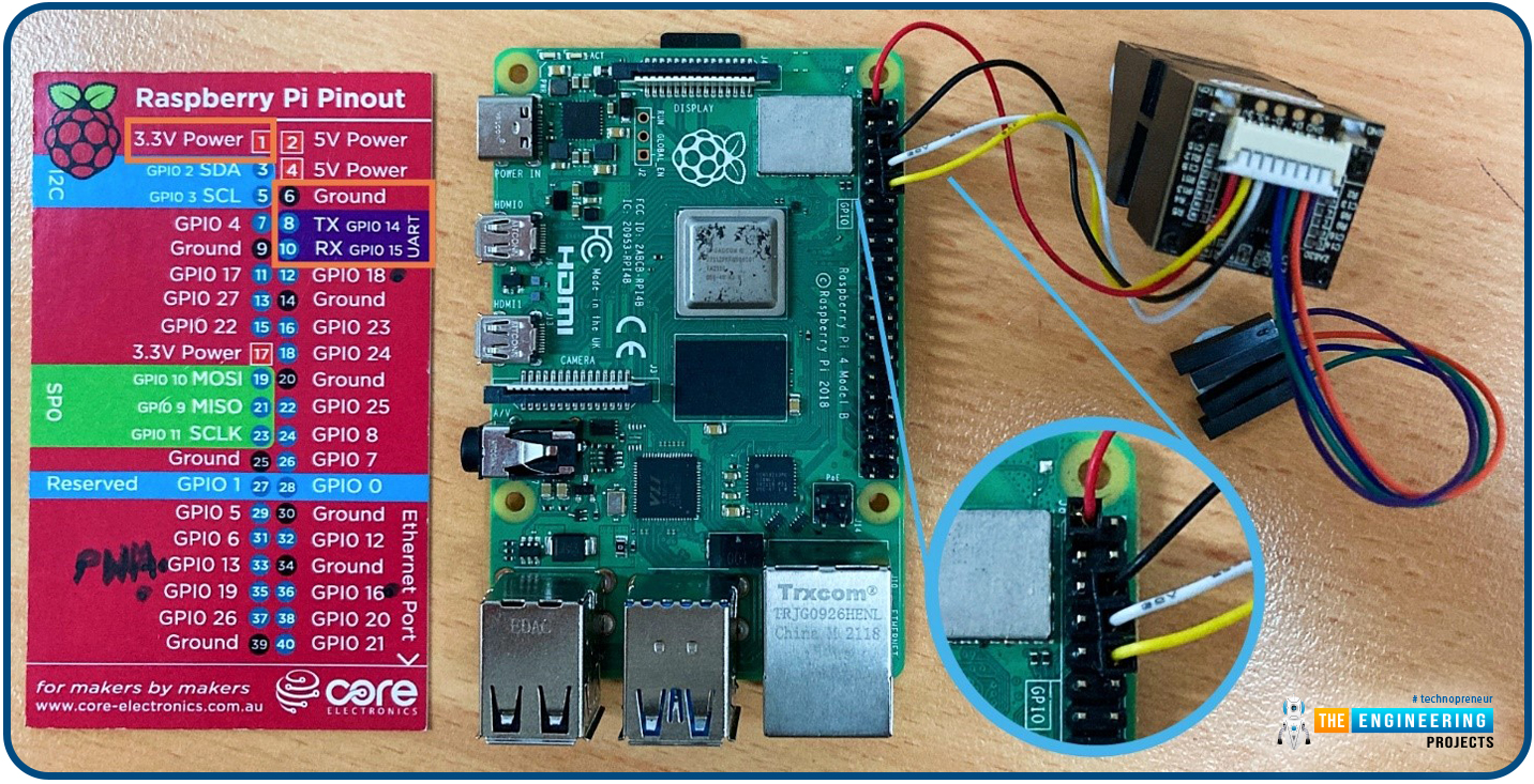
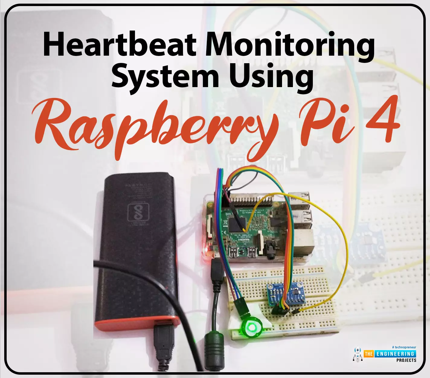
Hello friends, I hope you all are doing great. Welcome to the 11th lecture of Section-III in the Raspberry Pi 4 Programming Series. In the previous tutorial, we discussed the interfacing of the Fingerprint sensor with Raspberry Pi 4. Today, we are going to discuss another sensor named the Pulse rate sensor and will interface it with Raspberry Pi 4.
The field of healthcare monitoring has long been seen as a potential use case for IoT i.e. examining the health instead of regular checkups and local doctors. Using sensors, your vital signs can be monitored and transmitted in real time, allowing a physician on the other side or even an AI to analyze the data and provide an accurate diagnosis. That does seem somewhat futuristic. However, we are making steady progress in that direction and will soon have an autonomous IoT robotic arm operating on us.
In today's tutorial, we'll design a heart rate monitor to keep tabs on a patient's heart rate, using Pulse Rate Sensor and Raspberry Pi. We will display the data(ECG graph) in the Processing IDE.
Here is all, you'll need to put together a Raspberry Pi-based patient monitoring system yourself:
A human vein is positioned directly in front of the sensor's LED. The tip of your finger or the inside of your ear can serve this purpose, but it must be positioned directly over a vein.
The sensor outputs three wires:
We'll use the 3.3V pin on the Raspberry Pi 4 to power up the sensor.
We will use ADS115 to transmit the analog signal from Heart Rate Sensor to Raspberry Pi 4, as the Pi can't read analog signals. Both ADS1015 and ADS1115 are high-precision, low-power analog-to-digital converters. These chips are commonly used with the Raspberry Pi because they operate at 3V3.
Any value from 8-860 samples/sec can be entered into ADS1115's sampling rate field. The shorter time an ADC needs to capture and transform an analog signal, the higher its sampling rate. A gain amplifier is included in the chip and can boost low-voltage signals by a factor of two to sixteen.
Here's the pinout diagram of ADS1115:
Here's the ADS1115's functional block diagram shown below:
A multiplexer takes the analog signals from the inputs and routes them to a programmable gain amplifier. An I2C bus transmits the results of the ADC's conversion of the amplified signal to a microcontroller.
Here are the pin connections of the above circuit:
Since the Analog-to-digital module uses I2C for communication, and we'll be using UART for serial communication, we'll need to activate UART and I2C on the Raspberry Pi by running raspi-config in the terminal.
To proceed, click the Interfacing Options button.
Select I2C and hit Enter.
Now, click the Yes button and hit Enter.
Now, select Ok to proceed.
Pressing the Enter key after selecting Serial will activate the serial port.
Select "no" and hit "enter" to turn off the serial login shell.
To activate the serial, click Yes and then hit Enter.
Choose ok and hit enter to continue.
Click Finish and hit Enter to confirm.
When prompted, type "Yes" and hit enter to reboot.
Now proceed to install the i2c packages.
sudo apt-get install -y python-smbus
sudo apt-get install -y i2c-tools
To determine which device is currently connected and to obtain its I2C address, run the following command:
sudo i2cdetect -y 1
Follow the below lines to install the Python library for the ADC module.
sudo apt-get update
sudo apt-get install build-essential python-dev python-smbus git
cd ~
git clone https://github.com/adafruit/Adafruit_Python_ADS1x15.git
cd Adafruit_Python_ADS1x15
sudo python setup.py install
Now, use the following command to add Processing to your current installation:
curl https://processing.org/download/install-arm.sh | sudo sh
We can now access Processing from the Raspberry Pi's main menu:
We'll use Python and processing codes for the pulse sensor to get the job done.
This code uses I2C communication to connect an ADC module that provides analogue pulse sensor output. Once the pulse sensor's analogue raw production is obtained, the sensor's higher maximum and minimum peak are located. Then calculate the beats per minute by subtracting the times of two extremes. Additionally, the BPM and raw analogue output are transmitted to a serial port, which is then read by the processing IDE. The complete python code for the heartbeat sensor on the Raspberry Pi is provided below.
While developing this code, we used several modules that we imported at the outset for various applications.
import Adafruit_ADS1x15
import serial
import time
We now have variables upon which to perform analyses and take appropriate measures. Also, we made a serial object.
rate = [0]*10
amp = 100
GAIN = 2/3
curState = 0
statechanged = 0
ser = serial.serial("/dev/ttys0",9600)
Now we use this chunk of code to transmit information to the processor.
def send_to_prcessing(prefix,data):
ser.write(prefix)
ser.write(str(data))
ser.write("\n")
Now we have a pre-programmed function to read the pulse sensor and calculate the heart rate.
def read_pulse();
firstBeat=True
seecondBeat=False
ssamplecounter=0
lastBeatTime=0
lastTime=int(time.time()*1000)
th = 525
P = 512
T = 512
IBI=600
pulse=False
adc=Adafruit_ADS1x15.ADS1015()
while True:
signal=adc.read_adc(0,gain=GAIN)
curTime=int(time.time()*1000)
send_to_pressing("S",signal)
samplecounter += curTime - lastTime
lastTime=curTime
N=samplecounter-lastBeatTime
if signal>th and signal>P:
P=signal
if signal(IBI/5.0)*3.0:
if signal
T=signal
The complete Python script for this post is provided for you at the end.
As we saw above, the python code sends a loopback signal to the serial port of raspberry, and the processing code receives that signal. Now we can see the unprocessed analogue input and the beats per minute. Also, the BPM value will be displayed alongside the analogue-value-based graph. We've loaded a few crucial library modules into the processing code.
import processing.serial.*;
PFont font;
serial port
A few factors have been taken into account after this.
char letter;
string words="";
int sensor;
int IBI;
int BPM;
int[] RawY;
int[] scaledY;
int[] rate;
float offset;
color eggshell=color(255,2)
int pulsewindowwidth;
int pulsewindowheight;
int zoom_val=70;
long beat_rec_time;
Then, we set up the serial port and the default graph in the setup method.
void setup()
{
size(500,400); // stage size
PulseWindowWidth=Width -20;
PulseWindowHeight=height -70;
frameRate(100);
textAlign(CENTER);
rectMode(CENTER);
ellipseMode(CENTER);
RawY=new int[PulseWindowWidth];
scaledY=new int[PulseWindowHeight];
We have parsed the received information at this point in the serialEvent method.
void serialEvent(serial port)
{
string inData=port.readstringuntil('\n');
inData=trim(inData);
if(inData.charAt(0)=='S'){
inData=inData.substring(1);
sensor=int(intData);
}
if (inData.charAt(0)=='B'){
inData=inData.substring(1);
BPM=int(inData);
beat_rec_time=millis()/1000;
}
if (inData.charAt(0)=='Q'){
inData=inData.substring(1);
IBI=int(inData);
}
}
We've plotted the graph by mapping the incoming numbers to the graph's dimensions in the draw function.
void draw()
{
background(0);
nostroke();
fill(eggshell); // color for the window background
rect(250,height/2,PulseWindowWidth,PulseWindowHeight);
RawY[RawY.length=1]=(1023=sensor)=212;
offset=map((float)zoom_val/100.0,0.5,1,100,0);
stroke(250,0,0);
nofill();
beginshape();
endshape();
if(millis()/1000>=beat_rec_time=5)
{
BPM=0;
IBI=0;
}
The following lines of code are required to display the BPM over the graph.
fill(255,0,0);
textsize(24);
text("Pulse Sensor Graph",width/2,25);
fill(0,0,255);
textsize(18);
text("IBI:" + IBI + "ms",width -70, height -10);
text("BPM:" + BPM, 50, height-10);
textsize(12);
text("zoom:" + zoom_val + "%", width -50,50);
Here, the code also includes a zoom function, allowing the user to selectively enlarge or reduce the size of the shown plot. The pulse plot can be panned around by pressing - to zoom out and + to zoom in. To adjust the setting, we must first click anywhere on the graph and then use the minus and plus buttons.
void Keytyped()
{
if(key == '+')
{
zoom_val++;
printIn(zoom_val);
}
else if(key == '-')
{
zoom_val--;
printIn(zoom_val);
}
if(zoom_val>100)
zoom_val=100;
else if(zoom_val<=0)
zoom_val=0;
}
Thus, using a Raspberry Pi, one may monitor a patient's heart rate and graph the results. This serial data can also be sent to IoT platforms like ThingSpeak for global data sharing if necessary.
import Adafruit_ADS1x15
import serial
import time
rate = [0]*10
amp = 100
GAIN = 2/3
curState = 0
stateChanged = 0
ser = serial.Serial ("/dev/ttyS0", 9600)
def send_to_prcessing(prefix, data):
ser.write(prefix)
ser.write(str(data))
ser.write("\n")
def read_pulse():
firstBeat = True
secondBeat = False
sampleCounter = 0
lastBeatTime = 0
lastTime = int(time.time()*1000)
th = 525
P = 512
T = 512
IBI = 600
Pulse = False
adc = Adafruit_ADS1x15.ADS1015()
while True:
Signal = adc.read_adc(0, gain=GAIN)
curTime = int(time.time()*1000)
send_to_prcessing("S",Signal)
sampleCounter += curTime - lastTime
lastTime = curTime
N = sampleCounter - lastBeatTime
if Signal > th and Signal > P:
P = Signal
if Signal < th and N > (IBI/5.0)*3.0 :
if Signal < T :
T = Signal
if N > 250 :
if (Signal > th) and (Pulse == False) and (N > (IBI/5.0)*3.0) :
Pulse = 1;
IBI = sampleCounter - lastBeatTime
lastBeatTime = sampleCounter
if secondBeat :
secondBeat = 0;
for i in range(0,10):
rate[i] = IBI
if firstBeat :
firstBeat = 0
secondBeat = 1
continue
runningTotal = 0;
for i in range(0,9):
rate[i] = rate[i+1]
runningTotal += rate[i]
rate[9] = IBI;
runningTotal += rate[9]
runningTotal /= 10;
BPM = 60000/runningTotal
print("BPM:" + str(BPM))
send_to_prcessing("B", BPM)
send_to_prcessing("Q", IBI)
if Signal < th and Pulse == 1 :
amp = P - T
th = amp/2 + T
T = th
P = th
Pulse = 0
if N > 2500 :
th = 512
T = th
P = th
lastBeatTime = sampleCounter
firstBeat = 0
secondBeat = 0
print("no beats found")
time.sleep(0.005)
read_pulse()
By collecting data from a wide variety of sources and transmitting it across a global network of the internet as well as other communication devices that are, in turn, linked to cloud services, the system improves the quality of care provided to patients. It allows doctors to respond to medical emergencies more quickly. In the suggested system, a doctor can do a checkup on a patient at any time, from any location. If the patient's value rises over the level, they should see a doctor, and an urgent message will be sent to them through email. Paralyzed patients and those ordered strict bed rest can benefit from this method since it allows their doctors to keep an eye on them from afar using a Raspberry Pi camera. More sensors can be integrated into the system, and the Internet of Things can be expanded so that everything can be accessed instantly. The model can be improved upon and made available as a mobile application so that users anywhere in the world can access it with minimal effort. In the following lesson, we will learn how to connect a PIR sensor to a Raspberry Pi 4.
Thank you for being here for today's tutorial of our in-depth Raspberry Pi programming tutorial. The previous tutorial demonstrated the proper wiring of the photoresistor sensor to the GPIO pins. Finally, we learned how it might be included in a Python script for data collection and analysis needs. We also looked at the functions of each component in the circuit. However, I'll walk you through installing a Pi 4 Print Server in this guide. While installing the program is straightforward, setting it up so that a Windows network can locate the print server requires a little more effort. Rather than spending hundreds of dollars upgrading to a laser printer, you may easily upgrade your current USB printer to laser quality by installing a print server.
Because of this software, you no longer have to have the printer physically linked to a single computer, and you may place it wherever you choose and share it with as many computers as you like. In addition, it's a fantastic method of printer sharing that eliminates the need for a pricey tower computer to be on and active all the time. CUPS is the program we'll be using to make this happen. Common Unix Printing System, or CUPS, is the foundation of Linux printing applications. But, the program facilitates communication between your computer and printer. It would help if you visited available printing to verify that the CUPS printing software supports your printer model.
Where To Buy? | ||||
---|---|---|---|---|
No. | Components | Distributor | Link To Buy | |
1 | Raspberry Pi 4 | Amazon | Buy Now |
Raspberry Pi 4
Wi-Fi
USB Printer
Since the Raspberry Pi print server is included in the Debian Jessie distribution, setting it up is a breeze. In this lesson, I'll be using Raspbian, so if you're unfamiliar with it and would like to learn how to set it up, check out my guide on how to do so.
We must ensure the Raspberry Pi is up-to-date with the most recent software to get started. Just type in the appropriate instructions into the terminal to accomplish this.
sudo apt update
sudo apt upgrade
We can begin setting up the print software after the Pi 4 has been upgraded. Here, we will be setting up CUPS.
CUPS, short for Common Unix Printing System, is a printing system designed for computers running UNIX-like operating systems. The software transforms the host computer into a print server. A CUPS-enabled server may receive print jobs from various client devices, sort them, and send them to the correct printer for output. Conveniently, this program can handle the administration of your printers, whether they're linked locally through USB or remotely via the network. Using the terminal, enter the following command to install the software. Considering HP has CUPS that support its open source project, HP printers, in particular. Even if your specific printer model isn't listed as being directly supported by CUPS, you may still be able to find a compatible generic driver online that will get the job done. These links will take you to a list of CUPS-compatible printers.
sudo apt install cups
We still have some work to do after CUPS's installation is complete. The first step is to include the pi user in the lpadmin set of users. With this group, the pi user can manage CUPS settings without logging in as the superuser.
sudo usermod -a -G lpadmin pi
To make sure it functions properly on your home network, there is one more thing we must do to CUPS: make it available to every computer on your network. At this time, Cups is configured to refuse connections from addresses outside the local network. By entering the following two commands, we can make it listen to all incoming connections:
sudo cupsctl --remote-any
sudo systemctl restart cups
After this, any machine on the network can send prints to the Pi 4 print server. The following command can be used if you need to know your Raspberry Pi's local IP Address.
hostname -I
If you know your Raspberry Pi's IP address, you can use it to access the website at the address below. Be sure to replace "192.168.1.105" with your IP address.
We'll examine how to configure SAMBA so that Windows can find the Raspberry Pi print server. Furthermore, we will demonstrate how to install a printer using the CUPS interface.
A proper SAMBA configuration is required if you use your print server in conjunction with Windows. To get SAMBA up and running with the CUPS print drivers, we'll have to install it and tweak its settings.
First, check that SAMBA is installed; to do so, we can use the terminal's built-in install command. Just by typing this into the terminal, we can accomplish our goal.
sudo apt install samba
Now that SAMBA is installed on our Pi 4, we can access its config file and make some changes. The following command will cause the file to be opened in the nano text editor:
Sudo nano /etc/samba/smb.conf
Once the file has been opened, it must be scrolled to the end. To do this quickly, press the Control key plus the V key. The following lines should be added or edited once you reach the very end of the file. The file already contained the "[printers]" and "[print$]" sections; all I had to do was update the values to reflect the following.
[printers]
comment = All Printers
browseable = no
path = /var/spool/samba
printable = yes
guest ok = yes
read only = yes
create mask = 0700
[print$]
comment = Printer Drivers
path = /var/lib/samba/printers
browseable = yes
read only = no
guest ok = no
To save the file, hit CTRL+X, Y, and ENTER. SAMBA needs to be restarted to pick up the updated settings. The following command, when entered into the terminal, will restart SAMBA.
sudo systemctl restart smbd
It's easy to set up a printer using CUPS, but first, we need to open the program's graphical user interface. For the IP address of your Raspberry Pi, enter "hostname" into the terminal.
hostname -I
To access the IP configuration page for your Raspberry Pi, type the following into your web browser and enter the IP address you just jotted down. Replace "192.168.1.105" with your IP address when entering this address.
The following homepage is what you should see. Here, we'll go to "Administration" on the main menu.
You'll be directed to Cups's control panel when you click here. On this page, select the "Add Printer" option.
The "Add Printer" screen has been brought up, allowing us to choose the printer we wish to configure Cups with. That printer is a Canon MG2500 series machine. When you've made your print choices, click the "Continue" button.
Ensure the printer is turned on and plugged into the Raspberry Pi through a USB connection if it does not appear here. If your Raspberry Pi still doesn't show up, try restarting it while ensuring your printer is on and connected.
Choose your printer's model from the dropdown menu here. CUPS will automatically identify the printer model and install the appropriate driver when possible. However, this may only sometimes work, so you may need to sift through the list to locate the proper driver manually. Once you've double-checked everything and are pleased, click the "Add Printer" button.
After completing the steps on this screen, the printer will have been added successfully. Here, you can give it a name and a summary that mean whatever you choose. If you have more than one printer in your residence, specifying its location will make your life easier. If you want other computers to be able to use the printer, you must also turn on "Share This Printer." If everything looks good, hit the "Continue" button.
After finishing the printer setup process, you will see the screen shown in the image below. Several of the printer's more nuanced settings are accessible through this panel—the number of pages printed, the quality of the printout, and so forth.
Having finished setting up our Raspberry Pi print server, we will now discuss how to add it to Windows. Having SAMBA set up earlier in the course should make this step less painless.
Installing a CUPS printer on Windows requires selecting the driver that will allow Windows to communicate with and comprehend the printer. Launching "My Computer" or "This PC" and then clicking "network" in the left-hand navigation pane is a quick method to get to Windows' network page, where you can get started. When you get there, you should see a screen like the one below, where your Raspberry Pi's hostname (in my instance, RASPBERRYPI) is displayed. If you double-click your Raspberry Pi's share, it may prompt you to log in. If entering anything other than "enter" fails to log you in, try "pi."
The printers used with your Pi 4 print server should now be displayed on the screen. Select the printer you wish to use by double-clicking on it.
You'll see the cautionary message below if you try to double-click this. Select "OK" to proceed with the tutorial.
Select your printer brand on the left, and then select your printer model from the available drivers for that brand on the right. If your printer isn't listed here, you can identify its model online and install the necessary drivers. For me, that meant tracking down the Canon MG2500 series. When you've decided which printer to use, you may move forward by clicking the "Ok" button.
The procedure will now initiate a link to your printer. Select "Printer" > "Set as Default Printer" to make this the system's default printer.
Now that the printer has been installed on your computer, you can use it with any application that supports printing. By printing a test page, you may verify that the printer is configured correctly.
If you're having trouble printing a file, check to see if you've picked the correct printer driver in CUPS and Windows. Ensure the printer is turned on as well; the Canon MG2500 series, for example, do not immediately restart when a print job is delivered. Adding Apple AirPrint capability to your Pi 4 print server is a great way to expand its capabilities.
Apple's AirPrint printing technology eliminates the requirement for users of Apple products to acquire and install the separate printing software. By adding AirPrint functionality, you may quickly and effortlessly print from your iOS smartphone to any nearby printer. You can run an AirPrint server from your Raspberry Pi, and Cups is the software that will power it. It will take care of talking to your printer on your Raspberry Pi's behalf.
The "Avahi daemon" must be set up before AirPrint may be used on your computer. The following command will install the package onto your Raspberry Pi.
sudo apt install avahi-daemon
Using this package, you can make Apple's Zeroconf design a reality. Bonjour has become widely used to refer to this type of network architecture. Using Bonjour, AirPrint can link disparate gadgets like an iPhone and a Raspberry Pi. Once you've selected the files you'd like to print, the Bonjour daemon will forward them to the designated printer.
Let's restart the machine to see whether the AirPrint server has worked appropriately, and everything is ready. Execute this command to force the Raspberry Pi to restart.
sudo reboot
After rebooting your Raspberry Pi, you can check to see if anything went wrong. This should get you to the point where you can print from any AirPrint-enabled device.
Have you succeeded in following this guide and setting up a Pi 4 network print server? If you've followed these steps carefully, your Raspberry Pi should be ready to function as a network AirPrint server. We were able to accomplish this by putting the Avahi daemon in place. This daemon implements the bonjour protocol used by AirPrint. Feel free to leave a message below if you have any thoughts, suggestions, or problems you'd want to discuss. The following tutorial will review the steps for monitoring a patient's heart rate with a Raspberry Pi 4.
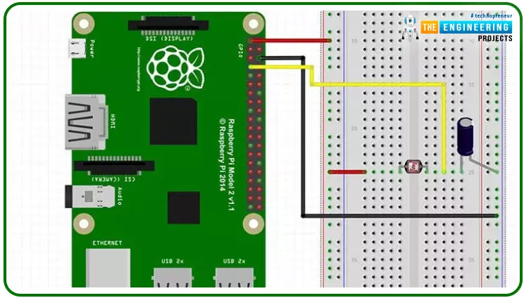
Hello friends, I hope you all are doing great. Today, we are going to start Section-III of our Raspberry Pi 4 Programming Course. In this section, we will interface different Embedded Sensors with Raspberry Pi 4. Today's our first lecture in Section-III, so I am going to interface a simple LDR sensor with RPi4.
So, let's get started:
The following items are required to finish this Raspberry Pi photoresistor module guide. You don't need a breadboard to accomplish this, but having one would be helpful.
It is a common practice to employ photoresistors to determine the presence or absence of visible light or to quantify the amount of light hitting a particular surface. Their resistance is exceptionally high in the dark, reaching up to 1M ohm, but when subjected to light, the LDR sensor's resistance reduces rapidly, often to only a few ohms. Light-dependent resistors (LDRs) are nonlinear devices whose sensitivity shifts depending on the incident wavelength of light. To protect their ecosystems, some nations have outlawed the use of lead and cadmium in LDRs.
By analyzing the electromagnetic radiation in the "Infrared", "Visible" and "Ultraviolet" regions of the electromagnetic spectrum, Light Sensors can produce an output signal indicative of the brightness of the surrounding light. A passive device called a light sensor transforms this "light energy," which can come from either the visible or infrared regions of the spectrum, into an electrical signal. Because they convert the energy of light (photons) into a usable form of electricity, light sensors are also referred to as photoelectric devices or photo sensors (electrons).
There are two primary types of photoelectric devices: those that produce electricity when exposed to light (photovoltaics, photoemissive, etc.) and those that modify their electrical properties when exposed to light (photoresistors, photoconductors, etc.).
The light-dependent resistor (LDR) sensor is used to detect the intensity of light in the surroundings. The LDR is a device constructed from a sensitive semiconductor material i.e. cadmium sulfide, which undergoes a dramatic shift in electrical resistance when exposed to light, going from several 1000 Ohms in the dark to just a few Ohms, when illuminated.
Most photoresistive light sensors employ cadmium sulfide(CdS). However, other semiconductor substrate materials like lead sulfide (PbS), lead selenide (PbSe), and indium antimony (InSb) can detect light intensity as well. Since cadmium sulfide has a spectral response curve similar to the human eye's and can be modulated with a handheld torch, it is utilized to create photoconductive cells. The peak wavelength at which it is most sensitive is typically between 560-600nm (nanometers), making it part of the visible spectrum.
The ORP12 cadmium sulfide photoconductive cell is the most widely used photoresistive light sensor. This photosensitive resistor's spectral response is concentrated around 610 nm in the yellow-to-orange part of the spectrum. When the cell is in the dark, its resistance is extremely high at around 10M's, but it drops to about 100's when illuminated (lit resistance). As the resistive path zigzags across the ceramic substrate, the dark resistance increases and the dark current drops. Because of its low price and wide range of possible applications, the CdS photocell is frequently used in auto-dimming systems, light- and dark-sensing controls for streetlights, and photographic exposure meters.
Below is an illustration of how a light-dependent resistor can be used as a light-sensitive switch.
This simple circuit for detecting light consists of a relay activated by exposure to sunlight. The photoresistor LDR and the resistor R1 make up a potential divider circuit. In the absence of light, the LDR's resistance rises into the Megaohm (M) range, and as a result, the transistor TR1 receives zero base bias, turning the relay off. The LDR's resistance drops in response to more light, elevating the base bias voltage at V1. When the base bias voltage of transistor TR1 reaches a certain threshold, as defined by the resistance R1 in a potential divider network, the transistor turns "ON," activating the relay, which controls some external circuitry. With a return to darkness, the LDR's resistance rises, reducing the transistor's base voltage and turning "OFF" the transistor and relay at a predetermined level of illumination established by the potentiometer circuit.
Changing the relay's "ON" or "OFF" point to a custom brightness is as simple as swapping out the fixed resistor R1 for a potentiometer VR1. The switching end of a simple circuit like the one depicted above may need to be more consistent owing to fluctuations in temperature or supply voltage. Using the LDR in a "Wheatstone Bridge" configuration and substituting an Operational Amplifier for the transistor makes it simple to construct a light-activated circuit with increased sensitivity.
To build the circuit of the LDR sensor with RPi4, follow these instructions. You can also refer to the
below
circuit diagram:
Now is the time to start writing Python code for LDR:
This project's code is simple and will let us know whether it's bright outside, partly cloudy, or overcast. The lack of analog inputs on the Pi is the primary limitation of this device. So far, we have only worked on the digital modules, but here we need an analog pin to get a reliable reading of the input resistance variation. So, we'll count how long the capacitor takes to recharge and then set the pin high. This is a quick but unreliable way to gauge the ambient light level.
Here I will quickly go over the code for the LDR sensor with Raspberry Pi. As a first step toward establishing a connection with the GPIO pins, we import the necessary GPIO package. The time package is also imported, allowing us to schedule script inactivity.
#!/user/local/bin/python
import RPi.GPIO as GPIO
import time
Next, we change the GPIO modes to GPIO.BOARD so that the pins used in the script match the hardware. One variable only needs to be set because there is just one input/output pin. If you use a specific GPIO pin, assign its number to this variable.
GPIO.setmode(GPIO.BOARD)
#define the pin that goes to the circuit
pin_to_circuit = 7
The following function we'll look at is RC time, and it takes a single input: the circuit's PIN. In this code, we set the value of a variable named count to zero, and then, when the pin is set to high, we return that number. Our pin is then configured as an output before being brought low. Then we let the program rest for ten milliseconds. When this is done, the pin is converted to an input, and a while loop is started. In this loop, the capacitor is charged until it is around 3/4 full, at which point the pin swings high. Once the pin is set to high, we send the count back to the primary method. This number can be used to toggle an LED, trigger an action, or be stored to compile data on brightness fluctuations.
def rc_time (pin_to_circuit):
count = 0
#Output on the pin for
GPIO.setup(pin_to_circuit, GPIO.OUT)
GPIO.output(pin_to_circuit, GPIO.LOW)
time.sleep(0.1)
#Change the pin back to the input
GPIO.setup(pin_to_circuit, GPIO.IN)
#Count until the pin goes high
while (GPIO.input(pin_to_circuit) == GPIO.LOW):
count += 1
return count
#Catch when the script is interrupted, clean it up correctly
Try:
# Main loop
while True:
print(rc_time(pin_to_circuit))
except KeyboardInterrupt:
pass
finally:
GPIO.cleanup()
Even though this is a trivial procedure, I'll run through it fast so you can get it up and work on your Pi without any hiccups. I am employing Raspbian, the operating system used in all the guides here. Read my Raspbian installation instructions if you need assistance. In most circumstances, all the necessary software will already be installed. Using git clone, the source code can be downloaded. Here's a command that will carry out your request.
git clone https://github.com/pimylifeup/Light_Sensor/
cd ./Light_Sensor
The code can also be copied and pasted, but only into a Python script. When working with Python code, my preferred text editor is nano.
sudo nano light_sensor.py
To save your changes and leave the file, press CTRL+X then Y. Finally, the following command will execute the code.
sudo python light_sensor.py
Hopefully, you've fixed the script and are now getting readings that accurately reflect the light levels on the sensor. Be bold about posting a comment if you need help.
A light sensor can be implemented in a variety of circuitry contexts. Some that sprang to mind when I was penning this guide are as follows:
An LDR can detect the onset of daylight, allowing for the activation of an alarm to rouse you from sleep. With a reliable program and sensor, you may set the alarm to increase in volume as daylight fades gradually. One way to keep tabs on your garden is to use a light sensor to measure how much sun each section of your garden is getting. This could be helpful knowledge if you're planting anything that needs a lot of sun or vice versa. Using the Room Monitor, you can ensure the lights in a particular room are switched off whenever no one is there. This might be set up to send you an alert if the light is found in an unexpected place.
This fantastic sensor has a wide variety of applications. However, if you need something more precise than a photocell, consider the Adafruit dynamic range sensor. You had no trouble installing this light sensor on your Raspberry Pi. Please comment below if you have any issues or suggestions or think I need to include something. In the next section, we'll see how to interface a Soil Moisture Sensor with Raspberry Pi 4. Till then, take care. Have fun!!!