Hello friends! In this tutorial, we will install the Arduino Pro Mini Library for Proteus and build a simple blinking-LED simulation. We will start with the library files, prepare a program for the correct board variant and then load its HEX file into the simulated microcontroller.
Arduino Pro Mini Library for Proteus
Latest version: Arduino Pro Mini Library for Proteus V4.0 (October 2026), with working PWR and 13 LEDs, a RESET button and a built-in serial monitor
Earlier versions: V3.0 (2023) · V2.0 (2021) · V1.0 (2015, this tutorial)
Other boards: UNO · Mega 2560 · Mega 1280 · Nano · Mini (V4.0)
All six V4.0 boards in one package: Arduino Library for Proteus V4.0
Helping Tools
- Serial Monitor Advance: a serial terminal window for the UART of your board
- Serial Monitor Expert: the serial monitor with extra debugging tools
- LCD Library for Proteus V3.0: 16x2, 20x4 and I2C LCDs to show your readings
The Pro Mini is a useful choice when you want a compact Arduino board without a permanently attached USB interface. That makes the finished assembly smaller, but it also means you must think about voltage, clock speed and the programming connection when you build the physical project. We will explain those differences as we go.
This article retains the original V1.0 library download and simulation images. The basic installation and firmware workflow remains useful, while the newer releases linked below provide their own additional features. Begin with one known configuration before combining a different board model, compiler target and supply arrangement.
Understand the Arduino Pro Mini Variants
The Pro Mini belongs to the classic AVR Arduino family. Common ATmega328P versions use either a 5 V supply with a 16 MHz clock or a 3.3 V supply with an 8 MHz clock. Older ATmega168 variants also exist, so identify the processor rather than choosing a target from the board's appearance alone.
The Arduino AVR core's official board definitions show the separate processor and clock options. These settings affect compiled timing and available program memory. Selecting an 8 MHz option in the IDE does not physically change the oscillator fitted to a board.
| Configuration | Logic supply | Clock | What must match |
|---|---|---|---|
| ATmega328P Pro Mini, 5 V | 5 V | 16 MHz | IDE processor option, simulated clock and hardware voltage |
| ATmega328P Pro Mini, 3.3 V | 3.3 V | 8 MHz | IDE processor option, simulated clock and peripheral signal levels |
| Older ATmega168 board | Depends on variant | Depends on variant | Exact processor and memory limits as well as clock |
For the first exercise, use the 5 V, 16 MHz configuration and confirm the library model's clock property. If you later investigate the 3.3 V variant, rebuild for 8 MHz and check whether the selected simulation model exposes the electrical behavior you need. Changing a clock property alone does not establish that a model accurately reproduces a different regulator or supply circuit.
Why the Board Has No USB Socket
A physical Pro Mini normally relies on an external USB-to-serial adapter for bootloader uploads, or a suitable ISP programmer for direct programming. The removable adapter keeps that interface out of the final circuit when it is no longer needed.
In Proteus, we will load the application HEX directly through the Program File property. That operation does not require a real adapter, a COM port or a physical Pro Mini connected to the computer. Keeping these two workflows separate makes installation much easier to understand.
Download and Install the Pro Mini Library
Download the original Arduino Pro Mini Library for Proteus from the attachment below. Extract the archive before copying its files into the directory used by your Proteus installation.
Arduino Pro Mini Library for ProteusThe original package contains ArduinoProMiniTEP.LIB and ArduinoProMiniTEP.IDX. Keep those files together from the same release. They are Proteus component-library files, not Arduino source libraries, and should not be placed in the Arduino IDE's sketchbook libraries folder.
- Close Proteus while installing the library.
- Extract the downloaded archive to a temporary working folder.
- Find the library directory configured for your Proteus installation.
- Copy the LIB and IDX files into that directory.
- Restart Proteus and open the component picker.
- Search for Arduino Pro Mini and select the TEP component.
- Place the board on a new schematic so that you can test it independently.
Library paths differ between installations. If you cannot locate the correct directory, follow our guide on adding libraries in Proteus 8. Avoid guessing several paths and distributing duplicate copies, because you may later update a file that Proteus is not using.
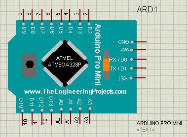
After installation, the original board component should resemble the image below. Its appearance helps you identify the library, but successful placement does not by itself demonstrate that every processor peripheral is supported by your Proteus configuration.
Newer Library Versions
The Pro Mini Library V4.0 has its own guide covering working PWR and pin-13 LEDs, a reset button and a built-in serial monitor. Previous versions are documented in the V3.0 tutorial and V2.0 tutorial.
Choose a release deliberately and use its matching instructions. The original archive attached here does not acquire newer interactive features because another version has been published. Keep an existing project's library files available before replacing a component with a different model.
Plan the Circuit Connections
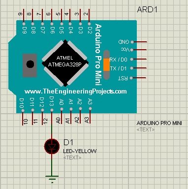
For the initial test, we need the Pro Mini model, one LED and one resistor. D13 will be the LED output. Connect the resistor and LED in series from that output to ground, with the LED anode facing the positive output.
| Signal | Purpose | Connection for this exercise |
|---|---|---|
| D13 | Digital output | Series resistor followed by LED anode |
| GND | Reference and return | LED cathode and circuit ground |
| VCC | Regulated logic supply on hardware | Match the board's voltage variant |
| RAW | Input to the board's regulator on hardware | Use only within the actual regulator and board limits |
| RX and TX | Hardware UART | Optional terminal connection after blinking works |
| RESET | Restart input | Keep in its normal inactive state unless intentionally resetting |
RAW and VCC are not interchangeable labels. Supplying a higher voltage directly to VCC bypasses the intended regulation path. On a real board, check the regulator fitted to that particular module, its allowable input, dropout and thermal dissipation before choosing a supply.
For example, a linear regulator dropping 9 V to 3.3 V while supplying 60 mA would dissipate approximately (9 - 3.3) × 0.060 = 0.342 W, excluding its own operating current. Whether that is acceptable depends on the package, board copper and ambient conditions. A schematic that runs successfully does not measure this temperature rise.
Calculate the LED Resistor
Use R = (Voutput - VLED) / ILED as an initial estimate. With a 5 V output, a red LED drop of 2 V and a desired 5 mA, the result is 600 ohms. Choosing 680 ohms gives about 4.4 mA with those assumed voltages.
At 3.3 V, the same 680-ohm resistor gives approximately (3.3 - 2.0) / 680 = 1.9 mA. This illustrates why a resistor selected for one voltage may produce a different brightness at another. Use the actual LED and output characteristics when deciding whether the result suits your project.
The resistor is still needed when using a simulated LED. It makes the schematic reflect the circuit you intend to build and avoids teaching a direct connection that could overload a real pin. For several outputs, also check total current through the controller's ports and supply pins.
Prepare the Arduino Program
Open Arduino IDE, select Arduino Pro or Pro Mini from the Arduino AVR Boards platform, then select the processor and voltage/clock option matching your simulation. For the first exercise here, select the ATmega328P option labeled 5 V, 16 MHz.
Enter the following sketch. It switches D13 on for 250 milliseconds and off for 750 milliseconds, giving a one-second cycle with a 25 percent duty cycle. Using unequal intervals makes it easy to distinguish this build from the familiar half-second blink example.
const byte ledPin = 13;

void setup() {
  pinMode(ledPin, OUTPUT);
  digitalWrite(ledPin, LOW);
}

void loop() {
  digitalWrite(ledPin, HIGH);
  delay(250);
  digitalWrite(ledPin, LOW);
  delay(750);
}
Compile the sketch and export its compiled binary. For this AVR target, select the ordinary application HEX file for direct loading into Proteus. If you are unsure where the IDE places it, the guide on getting a HEX file from Arduino explains the workflow.
Keep the exported program in a stable project folder. Temporary compiler directories can disappear or contain several builds with similar names. Give the file a descriptive name that includes the intended clock when you are comparing variants.
Load the HEX File into Proteus
- Double-click the placed Pro Mini component.
- Locate its Program File property.
- Browse to the exported application HEX file.
- Check the modeled processor and its clock setting.
- Confirm the circuit connections and close the properties dialog.
- Start the simulation and observe the external LED.
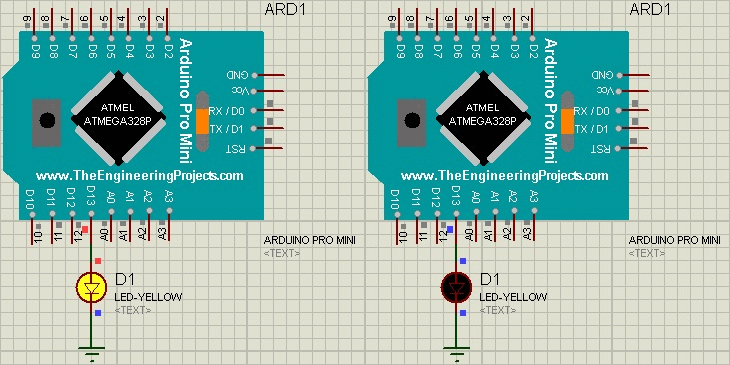
The original animation below demonstrates blinking with the historical project. Your new sketch uses the specified 250/750-millisecond timing, so its duty cycle may differ from that animation. Compare against your own code and simulated timebase rather than expecting identical animation frames.
After every source change, compile and export again. Proteus executes the selected binary; it does not automatically discover that an open Arduino sketch has changed. When results seem unchanged, confirm the selected file path before rewriting the circuit.
Check Clock and Timing Consistency
The compiled program assumes a particular clock frequency. If a 16 MHz build runs at 8 MHz, its timing generally stretches by a factor of two. In this example, the intended 250-millisecond on-time becomes approximately 500 milliseconds, and the 750-millisecond off-time becomes approximately 1.5 seconds.
The reverse mismatch makes the program run too quickly. UART baud generation and other timer-based behavior also change, so an incorrect clock can produce several apparently unrelated symptoms. Correct the configuration before adjusting delay values to compensate for it.
Measure on-time and off-time separately if you have a logic instrument available. Frequency is the reciprocal of their sum: f = 1 / (0.250 + 0.750) = 1 Hz. Duty cycle is 0.250 / 1.000 × 100 = 25 percent. A correct frequency with the wrong duty cycle points to a different issue than both intervals being scaled equally.
Understand Physical Programming Connections
When you transfer the sketch to a real Pro Mini, use an adapter whose supply and signal levels match the board. Check the adapter documentation: a jumper marked 3.3 V may change its power output without necessarily changing every UART signal level.
| Adapter signal | Pro Mini connection | Reason |
|---|---|---|
| TX | RX | Adapter sends data to the board |
| RX | TX | Adapter receives data from the board |
| GND | GND | Establishes a common voltage reference |
| Compatible supply output | Appropriate board supply input | Power only if the adapter and board arrangement permit it |
| DTR or supported reset signal | Matching auto-reset connection | Starts the bootloader at the required upload time |
Follow the markings of the actual six-pin connector rather than assuming two adapters use the same orientation. If the board is already powered, decide whether the adapter's supply connection should remain disconnected. Avoid connecting two independently driven supply outputs together without an arrangement designed for that purpose.
A direct ISP upload and a serial bootloader upload are different operations. ISP uses programming signals to write the microcontroller directly and may replace the bootloader. Neither process is required for the direct HEX-loading simulation described here, so do not troubleshoot a Proteus error by randomly rewriting a physical board's bootloader.
Use Serial Output for Debugging
Once the LED test works, a short Serial.print message can confirm that the program reaches a particular section. Initialize the UART at a known rate, connect the Pro Mini TX signal to a simulated terminal's RX input and configure matching baud and framing.
If the LED timing is correct but terminal text is corrupted, check the terminal configuration and signal direction. If both are wrong, recheck the clock. If no message appears, establish whether the startup code executes and whether the selected firmware actually contains that message.
Moving from a Blink Test to a Sensor Project
Add one peripheral at a time after saving the working blink project. Record its power supply, interface and assigned pins. For an I2C sensor, include its address and the voltage to which the pull-up resistors connect. For an SPI peripheral, record the chip-select pin separately from the shared bus signals.
Do not connect a 5 V output directly to a 3.3 V-only input without confirming compatibility. A board running at 3.3 V can simplify some sensor interfaces, but it does not make every module compatible. Modules may contain regulators, pull-ups or level translators that change the appropriate connection.
Low power is another reason to consider the Pro Mini, but removing the USB interface alone does not establish a battery-life figure. The regulator, power LED, sensor current, sleep mode and measurement schedule all contribute. Estimate battery life using measured average current and realistic usable battery capacity.
For example, a usable capacity of 500 mAh with an average 5 mA load gives an ideal arithmetic estimate of 100 hours. Converter losses, temperature, battery chemistry and discharge limits can reduce that value. Treat the estimate as a planning calculation and check the actual assembly.
Troubleshooting the Pro Mini Simulation
| Symptom | Likely checks |
|---|---|
| Board cannot be found | Extracted library pair, correct directory and component search |
| Simulation reports a missing model | Required processor support and the selected library release |
| LED does not blink | HEX selection, D13 wiring, LED polarity and ground |
| Blinking is twice as slow | 16 MHz firmware running on an 8 MHz configuration |
| Serial output is unreadable | Clock, baud rate, framing and signal direction |
| Hardware upload fails | Correct adapter levels, processor option, bootloader and reset timing |
Keep installation failures separate from application failures. If the component is found and a minimal sketch runs, reinstalling the library is unlikely to fix a sensor address conflict or a blocking loop. Reduce the circuit to the smallest failing example and preserve the exact error message.
Review and Related Board Libraries
The Pro Mini model is helpful for developing firmware around a compact AVR board and understanding the effect of clock selection. It does not replace checking a physical regulator, adapter voltage or sensor interface. The best first milestone is a small circuit with clearly measured behavior that you can reproduce after changing the program.
You can compare this board with the classic Nano library, or install the original combined Arduino library. The combined V4.0 package and individual guides for UNO, Mega 2560, Mega 1280, Nano and Mini remain available.
Additional tools include Serial Monitor Advance, Serial Monitor Expert and LCD Library V3.0. Follow the selected tool's wiring and firmware requirements when adding it.
Frequently Asked Questions
Is the Pro Mini the same as the Arduino Mini?
No. They are separate board designs. They may use related processors, but pin arrangement, programming connections and supplied library components must be checked independently.
Can I select the UNO board in Arduino IDE?
Some simple code may run on compatible hardware, but choose the correct Pro Mini target and clock for a reproducible build. A working blink under a mismatched board selection is not proof that every peripheral assumption is correct.
Does a 3.3 V selection make a five-volt board safe for every sensor?
No. A software menu does not change the physical supply or signal voltages. Use the correct hardware variant and verify the sensor's electrical interface.
Why does the model not show a built-in serial monitor?
The original V1.0 model and newer V4.0 model have different features. Use a separate simulated terminal with the older model, or follow the V4.0 guide with its corresponding package.
Do these examples prove that my hardware is working?
No. They explain the expected behavior and setup procedure. Compile and run your chosen configuration, then check the physical circuit separately before depending on it in a finished project.