

3 phase induction motor is the one which operates on three phase AC supply. It is the most commonly used motor for high load and industrial applications. I would discuss advantages of a 3 phase induction motor later in this article. Three phase induction motors are further divided into two types; Squirrel Cage Induction Motor and Wound Rotor Induction Motor based on the construction of rotor. First of all, I am going to discuss about the construction of 3 Phase Induction Motor and then I will throw some light on its working.
Construction of 3 Phase Induction Motor
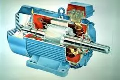
Talking about its construction, like any other motor a 3 phase induction motor consists of a rotor and a stator. Let’s revise the basic knowledge about rotor and stator first.
- Rotor is the rotating part while stator is the stationary part of motor.
- Rotor is separated from the stator by a small air gap.
- Stator is actually a cylindrical frame inside which the cylindrical core of rotor rotates.
- The stator of motor has slots on its internal side to carry the winding circuitry. This circuit is supplied with AC power. This winding is called stator winding.
- As I told earlier, rotor is a cylindrical core which is laminated and it acts as the output shaft of motor.
- Rotor of motor has also slots to carry conductors. These conductors make up rotor winding.
- Now, I am going to discuss types of rotor.
Types of a 3 Phase Induction Motor
Based on the rotor construction, a 3 phase induction motor is further classified into two types:
- Squirrel Cage Induction Motor
- Wound Rotor Induction Motor
Squirrel cage induction motor is cheaper than wound type, and because of the absence of brush assembly it requires less maintenance due to less wear problems.
Squirrel Cage Induction Motor
- First I will talk about squirrel cage type of induction motor.

- The rotor of a squirrel cage type motor consists of bars of copper.
- These copper bars or conductors extend out from the rotor length and are fixed in slots of rotor core.
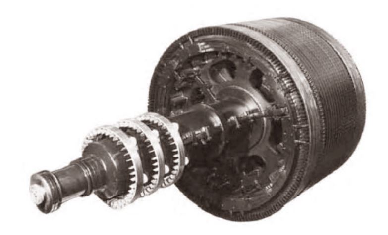
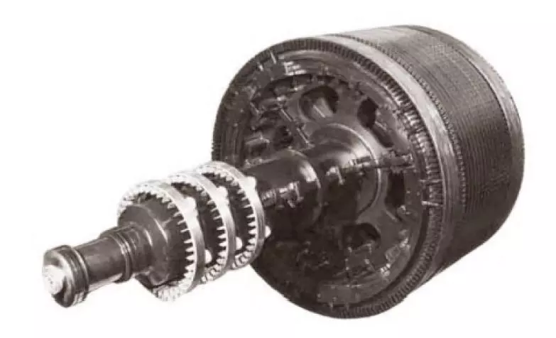
- The bars which are extended out are short circuited together by means of copper rings on each sides as shown in figure.
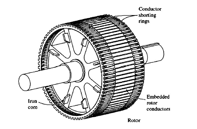
- This type of construction of bars and end rings is similar to a squirrel cage, from where the name comes. Next is the construction of a wound type induction motor.

Wound Rotor Induction Motor
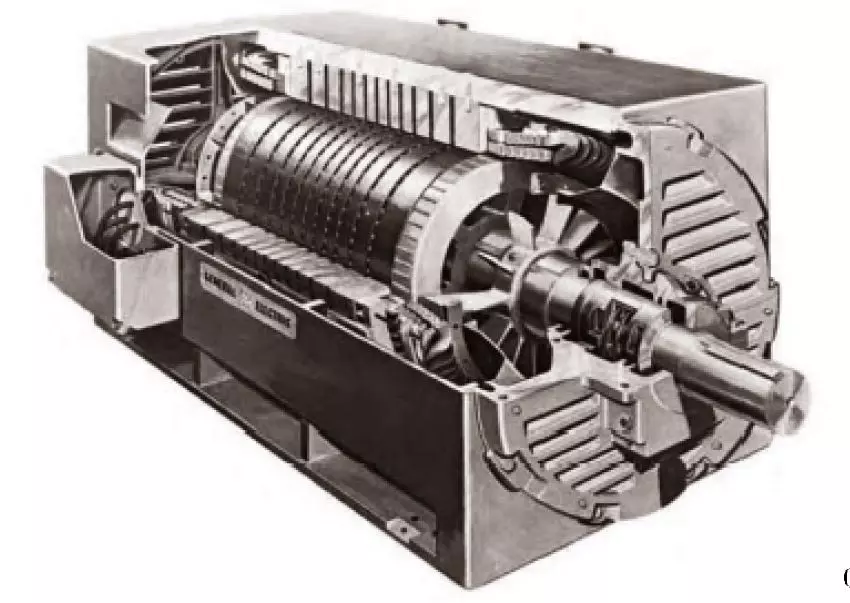
- In wound rotor induction motor, there is a 3 phase winding which is similar to stator’s winding.
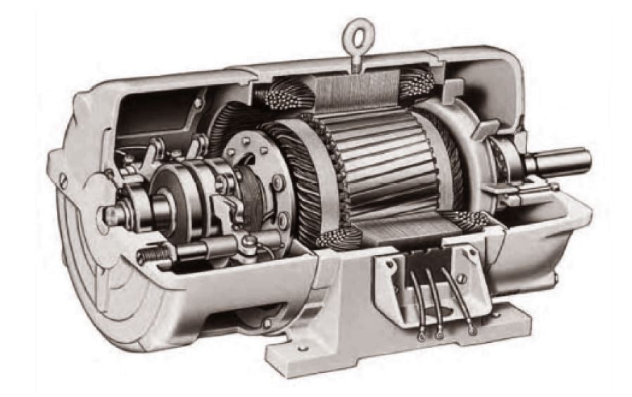
- This winding is placed uniformly on slots of the rotor.
- The endings of these windings are connected to 3 slip rings on the shaft.
- Each phase out of three phase is connected to one slip ring.
- The slip rings of each phase rotate with rotor and are further associated with brushes which are stationary. The construction is shown in figure.
- That’s all about construction and classification of 3 phase induction motor. Now let’s discuss about working principle.

Working Principle of 3 Phase Induction Motor
In this section of the article, I am going to talk over the working principle and operation of a 3 phase induction motor. Before diving into the details, let’s revise some basic concepts and laws that govern its operation.
Faraday’s Law:
- Faraday’s law is the basic law of electromagnetic induction which plays the most important part in the working of a 3 phase induction motor.
- According to which an emf is induced in a conductor when it is placed in a varying magnetic field or if the conductor is rotated in a magnetic field. In other words, emf is induced whenever there is a relative motion of the conductor and magnetic field.
- Also, if the conductor is a closed circuit, a current is produced termed as induced current.
Lenz’s Law:
- Following Faraday’s Law as explained earlier in the previous point, when an emf is generated in a conductor, its polarity would be such that it will produce current whose magnetic field will oppose the change that is producing current. This is called Lenz’s law.
Lorentz Force:
- Lorentz force is the force which is responsible to move the conductor in the magnetic field.
- Whenever, a current is flowing in a conductor in the presence of a magnetic field, the conductor will experience this force.
That was all about the basics, now I am going to throw light on its working and development of torque.
First of all, a 3 phase AC voltage is supplied to the stator windings due to which a 3 phase current starts flowing in it. These currents flowing in windings will produce a magnetic field that rotates due to AC oscillations. Now, the flux of this rotating magnetic field will cross the rotor conductors and a voltage is induced in them which depends on three factors; the relative speed of conductor and magnetic field, magnetic flux density and length of the conductor. The result of this induced voltage is the generation of induced current in rotor, which lags behind the rotor’s induced voltage. This leads to the production of rotor’s magnetic field. Finally, the torque induced is the scaled product of stator magnetic field and rotor magnetic field and the rotor of 3 phase induction motor starts rotating.
The rotor of induction motor never achieves the synchronous speed to keep itself rotating as I discussed in my article on Induction Motors. Next, I am going to give some equations and formulas for calculating synchronous speed, slip and rotor frequency of 3 phase induction motor.
- Let’s first talk about Synchronous speed. Synchronous speed is the speed of rotating magnetic field of stator. It is represented as n_s. If “f” is the frequency of AC supply and “p” is the number of poles then n_s = 2*f/p.
- Second term on the list is slip of induction motor. Slip is denoted by “p” and it is the difference of synchronous speed and rotors mechanical speed. If synchronous speed is n_s and rotor speed is n_r then s = (n_s - n_r). Slip is also expressed as a ratio per unit or as percentage of synchronous speed. This expression is used to find rotor speed, when slip of motor is known.
- Rotor frequency is also discussed for 3 phase induction motors. This frequency is directly proportional to the slip. Represented by f_r, it is expressed by the following formula: f_r = s * f
That was all about the working of a 3 phase induction motor, so before telling the advantages I am going to give a brief idea on its equivalent electric circuit.
Equivalent Circuit of a 3 Phase Induction Motor
A 3 phase induction motor is also called a rotating transformer as working principle of both are quite similar. So, the equivalent circuit is also similar to that of a transformer as shown in image. Right side of the image shows rotor circuit and left side is stator side.
- On the stator side, there is resistance and self-inductance in stator windings. R1 is the resistance of stator and X1 is stator reactance.
- E1 is the stator voltage. Er is the induced voltage in rotor windings while Vp is the applied voltage to the machine.
- On the rotor side, Rr is the rotor resistance and Xr is the rotor reactance.
- A_eff denotes the turn ratio of a transformer which associates E1 and Er.
- Xm is the magnetizing reactance.
- I1 is the stator current while Ir is the current in rotor.
In the last section of my article, I am gonna give some advantages of a 3 phase induction motor.
Advantages
- Let’s now take a look on the advantages of a 3 phase induction motor.
- 3 phase induction motors are simple and require easy maintenance.
- They are preferred because of low price.
- They can be used in rugged environments.
- A 3 phase induction motor is brushless so the problem of maintenance and wear is avoided.
- Speed of this motor can also be controlled.
