Today, I am going to share my knowledge about Introduction to LM358. LM-358 consists of two independent high gain frequency compensated operational ampl...
Hello everyone! I hope you all will be absolutely fine and having fun. Today, I am going to share my knowledge about Introduction to LM358. LM-358 consists of two independent high gain frequency compensated operational amplifier. They are specially designed to operate from a single supply or split supplies over a wide range of voltages.
LM-358 have lot of amazing features associated with them. These features include wide supply ranges, low supply current drain, independent of supply voltage, wide unity gain bandwidth, ground includes I common mode input voltage range, low input bias, open loop differential voltage gain, internally frequency compensation etc. LM 358 has a lot real life applications e.g. Operational Amplifier (Op-amp) circuits, transducer amplifiers, DC gain blocks etc. LM-358 is available in as small size as chip. It is most commonly used device due to its cost efficiency.
[otw_is sidebar=otw-sidebar-7]
Introduction to LM358
LM 358 consists of two independent high gain frequency compensated Operational Amplifier (Op-amp). These are designed for the operation of this device from single supply or split supplies for a wide range of voltages. LM-358 real life applications include DC gain blocks, active filters, transducer amplifier, Op-amp circuit design etc. Further detail about LM 358 will be given later in this tutorial.
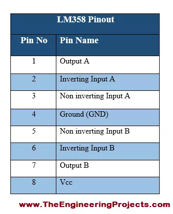
1. LM358 Pinout
LM 358 has eight (8) pins in total having different individual functions associated with each of them.
All the pins along with their sequence number are given in the table shown below.
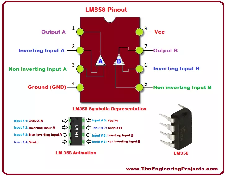
2. LM358 Pins Configuration
A properly labeled pin diagram of any device results in better standing of the user.
I have made a completely labeled diagram of LM-358 diode along with its animation.
The complete pinout diagram along with animation, symbolic representation and the real image of LM 358 is shown in the figure below.
3. LM358 Packages
LM 358 has four (4) different type of packages DSBGA, PDIP, TO-CAN and SOT-23(5).
All of theses packages along with their dimensions and part number are given in the table shown below.
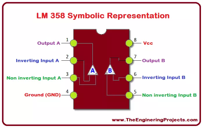
4. LM358 Symbolic Representation
Symbolic for of a device shows its internal circuitry.
LM 358 symbolic representation is shown in the figure below.
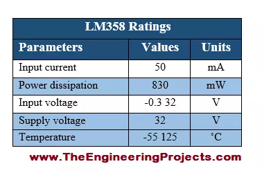
5. LM358 Ratings
The voltage, current and power ratings of any device shows its power requirement i.e. how much amount of current and voltage is sufficient for its operation.
I have provided LM-358 current, power and voltage ratings in the table shown below.
6. LM358 Advantages
LM-358 has several different advantages, a few of which are given below.
There is no need of dual supply.
Compatibility with all forms of logic.
Two Op-amps, compensated internally.
Power drain suitable for battery operation.
Direct sensing near ground.
7. LM358 Applications
LM 358 has a wide range of real life applications, few of the major applications are given below.
DC gain blocks.
General signal conditioning.
Transducer amplifiers.
General signal amplification.
Active filters.
Operational amplifier circuits.
Current loop transmitters for 4 to 20mA.
7. LM358 Proteus Simulation
I have also designed a Proteus Simulation of LM358 which will give you better idea of its working.
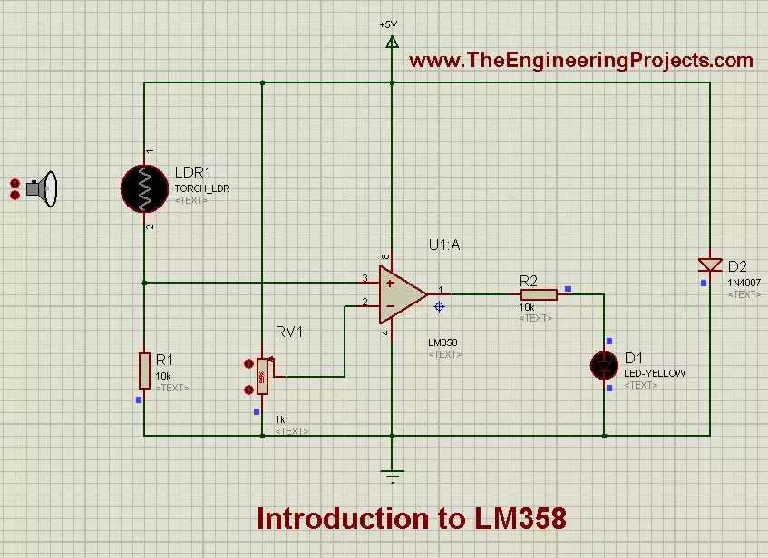
In this simulation, I have designed a small automatic LED ON OFF circuit depending on LDR value.
The image is shown in below figure:
You can see in above figure that I have attached the LDR at input pins while the LED is attached at the output pin of LM358.
Now when LDR is dark, then LED will remain OFF but when LDR will come in Light then LED will also turn ON.
The variable resistor is used for sensitivity purposes.
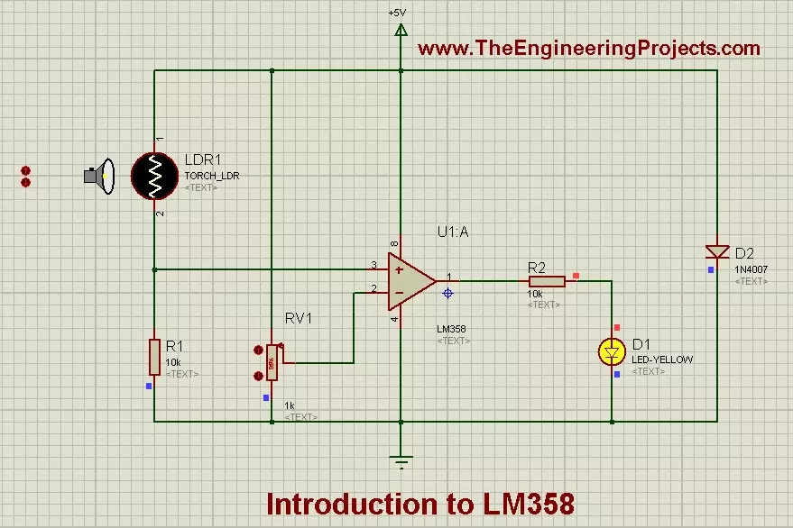
In the below image I have shown its ON state:
You can see in above figure that now LED is ON because LDR is in LIGHT.
You can download this LM358 Proteus Simulation by clicking the below button:
So, that is all from the tutorial Introduction to LM358. I hope you enjoyed this tutorial. If you have any kind of problem, you can ask me in comments, any time you want, without even feeling a bit of hesitation. I will try my level best to sort out your problems in a better way, if possible. Our team is also 24/7 here to help you out. I will explore further IC's and diodes in my upcoming tutorial and will surely share all of them with you as well. So, till then, Take Care :)
syedzainnasir
I am Syed Zain Nasir, the founder of The Engineering Projects (TEP). I am a
programmer since 2009 before that I just search things, make small projects and now I am sharing my
knowledge through this platform. I also work as a freelancer and did many projects related to
programming and electrical circuitry. My Google Profile+Follow
Get Connected
Comments on ‘’ Introduction to LM358 ‘’ ( 2 )
0
davidpilling
Says:
diode is probably reverse supply connection protection
Reply
100
1
necdetaslan
Says:
Hi Mohammet
I am a Turkish professor of physics. I am trying to use LM358 for developing an instrumentation amplifier
for hall effect sensor. I have following questions:
1. is there any protheus device for hall effect sensor
2. In the above circuit you give what is the reason of 1N4007 diode.? Is it not short circuiting power supply?
3. Whatever gain I try to get by adjusting resistors, the output voltage of LMN358 cannot be greater than 3.8 V. What is the reason for that?
Reply