Hello friends, I hope you all are doing great. In today's tutorial, we are gonna have a look at detailed Introduction to DS1307. DS1307 is a real-time clock. It is a low power device and also has battery backup, which provides power when its external power supply not working or is off. It works on the I2C protocol. It is a bidirectional device and it can send and receive data on both sides.
DS1307 is used in industrial projects where constant time and date of some projects or working is required. I will give you a detailed overview of this time and date indicator IC. In today's post, we will have a look at its pinout, working, basic circuit, protocol, etc. I will also share some links of projects where I have interfaced it with Arduino and some other Microcontrollers. Friends, if you have any questions, please ask in comments and I will try my best to solve your problems and will give you comprehensive answers. So let's get started with basic Introduction to DS1307:
Introduction to DS1307
DS1307 is a Real-Time Control (RTC) IC. In DS1307, data is transferred in binary decimal coded, bits pattern. The data transfer rate in DS1307 is 56 bytes.
The memory which is used in DS1307 is NV SRAM. NV SRAM is basically a non-volatile random access memory. In working, NV SRAM is quite similar to static random access memory(SRAM).
DS1307 is an electronic device which plays an impotent role in real-time embedded systems. In embedded systems, we can get benefits of system clocks, students attendance time and date, we can also use it as an alarm for special work.
DS1307 consists of a built-in power-sense circuit. The purpose of the built-in power-sense circuit is that if power gets cut-off, then it will automatically switch to back up power supply. In this way, our circuit remains in working condition.
The protocol on which DS1307 works is I2C. I2C is a single line protocol in which data is transferred bit by bit along a single wire.
Now let's have a look at DS1307 Pinout:
DS1307 Pinout
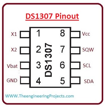
DS1307 has a total of 8 pinouts, which are described below:
PIN 1,2: These pins are for standard 32.768 quartz crystals. Both pins can be used as input and output for internal oscillator. If X1 is input then X2 is used as output.
PIN 3: This pin is used for battery connection to DS1307.
PIN 4: We have to apply Ground on this pin.
PIN 5: This pin is labeled as SDA, which is short for Serial Data Line.
PIN 6: It is used for serial clock input (SCL) and data synchronized.
PIN 7: This pin is used for output square wave obtainer (SQW).
PIN 8: At this pin, we provide an external power supply (Vcc).
Now let's have a look at the pinout picture:
Now let's have a look at I2C protocol
I2C Protocol
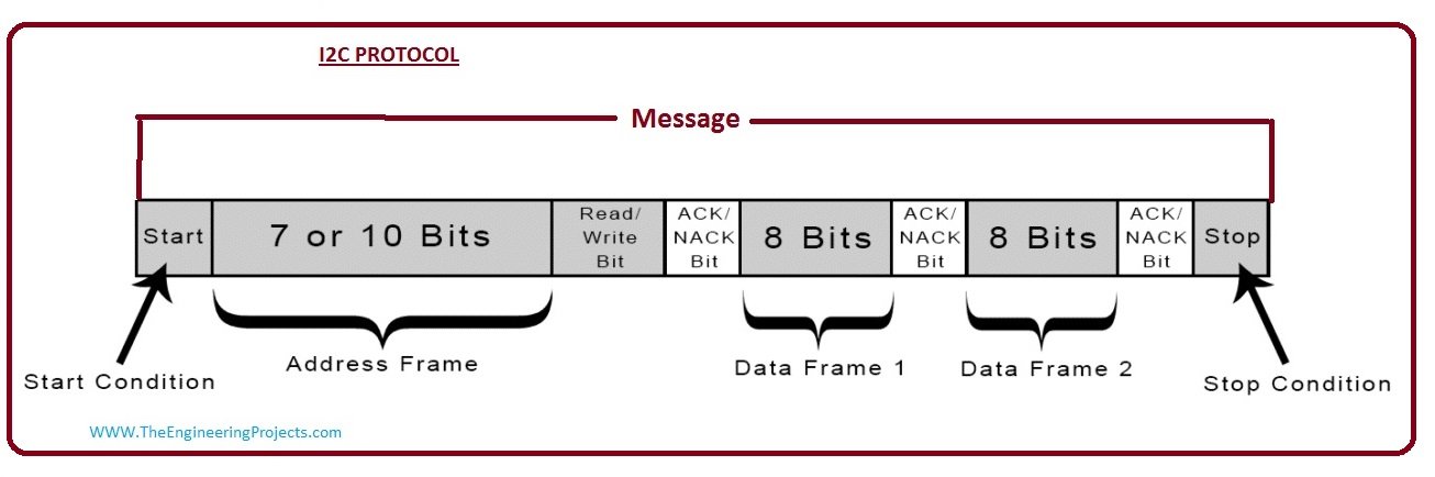
I2C is a serial protocol in which data is transferred bit by bit.
I2C combine the best feature of SPI and UART. By using it with one microcontroller we can control many slave devices.
In I2C data is transferred in the form of messages, then we convert messages into data form. Each message has an address frame that contains a binary address of devices which under control.
I2C protocol is cheaper to implement then SPI protocol. SPI control one slave device while I2C control more than one device.
For better understanding lets have a look at the I2C protocol picture.
Now let's have a look at working of DS1307
Working of DS1307
For a better understanding of the working of DS1307 let's discuss a circuit in which we use it.
In this simple circuit, we connect its first two pins which are X1 and X2 with 32.768 kHz crystal oscillator as the source for the chip.
The third pin is connected with a battery of 3V.
At Vcc, we give 5v supply and it can be given by using a microcontroller. If Vcc is not provided then read and write condition are inhibited.
Let us have a look at the circuit:
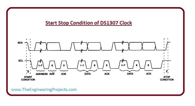
Starts and stop conditions are required when one device wants to communicate with other devices in the I2c protocol.
For obtaining start condition we provide specific identification and address register to a device, by this, we get start condition.
For a better understanding of stop and start condition lets have a look at clock figure.
Let's have a look at Feature of ds1307.
Features of DS1307
In this section, I have designed a table where I have placed all features of DS1307 along with their symbols and units.
No.
Parameter
Symbol
Value
Unit
1.
Supply Voltage
VCC
5
V
2
Logic 1 Input
VIH
2.2
V
3
Logic 0 Input
VIL
+0.8
V
4
VBAT Battery Voltage
VBAT
3.5
V
5
Input Leakage
ILI
1
uA
6
I/O Leakage
ILO
1
uA
7
Logic 0 OUTPUT
VOL
0.4
V
8
Active Supply Current
(fSCL = 100kHz)
ICC
1.5
mA
9
Standby Current
ICCS
200
uA
10
VBAT Leakage Current
IBATLKG
50
nA
11
Power-Fail Voltage (VBAT = 3.0V)
VPFtd>
1.284 x
VBAT
V
12
VBAT Current (OSC ON);
SQW/OUT OFF
IBAT1
500
nA
13
VBAT Current (OSC ON);
SQW/OUT ON (32kHz)
IBAT2
100
nA
14
VBAT Data-Retention Current
(Oscillator Of)
IBATDR
100
nA
15
SCL Clock Frequency
fSCL
100
kHZ
16
Bus Free Time Between a STOP and
START Condition
tBUF
4.7
us
17
Hold Time (Repeated) START
Condition
tHD:STA
4
us
18
LOW Period of SCL Clock
tLOW
4.7
us
19
HIGH Period of SCL Clock
tHIGH
4
us
20
Setup Time for a Repeated START
Condition
tSU:STA
4.7
us
21
Data Hold Time
tHD:DAT
0
us
22
Rise Time of Both SDA and SCL
Signals
tR
1000
ns
23
Fall Time of Both SDA and SCL
Signals
tF
300
ns
24
Setup Time for STOP Condition
tSU:STO
4.7
us
Now, let's discuss applications of DS1307
Applications of DS1307
These are some applications of DS1307, Lets disuses them.
As we know DS1307 is used to tell continues time and date showing purpose, that way it is an electronic device such as a computer, mobile, and laptops.
By using it with Arduino we can use it in several projects related to data logging, alarm, clocks, etc.
So, that was all about this Real Time Clock DS1307. I hope you have enjoyed today's tutorial and it will help you with your engineering projects. Will meet you guys in the next tutorial, till then take care and have fun !!! :)