


Introduction to MPR121


Introduction to MPR121
- MPR121 is a touch sensor controller, its working is like the capacitor's working principle. This module has twelve electrodes points, it communicates via I2C protocol.
- This module has the capability to drive LEDs and GPIO on 4 to 11 electrodes pins, this feature provides freedom to set-up different projects.
- This sensor consumes very low current, it draws only around 29uA current after 16 milliseconds.
- Instead of traditional buttons, this board has four holes which used as an input system.
- The level changer of 3.3v to 5v is surfaced on this chip which provides the facility of 3.3v and 5v I2C interfacing with other microcontrollers.
- On the back side of this module, there are four jumpers which are closed to each other by default.
- The jumper of address pin connects the Add pin to a ground of chip, which indicates that default I2C address of this chip is 0x5A.
- If you want to change the address of the MPR121 chip, first of all, you should open the jumper. Jumpers are also connected with SCL, SDA and interrupt pin.
- The VERG pinout of this module is connected with a ground by a 0.1uF capacitor, which indicates that you can not operate the MPR12 at low supply voltage mode (1.71-2.75VDC) until you modify the board.
- The dimensions of this module are 3cm x 2cm.

MPR121 Pinout & Description
There are main twenty pinouts of MPR121 which are described below.| Pin# | Type | Parameters |
| Pin#1 | IRQ | It is Open Collector Interrupt Output Pin, active low. |
| Pin#2 | SCL | It is I2C Clock pinout. |
| Pin#3 | SDA | It is I2C Data pin. |
| Pin#4 | ADDR | It is I2C Address Select Input Pin. Connect the ADDR pin to the VSS, VDD, SDA or SCL line, the resulting I2C addresses are 0x5A, 0x5B, 0x5C and 0x5D respectively. |
| Pin#5 | VREG | It is Internal Regulator Node. Connect a 0.1 µF bypass cap to VSS. |
| Pin#6 | VSS | Ground. |
| Pin#7 | REXT | It is an External Resistor. Connect a 75 kO 1% resistor to VSS to set internal reference current. |
| Pin#8 | ELE0 | It is Electrode 0 pinout. |
| Pin#9 | ELE1 | It is Electrode 1 pinout |
| Pin#10 | ELE2 | It is Electrode 2 pinout. |
| Pin#11 | ELE3 | It is Electrode 3 pinout. |
| Pin#12 | ELE4 | It is Electrode 4 pinout. |
| Pin#13 | ELE5 | It is Electrode 5 pinout. |
| Pin#14 | ELE6 | It is Electrode 6 pinout. |
| Pin#15 | ELE7 | It is Electrode 7 pinout. |
| Pin#16 | ELE8 | It is Electrode 8 pinout. |
| Pin#17 | ELE9 | It is Electrode 9 pinout. |
| Pin#18 | ELE10 | It is Electrode 10 pinout. |
| Pin#19 | ELE11 | It is Electrode 11 pinout. |
| Pin#20 | Vdd | Connect a 0.1 µF bypass cap to VSS. |

Features of MPR121
- These are some features of MPR121 which are described below.
- Its operating voltage is 1.71V to 3.6V
- Its operating current is 29uA at 16ms sampling interval.
- Its scan stop mode current is 3uA.
- There are twelve electrodes sensing inputs on this module in which 8 are multifunctional for LED driving and GPIO.
- For electrode inputs, it has integrated auto calibration.
- It can configure charge current and charge time for each electrode.
- It's every electrode has separate touch and release trip thresholds, which provides hysteresis and release trip thresholds for each electrode.
- It has an I2C interface, which has IRQ interrupt output to informs electrodes for condition changes.
- The dimensions of 3 mm x 3 mm x 0.65 mm 20 with the lead QFN package.
- It's operating temperature is range is -40°C to +85° C.
MPR121 Capacitance Measurement & Touching Sensing
- The capacitance measurement part of MPR121 is consists of a sensing electrode pad which is connected with the sensing inputs of MPR121. MPR121 used the I2C bus and interrupt output for communication with the processor of a host device.
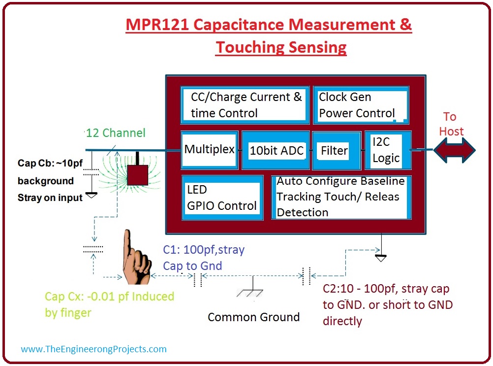
- There are 13 sensing channels, in which 12 channels have physical inputs electrodes and one multiplexer, and the 13th channel is used for proximity detection.
- From a given diagram, we can see that multiplexer is fixed at the front end, due to this all thirteen channel can be measured in sequence within time. After capacitance measurement, this sensor gets filtered noise by which we can observe touch or release button status.
- Except for the measurement of touch sensing, MPR121 is also used in industries for capacitive measurement applications.
- You can send up to ten-bit data ( which indicates a high level of the noise elimination) for capacitance measurement outputs like measurement of water level, displacement measurement, and change of medium content measurement.
- The measurement of capacitance on each channel is the capacitance to the ground which is the sum of background parasitic capacitance to ground (Cb) and a finger touched induced capacitance (Cx).
- The ground is in common ground when the module is not in an active state when the device is connected with batteries this ground is referred to MPR121 ground.
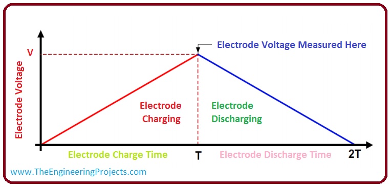
- MPR121 used DC current for measurement of capacitance. For measurement of capacitance every channel first charged and then discharged to ground, this process you can see in a given diagram.
- We can read values of all channels one by one when one channel is charged or discharged, other channels are connected to ground.
- A quantity of charge can be varied by changing the value of current and charge. After charging of electrode, the value of peak voltage can be measured by 10-bit ADC. These output voltages are inversely proportional to the value of capacitance on all the channels.


Applications MPR121
- These are some applications of MPR121.
- It is used in PC Peripherals.
- It is used in MP3 Players.
- It is used in Remote Controls.
- It used in Mobile Phones.
- It is used for Lighting Controls.
×
![]()


