


Introduction to RN4020


Introduction to RN4020
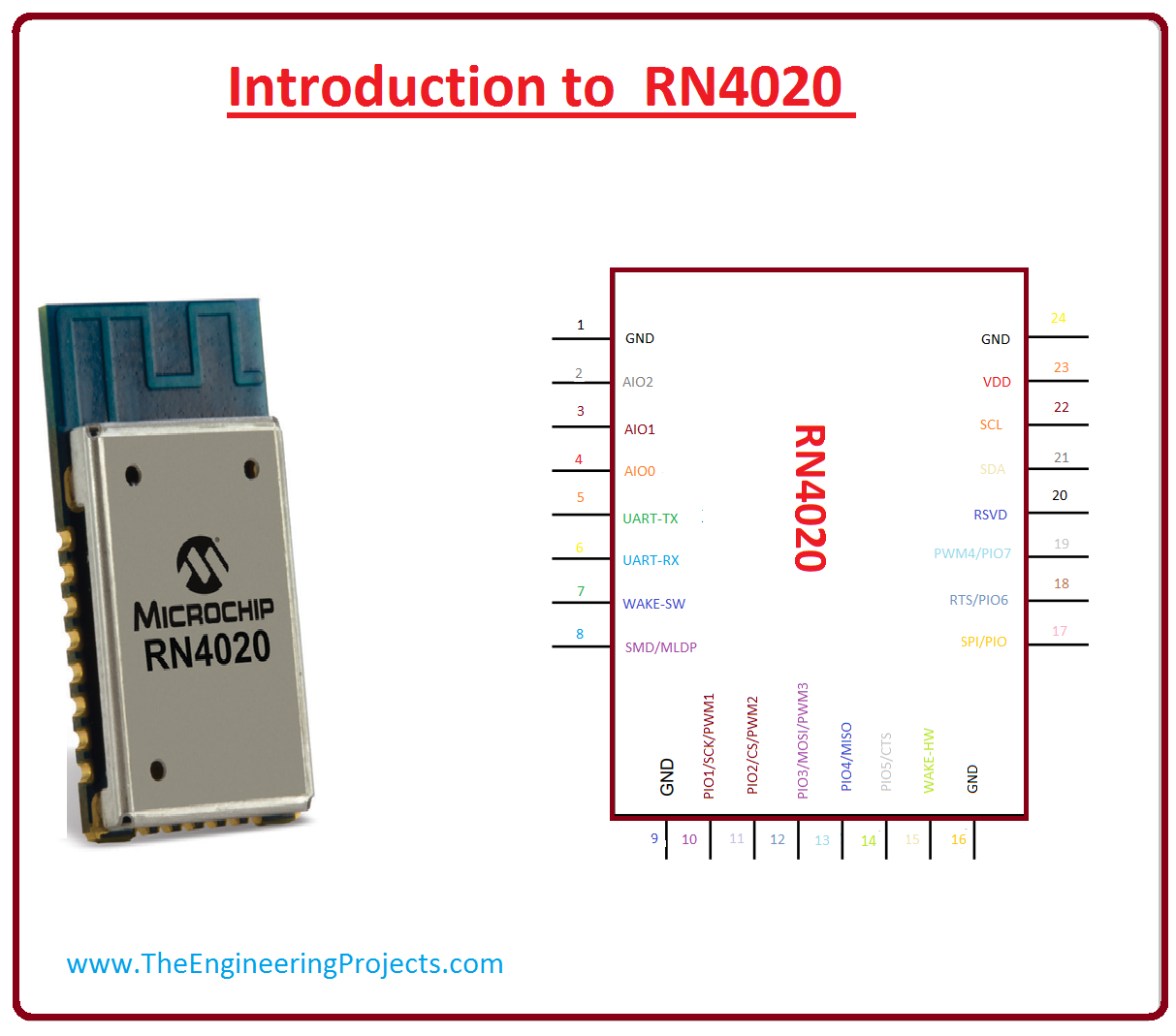
- RN4020 is a completely licensed Bluetooth category 4.1 low energy consuming unit. This module is surfaced with the Bluetooth which is organized by Unpretentious ASCII instructions by UART interfacing.
- This unit incorporates RF, a base-band regulator, and an API (application program interface) processor, which makes it a low energy user Bluetooth module.
- It has an inherent high-performance PCB antenna which is modified for elongated assortment, normally over 100 meters distance.
- Its compressed dimensions allow the comfort of incorporation in size- controlled applications. It is used in any less expensive microcontroller for intellectual Bluetooth low energy consuming applications.
- For unpretentious sensor use, its interior scripting abilities allow straightforward functions to be applied without the need for exterior host Microcontrollers or software development tools.
- It provisions 13 communal sketches and 18 communal amenities, which are implemented by Bluetooth Special Interest Group (SIG). For all sustained contours and facilities, RN4020 could be organized to act as waitperson and customer roles at the equivalent period.
- Besides, RN4020 provisions Microchip sequestered contour Microchip Low Power Data Profile (MLDP) that put on Serial Port Profile (SPP), which is well-defined in Bluetooth Definitive and allows data tributary between two expedients.
Pinout of RN4020
- These are the main pinout of RN4020 which are described below.
Pin# Type Parameters Pin#1 GND It is ground pinout. Pin#2 AIO2 It is analog programmable bi directional input output pinout. Pin#3 AIO1 It is analog programmable bi directional input output pinout. Pin#4 AIO0 It is analog programmable bi directional input output pinout. Pin#5 UART TX It is a UART Transmitter (TX) pinout. Pin#6 UART RX It is a UART Receiver (RX) pin. Pin#7 WAKE_SW It is bottomless Snooze Awaken when it becomes active it rouse module from Unfathomable Snooze. Pin#8 CMD/MLDP It works in command and MLDP mode, in command mode, UART data send to the command translator. During the MLDP method, UART data is sent to MLDP Bluetooth UART LED contacts. Pin#9 GND It is a ground pin. Pin#10 CONNECTION LED PIO[1] SCK PWM1 It is an evasion condition output. When it is in the energetic condition it shows that the device is linked with the distant expedient. When it is not energetic it displays there is no association with another expedient. Pin#11 MLDP_EV PIO[2] CS PWM2 It is for MLDP data indication. If it is in the high state which means that data has acknowledged, in a low state, there is no data. Pin#12 WS PIO[3] MOSI PWM3 It is output for movement indication. If it in energetic state component is working properly if not the device is not working. Pin#13 PIO[4] MISO It is MISO for Diagnostics and Workshop Regulation if a pin 17 avowed. Pin#14 CTS PIO[5] It is earmarked for CTS if hardware movement controller is permitted on the UART. Pin#15 WAKE_HW It is hardware wakeup from the latent condition. Set the Pin (15) high state to module eliminates from the inactive condition. Pin#16 GND It is a ground pin. Pin#17 SPI/PIO SPI/PIO for pinouts 10-13, active. Pin#18 RTS PIO[6] It Earmarked for RTS if hardware movement controller on UART is empowered. If the data communication to RN4020 requisite is stopped, declare RTS to high. RTS pin functions self-sufficiently from the CTS (pin 14). Pin#19 PWM4 PIO[7] It is a standby PIO. Pin#20 RSVD It is DMOS comprehensive Bridge 2 Yield A pin Pin#21 SDA It is SDA Statistics contour of the I2C interfacing. The RN4020 constantly performances as the I2C Dominant. Pin#22 SCL It is I2C Clock. Pin#23 VDD It is a power supply. Pin#24 GND It is ground pinout. 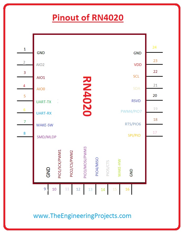

Features of RN4020
- These are some features of RN4020.
- It is entirely specialized Bluetooth form 4.1 component.
- It is on-panel Bluetooth Squat Energy 4.1 heap.
- On this module, ASCII expertise interfaced API over UART.
- This module has DFU above UART or Above the air.
- For sequential transmission of data, it has MLDP.
- This module sends and receive data to distant areas and can control them.
- It hs 64 KB interior flash memory.
- The dimensions of this module are 11.5 x 19.5 x 2.5 mm.
- This module has SMT wads for tranquil and unswerving PCB escalating.
- It is naturally sociable, RoHS amenable.
- It is certified by FCC, IC, CE, QDID.
RN4020 Power Modes
-
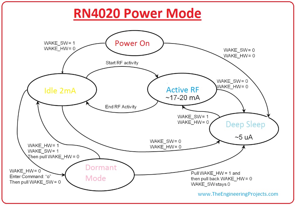
The RN4020 can function in a diversity of power conditions, dependent upon the solicitation required.
- These are the main four power modes of RN4020.
Active RF:
This power state comes in upon any compulsory RF action (TX/RX) through publicity, detection, coupling, assembly, etc.
Deep Sleep:
This is the less-power modes reinforced by the RN4020. The main topographies of this state-run is that publicizing packages are still airing. To place the RN4020 in Deep Sleep method after Idle state you should follow some rules.- Put the WAKW-HW pin in low condition.
- Wrench the WAKE-SW pin in zero condition.
Dormant:
It is the last power mode which reinforced by the RN4020. To place the RN4020 in this mode you should follow some rules.- WAKE-HW pin should be in a low state.
- After this put o command.
- Then instantaneously wrench the WAKE_SW pin to low state.

Applications of RN4020
- These are some applications of RN4020.
- It is used in medical equipment such as Glucose measurement meter, heart pulse measurement.
- It used to check aptness of different sports such as cycling computing.
- It used to tag and stalking of assets.
- It used for Immediacy publicity.
- It used to control distant devices.
- It is used for entrenched Expedient governor.
- It is used for AV comforts and game supervisors.
- It used in handheld Smart devices and Equipment
- It used in home automation.
×
![]()


